EP1562007B1 - Dispositif de raccordement - Google Patents
Dispositif de raccordement Download PDFInfo
- Publication number
- EP1562007B1 EP1562007B1 EP05450007A EP05450007A EP1562007B1 EP 1562007 B1 EP1562007 B1 EP 1562007B1 EP 05450007 A EP05450007 A EP 05450007A EP 05450007 A EP05450007 A EP 05450007A EP 1562007 B1 EP1562007 B1 EP 1562007B1
- Authority
- EP
- European Patent Office
- Prior art keywords
- connection
- valve
- heating
- stopcock
- connection means
- Prior art date
- Legal status (The legal status is an assumption and is not a legal conclusion. Google has not performed a legal analysis and makes no representation as to the accuracy of the status listed.)
- Expired - Lifetime
Links
- 238000010438 heat treatment Methods 0.000 claims abstract description 108
- 230000001105 regulatory effect Effects 0.000 claims description 9
- 230000000903 blocking effect Effects 0.000 claims description 6
- 238000007789 sealing Methods 0.000 claims description 4
- 238000009434 installation Methods 0.000 claims description 3
- 238000005192 partition Methods 0.000 claims description 3
- 230000000295 complement effect Effects 0.000 claims description 2
- 230000001276 controlling effect Effects 0.000 claims description 2
- 239000012530 fluid Substances 0.000 claims 8
- 238000004891 communication Methods 0.000 description 2
- 230000008439 repair process Effects 0.000 description 2
- 230000008859 change Effects 0.000 description 1
- 238000010276 construction Methods 0.000 description 1
- 230000007547 defect Effects 0.000 description 1
- 230000001419 dependent effect Effects 0.000 description 1
- 238000004519 manufacturing process Methods 0.000 description 1
- 238000000034 method Methods 0.000 description 1
Images




Classifications
-
- F—MECHANICAL ENGINEERING; LIGHTING; HEATING; WEAPONS; BLASTING
- F24—HEATING; RANGES; VENTILATING
- F24D—DOMESTIC- OR SPACE-HEATING SYSTEMS, e.g. CENTRAL HEATING SYSTEMS; DOMESTIC HOT-WATER SUPPLY SYSTEMS; ELEMENTS OR COMPONENTS THEREFOR
- F24D19/00—Details
- F24D19/0002—Means for connecting central heating radiators to circulation pipes
- F24D19/0004—In a one pipe system
-
- F—MECHANICAL ENGINEERING; LIGHTING; HEATING; WEAPONS; BLASTING
- F24—HEATING; RANGES; VENTILATING
- F24D—DOMESTIC- OR SPACE-HEATING SYSTEMS, e.g. CENTRAL HEATING SYSTEMS; DOMESTIC HOT-WATER SUPPLY SYSTEMS; ELEMENTS OR COMPONENTS THEREFOR
- F24D19/00—Details
- F24D19/0002—Means for connecting central heating radiators to circulation pipes
- F24D19/0075—Valves for isolating the radiator from the system
Definitions
- connection fitting according to the preamble of claim 1.
- a connection fitting is eg from document DE-N-9421996 known.
- Connection fittings for connecting a radiator to a heating circuit are known in various designs.
- Connection fittings in particular valves directly connected to the heating circuit, which regulate the flow and return of heating medium to the radiator and back, usually have a fixed predetermined flow path for the flow and a fixed predetermined flow path for the return. This has the disadvantage that you can mount the valve when mounting on the on-site usually already existing nozzle of the heating only pointing in a predetermined direction or would have to cross the nozzle. Otherwise, an advantageous flow through the radiator would not exist.
- valves in which the flow paths for the flow and for the return can be mutually changed or merged so that the valve can be mounted on the nozzles of the heating circuit and only then the flow paths of the valve are set ,
- valves are known with which an adjustment or a change of the flow direction is adjustable during operation.
- valves are known in which a part of the heating medium flowing into the valve flows through a specially designed, separately running channel directly and without detour via the radiator from the supply pipe to the return pipe and thus back into the heating circuit. This ensures that even when the valve position is blocked there is a constant heating medium flow and the heating circuit remains uninterrupted.
- connection fitting of the type mentioned above is characterized in that a structurally simple way of regulating the flow or the flow paths during operation and effective shut-off of the radiator is made possible. According to the invention this is achieved in a connection fitting of the type mentioned by the characterizing features of claim 1.
- the proposed measures make it possible to make the valve very small and compact. In addition, there are advantages through a simplified manufacturing process or by weight and material savings. The control options are also improved.
- the features of claim 4 ensure that the flow paths for the heating medium are easily adjustable in an advantageous manner. As a result, the inflow from the heating medium to the radiator can also be prevented and a repair or replacement of the radiator is possible without affecting the heating circuit.
- valve can be easily mounted on any side of the radiator or the connection can be made to the heating circuit in any radial direction.
- valve or the chick are adjustable or adjustable from both sides.
- a regulating unit is provided which is arranged in an ergonomically correct position.
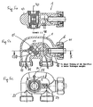
- connection fitting comprises a valve 1 and may optionally, as described below, in addition to the valve 1 include further components.
- the valve 1 is connectable with its two terminals 13, 14 to a, in particular designed as a single-pipe system, heating circuit and connected via a further connection with a T-piece 2.
- the radiator 9 itself has two connections, namely a radiator flow connection 8 and a Radiator return port 7. Between the T-piece 2 and the radiator flow connection 8, in particular on a connecting pipe 4, a regulating unit 3a, 3b is provided, which is either thermostatically regulated or manually regulated.
- the regulating unit 3a, 3b can also be provided directly on the valve 1 or in the region of the T-piece 2.
- the radiator flow connection 8 is located at the upper end of the radiator 9 and the heating medium is via the connecting pipe 4 and the regulating unit 3a, 3b via this radiator flow connection 8 into the radiator 9 fed.
- the cooled heating medium leaves the radiator 9 via the radiator return connection 7 provided at the lower end of the radiator and flows via the T-piece 2 back into the heating circuit via the valve 1.
- connection fitting only consists of or is formed from the valve 1 connected directly to the radiator 9 via corresponding connecting piece.
- the valve 1 has two heating circuit side connections, namely a first port 13 and a second port 14 through which the heating medium from the heating circuit to the valve 1 and subsequently into the radiator 9 and from the radiator 9 via the Valve back into the heating circuit can flow. Which of the two connections 13, 14 is to serve as a supply connection is selectable.
- a substantially cylindrical plug 15 which is rotatably mounted with respect to its central longitudinal or cylindrical axis 40 in a, preferably centrally located, recess or bore of the valve 1.
- the plug 15 controls the flow paths of the heating medium from the heating circuit through the valve 1 to the radiator 9 and back or releases or blocks them.
- the chick 15 is shown in detail.
- the chick 15 has two mutually opposite recesses or recesses 400 of the cylindrical basic shape. Due to these recesses 400, which need not extend over the entire height range of the plug 15, a partition wall 30 is formed by the remaining cylinder body.
- the plug 15 has two diametrically opposite, in particular circular, sealing surfaces 42 on, takes place at the predetermined positions of the plug 15 relative to the flow paths, in particular in a locking position 0 described in more detail below, a shutoff of the flow paths or in the housing partitions of the valve 1 formed flow openings.
- two diametrically opposed, in particular convexly curved, guide surfaces 43 are formed by the recesses 400, through which the flow paths are formed or defined or limited and deflected.
- At least one bypass opening 17 is provided, which in particular has a cylindrical basic shape, and whose central axis 50 extends substantially perpendicular to the central longitudinal axis 40 of the valve 1.
- an open bypass connection 35 is provided, which connects the first connection 13 to the second connection 14 in a fluid-conducting or flow-related manner, almost independently of the position or position of the plug 15.
- the size of the bypass opening 17 will be described later.
- the valve 1 has in its with respect to the terminals 13 and 14 averted area provided for the heating flow 20 output channel 19, can flow through the heating medium through a, in particular laterally provided on the valve, outlet from the valve 1 to the radiator 9 out.
- the valve 1 has a, in particular tubular, provided for the heating return 18 input channel 16, through the heating medium from the radiator 9 in the valve 1, in one, in particular helical or spindle-shaped wound, connecting channel 48, is fed.
- This connection channel 48 adjoining the plug 15 has a fluid-conducting connection to the second connection 14 and can be regarded as a partial region of the second connection 14. From there, the heating medium returns to the heating circuit.
- the two channels 16 and 19 are in the embodiment according to the invention advantageously constructively designed so that the input channel 16 is at least partially in the output channel 19 and is at least partially enclosed by this.
- Such a design is particularly space-saving. It is advantageous if the output channel and the input channel 16 have a common central axis 45.
- a first flow position (I) by a rotation of the plug 15 is reached from the zero or locking position (0), starting in the clockwise direction, the chick 15 is in the present embodiment so that the following flow paths are permitted:
- the heating medium passes through the acting as a supply port first port 13 on the chick 15th
- the heating return 18 passes through the input channel 16 back into the valve 1 and leaves via the plug 15 and the connecting channel 48 via the second port 14, the valve 1 and flows back into the heating circuit.
- a constant Rothfluidstrom flows through the bypass connection 35, from the first port 13 through the bypass port 17 via the second port 14 back to the heating circuit.
- the bypass opening 17 is dimensioned such that in the first flow position I and in the second flow position II 40 to 70%, in particular 45 to 60%, preferably about 50%, of the heating medium flowing into the valve 1 through one of the ports 13 or 14 through the Bypass opening 17 flows back into the heating circuit without entering the radiator 9.
- optimal distribution of the heat stored in the heating medium is ensured on the radiator of the heating circuit and the heating circuit itself.
- the dimensioning of the bypass opening 17 is dependent on the size of the radiator, the number of connected to the heating circuit radiator and other factors and can be interpreted accordingly, knowing these parameters, i. Different chicks 15 with correspondingly large bypass openings 17 can be inserted into the radiators 9.
- the dimensions of the bypass openings 17 in the individual radiators 9 of a single heating circuit can differ in such a way that For example, for the first radiator of a monotube heating circuit, a chick 15 is selected with a larger bypass opening 17 than for the last or the more rear connected radiator 9 of the heating circuit, in which a smaller bypass opening 17 may be necessary to this radiator 9 still enough to be able to supply thermal energy.
- the heating medium should always leave the valve 1 through the outlet channel 19 as a heating flow 20 in the direction of radiator 9 and should always flow back as a heating return 18 from the radiator 9 via the inlet channel 16 into the valve 1.
- This ensures that the heating medium always flows into the same connection of the heating element 9, namely advantageously the radiator feed connection 8, independently of the direction of flow in the heating circuit.
- the inflow into the radiator 9 could be reversed, but this is unfavorable for heating considerations, since the heating power of the radiator is reduced.
- the flow direction in the first port 13 or in the second port 14 changes depending on the position of the plug 15. This ensures that the valve 1 can be placed on the on-site usually preassembled nozzle, regardless of the predetermined in the heating circuit flow direction of the heating medium. That is, the valves 1 can be mounted without knowledge or consideration of the flow direction without having to cross over pipes.
- the plug 15 In the blocking position (0), the plug 15 is positioned so that the sealing surfaces 40 obstruct the entrance to the outlet channel 19 and the connection between the inlet channel 16 and the connections 13 and 14. That is, the fluidic connection of the first terminal 13 and the second terminal 14 with the output channel 19 and with the input channel 16 is no longer given.
- indicia in the form of arrows 23, 24 are provided, which indicate the direction of the flow and after which the position of the plug 15 can be made.
- connection fitting further comprises in the embodiment according to the invention a T-piece 2, which is fluidically connected to the outlet channel 19 and the inlet channel 16 of the valve 1.
- This T-piece 2 ensures that the heat flow from the valve 1 spatially separated from the heating return 18 20 is passed to the radiator flow connection 8 of the radiator and that the heating return 18 passes separately into the inlet channel 16 of the valve 1.
- a tubular element 12 is provided in the T-piece 2, which in particular has the same diameter as the input channel 16 and is in direct flow communication therewith or, in particular tight, connected or connectable to this.
- This tubular element 12 can advantageously be designed such that it projects at least partially through the radiator return connection 7 of the heating element 9 into the heating element 9.
- Fig. 7a and 7b The tube element 12, the inlet channel 16 and the outlet channel 19 have a common central axis 45. This ensures that the valve 1 relative to or relative to the rigidly arranged in this embodiment T-piece 2 about this central axis 45 is rotatable or pivotable. This is important during installation or during assembly, since it is unimportant by this structural design, whether the valve 1 and the T-piece 2 are located to the left or right of the radiator 9.
- the pivoting of the valve 1 relative to the T-piece 2 and the radiator 9 is also advantageous for the reason that thereby the connection to the heating circuit perpendicular to the axis 45 in any radial directions or angular position, preferably down into the ground or after behind the wall or at an angle, can take place or a connection to projecting from the wall on-site connections can easily be made.
- the chick 15 and / or the T-piece 2 are substantially symmetrical with respect to a center plane 55 of the valve 1 perpendicular to the central longitudinal or cylindrical axis 40 of the chick.
- the chick 15 is accessible from both sides of the center plane 55 and can also be switched or adjusted from both sides. This ensures maximum connection variability.
Landscapes
- Engineering & Computer Science (AREA)
- Physics & Mathematics (AREA)
- Thermal Sciences (AREA)
- Chemical & Material Sciences (AREA)
- Combustion & Propulsion (AREA)
- Mechanical Engineering (AREA)
- General Engineering & Computer Science (AREA)
- Steam Or Hot-Water Central Heating Systems (AREA)
- Mechanical Coupling Of Light Guides (AREA)
- Joining Of Corner Units Of Frames Or Wings (AREA)
Claims (10)
- Dispositif de raccordement pour raccorder au moins un corps de chauffe (9) à une circulation de chauffage, particulièrement formée comme système à tube unique, d'une installation de chauffage, comprenant une ou consistant d'une soupape (1) de commande ou de réglage, connectée à la circulation de chauffage avec un conduit d'alimentation et un conduit de reflux, les chemins de passage du milieu de chauffage à partir de la circulation de chauffage à travers la soupape (1) vers le corps de chauffe (9) et retour étant réglés par une noix de robinet (15) sensiblement cylindrique, mobile autour son axe longitudinal ou de cylindre (40), qui ferme ou ouvre mutuellement les chemins de passage en fonction de sa position, dans lequel une dérivation (35) est donnée entre les raccords de la soupape (1) au côté de la circulation de chauffage et prévus pour le conduit d'alimentation ou le conduit de reflux à partir de ou dans la circulation de chauffage, à savoir un premier raccord (13) et un deuxième raccord (14), ladite dérivation (35) passant à travers la noix de robinet (15), caractérisé en ce, que l'axe de rotation ou longitudinal ou de cylindre (40) de la noix de robinet (15) est perpendiculaire au ce plan, qui est étendu par les axes moyens du premier raccord (13) et du deuxième raccord (14).
- Dispositif de raccordement selon la revendication 1, caractérisé en ce, qu'au moins une ouverture de dérivation (17) définie, particulièrement cylindrique, est formé dans la noix de robinet (15), particulièrement dans une cloison de séparation (30) formé par des creux (400) pratiqués dans la noix de robinet (15), dont l'axe central (50) s'étend d'une manière avantageuse sensiblement perpendiculairement à l'axe longitudinal ou de cylindre (40) de la noix de robinet (15), la dérivation passant à travers l'ouverture de dérivation (17).
- Dispositif de raccordement selon la revendication 1 ou 2, caractérisé en ce, que la soupape (1) comprend un canal de sortie (19) au côté du corps de chauffe, à travers lequel le milieu de chauffage passe de la circulation de chauffage au corps de chauffe (9), et un canal d'entrée (16) au côté du corps de chauffe, à travers lequel le milieu de chauffage passe du corps de chauffage (9) retour à la circulation de chauffage, le canal d'entrée (16) étant, au moins partiellement, dans le canal de sortie (19) ou est entouré, au moins partiellement, par celui-ci, et que le canal de sortie (19) et le canal d'entrée (16) comprennent, le cas échéant, un axe central (45) en commun.
- Dispositif de raccordement selon la revendication 2 ou 3, caractérisé en ce, que- la noix de robinet (15) dans la soupape (1) a au moins une position de passage (I), dans laquelle le premier raccord (13), ayant la fonction d'un raccord d'alimentation, est relié d'une façon conduisant le fluide et se rapportant à la technique des fluides au canal de sortie (19), tandis que le deuxième raccord (14), ayant la fonction d'un raccord de reflux, est relié d'une façon conduisant le fluide et se rapportant à la technique des fluides au canal d'entrée (16), le premier raccord (13) étant relié d'une façon conduisant le fluide et se rapportant à la technique des fluides directement au deuxième raccord (14) à travers l'ouverture de dérivation (17),- que la noix de robinet (15) dans la soupape (1) a au moins une deuxième position de passage (II) complémentaire, dans laquelle le deuxième raccord (14), ayant la fonction d'un raccord d'alimentation, est relié d'une façon conduisant le fluide et se rapportant à la technique des fluides au canal de sortie (19), tandis que le premier raccord (13), ayant la fonction d'un raccord de reflux, est relié d'une façon conduisant le fluide et se rapportant à la technique des fluides au canal d'entrée (16), le premier raccord (13) étant relié d'une façon conduisant le fluide et se rapportant à la technique des fluides directement au deuxième raccord (14) à travers l'ouverture de la dérivation (17),- et que la noix de robinet (15) dans la soupape (1) a au moins une position de fermeture (0), dans laquelle les connexions d'une façon conduisant le fluide et se rapportant à la technique des fluides du premier raccord (13) et du deuxième raccord (14) au canal de sortie (19) ainsi qu'au canal d'entrée (16) sont fermées, et c'est seulement le premier raccord (13), qui est relié au deuxième raccord (14) d'une façon conduisant le fluide et se rapportant à la technique des fluides à travers l'ouverture de dérivation (17).
- Dispositif de raccordement selon la revendication 4, caractérisé en ce, que la noix de robinet (15) comprend deux surfaces d'étanchéité (42) diamétralement opposées, par lesquelles une fermeture des chemins de passage est effectuée, particulièrement dans la position de fermeture (0), et que la noix de robinet (15) comprend deux surfaces guideuses (43) diamétralement opposées, étant en particulier envoûté en forme convexe, qui se joignent aux surfaces d'étanchéité (42), étant en particulier circulaires, et par lesquelles les chemins de passage sont formés et définis ou limités, particulièrement dans la première position de passage (I) et dans la deuxième position de passage (II).
- Dispositif de raccordement selon la revendication 4, caractérisé en ce, que l'ouverture de dérivation (17) est dimensionnée de sorte, que dans la première position de passage (I) et dans la deuxième position de passage (II) 40 à 70%, particulièrement 45 à 60%, de préférence environ 50%, du milieu coulant dans la soupape (1) passe par l'ouverture de dérivation (17).
- Dispositif de raccordement selon une quelconque des revendications 3 à 6, caractérisé en ce, qu'un pièce en T (2) relié au canal de sortie (19) et au canal d'entrée (16) de la soupape (1), par lequel le milieu de chauffage peut, séparé du reflux du corps de chauffe (9), être convoyé comme alimentation dans le corps de chauffe (9), dont un bout est relié à un raccord d'alimentation de radiateur (8) du corps de chauffe (9), tandis que l'autre bout est relié à un raccord de reflux de radiateur (7) du corps de chauffe (9), particulièrement à travers un élément de tube (12) prévu dans la pièce en T (2), qui est en connexion directe de courant avec le canal d'entrée (16) de la soupape (1) ou peut être connecté avec ceci, et dont au moins une partie partielle se dresse de préférence dans le corps de chauffe (9), préférablement dans la zone du raccord de reflux de radiateur (7).
- Dispositif de raccordement selon la revendication 7, caractérisé en ce, que l'élément de tube (12), le canal d'entrée (16) et le canal de sortie (19) ont un axe central (45) en commun, et que la soupape (1) peut être tournée ou pivotée autour de cet axe (45) relativement à la pièce en T (2), pour garantir le raccord de la soupape (1) à la circulation de chauffage dans une position angulaire quelconque.
- Dispositif de raccordement selon la revendication 7 ou 8, caractérisé en ce, que la noix de robinet (15) et/ou la pièce en T (2) sont sensiblement symétriques par rapport à un plan moyen (55) de la soupape (1), qui s'étend perpendiculairement é l'axe central longitudinal ou de cylindre (40) de la noix de robinet (15), ou que la noix de robinet (15) est accessible et peut être mis au point ou ajustée des deux côtés du plan moyen (55) ou de l'extérieur d'un boîtier (47) et/ou que, particulièrement entre la pièce en T (2) et le raccord d'alimentation de radiateur (8), une unité de régulation (3a, 3b), en particulier réglée manuellement ou d'une façon thermostatique, est prévue pour la commande ou le réglage du rendement calorifique.
- Dispositif de raccordement selon une quelconque des revendications 2 à 9, caractérisé en ce, que l'axe de rotation de la noix de robinet (15) se trouve entre les axes longitudinaux de premier raccord (13) et du deuxième raccord (14) et/ou que l'ouverture de dérivation (17) est formée au centre de la noix de robinet (15).
Applications Claiming Priority (2)
| Application Number | Priority Date | Filing Date | Title |
|---|---|---|---|
| AT862004 | 2004-01-23 | ||
| AT0008604A AT500154B1 (de) | 2004-01-23 | 2004-01-23 | Anschlussarmatur |
Publications (3)
| Publication Number | Publication Date |
|---|---|
| EP1562007A2 EP1562007A2 (fr) | 2005-08-10 |
| EP1562007A3 EP1562007A3 (fr) | 2005-11-16 |
| EP1562007B1 true EP1562007B1 (fr) | 2008-03-12 |
Family
ID=34658433
Family Applications (1)
| Application Number | Title | Priority Date | Filing Date |
|---|---|---|---|
| EP05450007A Expired - Lifetime EP1562007B1 (fr) | 2004-01-23 | 2005-01-24 | Dispositif de raccordement |
Country Status (3)
| Country | Link |
|---|---|
| EP (1) | EP1562007B1 (fr) |
| AT (2) | AT500154B1 (fr) |
| DE (1) | DE502005003154D1 (fr) |
Families Citing this family (1)
| Publication number | Priority date | Publication date | Assignee | Title |
|---|---|---|---|---|
| WO2010004350A2 (fr) * | 2008-07-11 | 2010-01-14 | John Terence Crilly | Radiateur à moyens de commande |
Family Cites Families (8)
| Publication number | Priority date | Publication date | Assignee | Title |
|---|---|---|---|---|
| US2229931A (en) * | 1938-07-22 | 1941-01-28 | Arthur L Parker | Valve |
| CH518473A (it) * | 1969-12-19 | 1972-01-31 | Reato Vincenzo | Rubinetto d'otturazione di un radiatore in impianti di riscaldamento con alimentazione monotubo in serie |
| DD106687A1 (fr) * | 1973-07-20 | 1974-06-20 | ||
| DE2540435A1 (de) * | 1975-09-11 | 1977-03-17 | Ulrich Dipl Ing Graf | Vierwegmischventil fuer heizkoerper und heizkessel |
| EP0130075A3 (fr) * | 1983-06-28 | 1985-02-06 | Polyventions S.A. | Appareil de chauffage et ensemble de valves pour un tel appareil |
| DE9421935U1 (de) * | 1993-05-10 | 1997-03-20 | Kermi Gmbh, 94447 Plattling | Anschlußvorrichtung zum Anschluß eines Heizkörpers und Patrone zum Einbau in diese |
| DE19539046C1 (de) * | 1995-10-20 | 1996-12-05 | Centra Buerkle Gmbh & Co | Mischventil |
| DE19607694A1 (de) * | 1996-02-29 | 1997-09-04 | Theodor Nocon | Anschlußblock für Vor- und Rücklauf mit Flußrichtungsumkehrelement (Gebäudeheizungsanlage) |
-
2004
- 2004-01-23 AT AT0008604A patent/AT500154B1/de not_active IP Right Cessation
-
2005
- 2005-01-24 DE DE502005003154T patent/DE502005003154D1/de not_active Expired - Fee Related
- 2005-01-24 AT AT05450007T patent/ATE389154T1/de not_active IP Right Cessation
- 2005-01-24 EP EP05450007A patent/EP1562007B1/fr not_active Expired - Lifetime
Also Published As
| Publication number | Publication date |
|---|---|
| EP1562007A3 (fr) | 2005-11-16 |
| AT500154B1 (de) | 2006-12-15 |
| EP1562007A2 (fr) | 2005-08-10 |
| DE502005003154D1 (de) | 2008-04-24 |
| ATE389154T1 (de) | 2008-03-15 |
| AT500154A1 (de) | 2005-11-15 |
Similar Documents
| Publication | Publication Date | Title |
|---|---|---|
| DE60019481T2 (de) | Klappeanordnung und Fluidumlauf- und Verteilergerät mit einer solchen Anordnung | |
| DE102019128897A1 (de) | Mehrwegeventil, Fluidkreislauf und Kühlfluidkreislauf | |
| DE3614425A1 (de) | Elektromagnetische mehrfunktions-absperrorgananordnung | |
| DE3826778C2 (fr) | ||
| DE102008036778A1 (de) | Schaltsystem zum Umgehen eines EGR-Kühlers | |
| DE19834575C5 (de) | Drehschieberventil | |
| DE60001482T2 (de) | Heizungs- und klimaanlage mit einer luftmischklappe | |
| DE69924647T2 (de) | Plattenwärmetauscher mit integriertem ventil | |
| DE102010006038B4 (de) | Vorrichtung zur Regelung eines Fluidstroms | |
| EP1747354B1 (fr) | Echangeur de chaleur, en particulier pour refroidisseurs de gaz d'echappement de moteurs a combustion interne | |
| EP1562007B1 (fr) | Dispositif de raccordement | |
| DE112016005186B4 (de) | Thermostatkartusche zum Regeln von zu mischenden warmen und kalten Fluiden | |
| EP1607694B1 (fr) | Dispositif de raccordement | |
| DE102011084297A1 (de) | Anschlusskörper für einen Heizkörper | |
| DE3422336C2 (fr) | ||
| EP3012553B1 (fr) | Composant pour une installation de chauffage | |
| EP0700501B1 (fr) | Raccord pour le raccordement a leur source de chaleur de radiateurs faisant partie du circuit de chauffage de l'installation de chauffage d'un batiment | |
| EP1801474A1 (fr) | Vanne à boisseau sphérique à voies multiples | |
| EP2093516B1 (fr) | Composant pour installation de chauffage compacte | |
| EP2136153B1 (fr) | Radiateur plat | |
| DE102005021395A1 (de) | Wärmetauscher, insbesondere für Abgaskühler von Brennkraftmaschinen | |
| DE102012019069A1 (de) | Bypasseinheit für ein Einstrangheizungs- oder -kühlsystem | |
| DE112022003326T5 (de) | Thermostatische Sanitärmischbatterie, sowie modulare thermostatische Sanitärmischbatterieeinheit | |
| EP2282137B1 (fr) | Unité d'échangeur thermique comprenant des éléments de direction de flux d'air | |
| DE102017205150B4 (de) | Fluidregler und Anordnung mit einem solchen Fluidregler und einer Pumpe |
Legal Events
| Date | Code | Title | Description |
|---|---|---|---|
| PUAI | Public reference made under article 153(3) epc to a published international application that has entered the european phase |
Free format text: ORIGINAL CODE: 0009012 |
|
| AK | Designated contracting states |
Kind code of ref document: A2 Designated state(s): AT BE BG CH CY CZ DE DK EE ES FI FR GB GR HU IE IS IT LI LT LU MC NL PL PT RO SE SI SK TR |
|
| AX | Request for extension of the european patent |
Extension state: AL BA HR LV MK YU |
|
| PUAL | Search report despatched |
Free format text: ORIGINAL CODE: 0009013 |
|
| AK | Designated contracting states |
Kind code of ref document: A3 Designated state(s): AT BE BG CH CY CZ DE DK EE ES FI FR GB GR HU IE IS IT LI LT LU MC NL PL PT RO SE SI SK TR |
|
| AX | Request for extension of the european patent |
Extension state: AL BA HR LV MK YU |
|
| 17P | Request for examination filed |
Effective date: 20060415 |
|
| AKX | Designation fees paid |
Designated state(s): AT BE BG CH CY CZ DE DK EE ES FI FR GB GR HU IE IS IT LI LT LU MC NL PL PT RO SE SI SK TR |
|
| AXX | Extension fees paid |
Extension state: MK Payment date: 20060415 Extension state: BA Payment date: 20060415 Extension state: HR Payment date: 20060415 Extension state: LV Payment date: 20060415 Extension state: YU Payment date: 20060415 Extension state: AL Payment date: 20060415 |
|
| GRAP | Despatch of communication of intention to grant a patent |
Free format text: ORIGINAL CODE: EPIDOSNIGR1 |
|
| GRAS | Grant fee paid |
Free format text: ORIGINAL CODE: EPIDOSNIGR3 |
|
| GRAA | (expected) grant |
Free format text: ORIGINAL CODE: 0009210 |
|
| AK | Designated contracting states |
Kind code of ref document: B1 Designated state(s): AT BE BG CH CY CZ DE DK EE ES FI FR GB GR HU IE IS IT LI LT LU MC NL PL PT RO SE SI SK TR |
|
| AX | Request for extension of the european patent |
Extension state: AL BA HR LV MK YU |
|
| REG | Reference to a national code |
Ref country code: GB Ref legal event code: FG4D Free format text: NOT ENGLISH |
|
| REG | Reference to a national code |
Ref country code: CH Ref legal event code: EP |
|
| REG | Reference to a national code |
Ref country code: IE Ref legal event code: FG4D Free format text: LANGUAGE OF EP DOCUMENT: GERMAN |
|
| REF | Corresponds to: |
Ref document number: 502005003154 Country of ref document: DE Date of ref document: 20080424 Kind code of ref document: P |
|
| REG | Reference to a national code |
Ref country code: GR Ref legal event code: EP Ref document number: 20080401344 Country of ref document: GR |
|
| PG25 | Lapsed in a contracting state [announced via postgrant information from national office to epo] |
Ref country code: FI Free format text: LAPSE BECAUSE OF FAILURE TO SUBMIT A TRANSLATION OF THE DESCRIPTION OR TO PAY THE FEE WITHIN THE PRESCRIBED TIME-LIMIT Effective date: 20080312 Ref country code: LT Free format text: LAPSE BECAUSE OF FAILURE TO SUBMIT A TRANSLATION OF THE DESCRIPTION OR TO PAY THE FEE WITHIN THE PRESCRIBED TIME-LIMIT Effective date: 20080312 |
|
| NLV1 | Nl: lapsed or annulled due to failure to fulfill the requirements of art. 29p and 29m of the patents act | ||
| PG25 | Lapsed in a contracting state [announced via postgrant information from national office to epo] |
Ref country code: PL Free format text: LAPSE BECAUSE OF FAILURE TO SUBMIT A TRANSLATION OF THE DESCRIPTION OR TO PAY THE FEE WITHIN THE PRESCRIBED TIME-LIMIT Effective date: 20080312 Ref country code: SI Free format text: LAPSE BECAUSE OF FAILURE TO SUBMIT A TRANSLATION OF THE DESCRIPTION OR TO PAY THE FEE WITHIN THE PRESCRIBED TIME-LIMIT Effective date: 20080312 |
|
| REG | Reference to a national code |
Ref country code: IE Ref legal event code: FD4D |
|
| PG25 | Lapsed in a contracting state [announced via postgrant information from national office to epo] |
Ref country code: SE Free format text: LAPSE BECAUSE OF FAILURE TO SUBMIT A TRANSLATION OF THE DESCRIPTION OR TO PAY THE FEE WITHIN THE PRESCRIBED TIME-LIMIT Effective date: 20080612 Ref country code: PT Free format text: LAPSE BECAUSE OF FAILURE TO SUBMIT A TRANSLATION OF THE DESCRIPTION OR TO PAY THE FEE WITHIN THE PRESCRIBED TIME-LIMIT Effective date: 20080818 Ref country code: CZ Free format text: LAPSE BECAUSE OF FAILURE TO SUBMIT A TRANSLATION OF THE DESCRIPTION OR TO PAY THE FEE WITHIN THE PRESCRIBED TIME-LIMIT Effective date: 20080312 Ref country code: ES Free format text: LAPSE BECAUSE OF FAILURE TO SUBMIT A TRANSLATION OF THE DESCRIPTION OR TO PAY THE FEE WITHIN THE PRESCRIBED TIME-LIMIT Effective date: 20080623 Ref country code: SK Free format text: LAPSE BECAUSE OF FAILURE TO SUBMIT A TRANSLATION OF THE DESCRIPTION OR TO PAY THE FEE WITHIN THE PRESCRIBED TIME-LIMIT Effective date: 20080312 |
|
| PG25 | Lapsed in a contracting state [announced via postgrant information from national office to epo] |
Ref country code: NL Free format text: LAPSE BECAUSE OF FAILURE TO SUBMIT A TRANSLATION OF THE DESCRIPTION OR TO PAY THE FEE WITHIN THE PRESCRIBED TIME-LIMIT Effective date: 20080312 Ref country code: RO Free format text: LAPSE BECAUSE OF FAILURE TO SUBMIT A TRANSLATION OF THE DESCRIPTION OR TO PAY THE FEE WITHIN THE PRESCRIBED TIME-LIMIT Effective date: 20080312 |
|
| PG25 | Lapsed in a contracting state [announced via postgrant information from national office to epo] |
Ref country code: IS Free format text: LAPSE BECAUSE OF FAILURE TO SUBMIT A TRANSLATION OF THE DESCRIPTION OR TO PAY THE FEE WITHIN THE PRESCRIBED TIME-LIMIT Effective date: 20080712 |
|
| EN | Fr: translation not filed | ||
| PLBE | No opposition filed within time limit |
Free format text: ORIGINAL CODE: 0009261 |
|
| STAA | Information on the status of an ep patent application or granted ep patent |
Free format text: STATUS: NO OPPOSITION FILED WITHIN TIME LIMIT |
|
| PG25 | Lapsed in a contracting state [announced via postgrant information from national office to epo] |
Ref country code: IE Free format text: LAPSE BECAUSE OF FAILURE TO SUBMIT A TRANSLATION OF THE DESCRIPTION OR TO PAY THE FEE WITHIN THE PRESCRIBED TIME-LIMIT Effective date: 20080312 Ref country code: DK Free format text: LAPSE BECAUSE OF FAILURE TO SUBMIT A TRANSLATION OF THE DESCRIPTION OR TO PAY THE FEE WITHIN THE PRESCRIBED TIME-LIMIT Effective date: 20080312 |
|
| 26N | No opposition filed |
Effective date: 20081215 |
|
| PG25 | Lapsed in a contracting state [announced via postgrant information from national office to epo] |
Ref country code: FR Free format text: LAPSE BECAUSE OF FAILURE TO SUBMIT A TRANSLATION OF THE DESCRIPTION OR TO PAY THE FEE WITHIN THE PRESCRIBED TIME-LIMIT Effective date: 20090102 Ref country code: EE Free format text: LAPSE BECAUSE OF FAILURE TO SUBMIT A TRANSLATION OF THE DESCRIPTION OR TO PAY THE FEE WITHIN THE PRESCRIBED TIME-LIMIT Effective date: 20080312 Ref country code: BG Free format text: LAPSE BECAUSE OF FAILURE TO SUBMIT A TRANSLATION OF THE DESCRIPTION OR TO PAY THE FEE WITHIN THE PRESCRIBED TIME-LIMIT Effective date: 20080612 |
|
| PG25 | Lapsed in a contracting state [announced via postgrant information from national office to epo] |
Ref country code: MC Free format text: LAPSE BECAUSE OF NON-PAYMENT OF DUE FEES Effective date: 20090131 |
|
| REG | Reference to a national code |
Ref country code: CH Ref legal event code: PL |
|
| GBPC | Gb: european patent ceased through non-payment of renewal fee |
Effective date: 20090124 |
|
| PG25 | Lapsed in a contracting state [announced via postgrant information from national office to epo] |
Ref country code: CY Free format text: LAPSE BECAUSE OF FAILURE TO SUBMIT A TRANSLATION OF THE DESCRIPTION OR TO PAY THE FEE WITHIN THE PRESCRIBED TIME-LIMIT Effective date: 20080312 |
|
| PG25 | Lapsed in a contracting state [announced via postgrant information from national office to epo] |
Ref country code: LI Free format text: LAPSE BECAUSE OF NON-PAYMENT OF DUE FEES Effective date: 20090131 Ref country code: CH Free format text: LAPSE BECAUSE OF NON-PAYMENT OF DUE FEES Effective date: 20090131 Ref country code: DE Free format text: LAPSE BECAUSE OF NON-PAYMENT OF DUE FEES Effective date: 20090801 |
|
| PG25 | Lapsed in a contracting state [announced via postgrant information from national office to epo] |
Ref country code: GB Free format text: LAPSE BECAUSE OF NON-PAYMENT OF DUE FEES Effective date: 20090124 |
|
| PG25 | Lapsed in a contracting state [announced via postgrant information from national office to epo] |
Ref country code: BE Free format text: LAPSE BECAUSE OF NON-PAYMENT OF DUE FEES Effective date: 20090131 |
|
| PG25 | Lapsed in a contracting state [announced via postgrant information from national office to epo] |
Ref country code: AT Free format text: LAPSE BECAUSE OF NON-PAYMENT OF DUE FEES Effective date: 20090124 |
|
| PG25 | Lapsed in a contracting state [announced via postgrant information from national office to epo] |
Ref country code: LU Free format text: LAPSE BECAUSE OF NON-PAYMENT OF DUE FEES Effective date: 20090124 |
|
| PG25 | Lapsed in a contracting state [announced via postgrant information from national office to epo] |
Ref country code: HU Free format text: LAPSE BECAUSE OF FAILURE TO SUBMIT A TRANSLATION OF THE DESCRIPTION OR TO PAY THE FEE WITHIN THE PRESCRIBED TIME-LIMIT Effective date: 20080913 |
|
| PG25 | Lapsed in a contracting state [announced via postgrant information from national office to epo] |
Ref country code: TR Free format text: LAPSE BECAUSE OF FAILURE TO SUBMIT A TRANSLATION OF THE DESCRIPTION OR TO PAY THE FEE WITHIN THE PRESCRIBED TIME-LIMIT Effective date: 20080312 |
|
| PGFP | Annual fee paid to national office [announced via postgrant information from national office to epo] |
Ref country code: GR Payment date: 20170116 Year of fee payment: 13 |
|
| PGFP | Annual fee paid to national office [announced via postgrant information from national office to epo] |
Ref country code: IT Payment date: 20170124 Year of fee payment: 13 |
|
| PG25 | Lapsed in a contracting state [announced via postgrant information from national office to epo] |
Ref country code: GR Free format text: LAPSE BECAUSE OF NON-PAYMENT OF DUE FEES Effective date: 20180802 |
|
| PG25 | Lapsed in a contracting state [announced via postgrant information from national office to epo] |
Ref country code: IT Free format text: LAPSE BECAUSE OF NON-PAYMENT OF DUE FEES Effective date: 20180124 |