EP1562012A1 - Kühlsystem - Google Patents
Kühlsystem Download PDFInfo
- Publication number
- EP1562012A1 EP1562012A1 EP05002353A EP05002353A EP1562012A1 EP 1562012 A1 EP1562012 A1 EP 1562012A1 EP 05002353 A EP05002353 A EP 05002353A EP 05002353 A EP05002353 A EP 05002353A EP 1562012 A1 EP1562012 A1 EP 1562012A1
- Authority
- EP
- European Patent Office
- Prior art keywords
- gas cooler
- refrigerant
- heat
- heat insulating
- compressor
- Prior art date
- Legal status (The legal status is an assumption and is not a legal conclusion. Google has not performed a legal analysis and makes no representation as to the accuracy of the status listed.)
- Granted
Links
- 239000003507 refrigerant Substances 0.000 title claims abstract description 226
- 238000005057 refrigeration Methods 0.000 claims abstract description 60
- 239000011810 insulating material Substances 0.000 claims abstract description 6
- 238000009413 insulation Methods 0.000 claims abstract description 5
- CURLTUGMZLYLDI-UHFFFAOYSA-N Carbon dioxide Chemical compound O=C=O CURLTUGMZLYLDI-UHFFFAOYSA-N 0.000 claims description 26
- 229910002092 carbon dioxide Inorganic materials 0.000 claims description 14
- 239000001569 carbon dioxide Substances 0.000 claims description 14
- 230000005494 condensation Effects 0.000 abstract description 6
- 238000009833 condensation Methods 0.000 abstract description 6
- 239000007789 gas Substances 0.000 description 146
- 238000001816 cooling Methods 0.000 description 30
- 230000000694 effects Effects 0.000 description 10
- 239000000203 mixture Substances 0.000 description 6
- QGZKDVFQNNGYKY-UHFFFAOYSA-N Ammonia Chemical compound N QGZKDVFQNNGYKY-UHFFFAOYSA-N 0.000 description 5
- 230000006835 compression Effects 0.000 description 5
- 238000007906 compression Methods 0.000 description 5
- 238000010521 absorption reaction Methods 0.000 description 4
- 238000010586 diagram Methods 0.000 description 4
- 239000007788 liquid Substances 0.000 description 4
- 239000010687 lubricating oil Substances 0.000 description 4
- 238000000034 method Methods 0.000 description 4
- 239000004215 Carbon black (E152) Substances 0.000 description 3
- NBVXSUQYWXRMNV-UHFFFAOYSA-N fluoromethane Chemical compound FC NBVXSUQYWXRMNV-UHFFFAOYSA-N 0.000 description 3
- 229930195733 hydrocarbon Natural products 0.000 description 3
- 150000002430 hydrocarbons Chemical class 0.000 description 3
- 238000004519 manufacturing process Methods 0.000 description 3
- 239000003921 oil Substances 0.000 description 3
- 230000002411 adverse Effects 0.000 description 2
- 229910021529 ammonia Inorganic materials 0.000 description 2
- QVGXLLKOCUKJST-UHFFFAOYSA-N atomic oxygen Chemical compound [O] QVGXLLKOCUKJST-UHFFFAOYSA-N 0.000 description 2
- 230000003247 decreasing effect Effects 0.000 description 2
- 238000010438 heat treatment Methods 0.000 description 2
- 229910052760 oxygen Inorganic materials 0.000 description 2
- 239000001301 oxygen Substances 0.000 description 2
- XLYOFNOQVPJJNP-UHFFFAOYSA-N water Substances O XLYOFNOQVPJJNP-UHFFFAOYSA-N 0.000 description 2
- CBENFWSGALASAD-UHFFFAOYSA-N Ozone Chemical compound [O-][O+]=O CBENFWSGALASAD-UHFFFAOYSA-N 0.000 description 1
- 229910000069 nitrogen hydride Inorganic materials 0.000 description 1
- 229920002635 polyurethane Polymers 0.000 description 1
- 239000004814 polyurethane Substances 0.000 description 1
- 238000010792 warming Methods 0.000 description 1
Images


Classifications
-
- F—MECHANICAL ENGINEERING; LIGHTING; HEATING; WEAPONS; BLASTING
- F25—REFRIGERATION OR COOLING; COMBINED HEATING AND REFRIGERATION SYSTEMS; HEAT PUMP SYSTEMS; MANUFACTURE OR STORAGE OF ICE; LIQUEFACTION SOLIDIFICATION OF GASES
- F25D—REFRIGERATORS; COLD ROOMS; ICE-BOXES; COOLING OR FREEZING APPARATUS NOT OTHERWISE PROVIDED FOR
- F25D19/00—Arrangement or mounting of refrigeration units with respect to devices or objects to be refrigerated, e.g. infrared detectors
- F25D19/02—Arrangement or mounting of refrigeration units with respect to devices or objects to be refrigerated, e.g. infrared detectors plug-in type
-
- F—MECHANICAL ENGINEERING; LIGHTING; HEATING; WEAPONS; BLASTING
- F25—REFRIGERATION OR COOLING; COMBINED HEATING AND REFRIGERATION SYSTEMS; HEAT PUMP SYSTEMS; MANUFACTURE OR STORAGE OF ICE; LIQUEFACTION SOLIDIFICATION OF GASES
- F25B—REFRIGERATION MACHINES, PLANTS OR SYSTEMS; COMBINED HEATING AND REFRIGERATION SYSTEMS; HEAT PUMP SYSTEMS
- F25B9/00—Compression machines, plants or systems, in which the refrigerant is air or other gas of low boiling point
- F25B9/002—Compression machines, plants or systems, in which the refrigerant is air or other gas of low boiling point characterised by the refrigerant
- F25B9/008—Compression machines, plants or systems, in which the refrigerant is air or other gas of low boiling point characterised by the refrigerant the refrigerant being carbon dioxide
-
- F—MECHANICAL ENGINEERING; LIGHTING; HEATING; WEAPONS; BLASTING
- F25—REFRIGERATION OR COOLING; COMBINED HEATING AND REFRIGERATION SYSTEMS; HEAT PUMP SYSTEMS; MANUFACTURE OR STORAGE OF ICE; LIQUEFACTION SOLIDIFICATION OF GASES
- F25D—REFRIGERATORS; COLD ROOMS; ICE-BOXES; COOLING OR FREEZING APPARATUS NOT OTHERWISE PROVIDED FOR
- F25D23/00—General constructional features
- F25D23/003—General constructional features for cooling refrigerating machinery
-
- F—MECHANICAL ENGINEERING; LIGHTING; HEATING; WEAPONS; BLASTING
- F25—REFRIGERATION OR COOLING; COMBINED HEATING AND REFRIGERATION SYSTEMS; HEAT PUMP SYSTEMS; MANUFACTURE OR STORAGE OF ICE; LIQUEFACTION SOLIDIFICATION OF GASES
- F25D—REFRIGERATORS; COLD ROOMS; ICE-BOXES; COOLING OR FREEZING APPARATUS NOT OTHERWISE PROVIDED FOR
- F25D23/00—General constructional features
- F25D23/06—Walls
- F25D23/061—Walls with conduit means
-
- F—MECHANICAL ENGINEERING; LIGHTING; HEATING; WEAPONS; BLASTING
- F25—REFRIGERATION OR COOLING; COMBINED HEATING AND REFRIGERATION SYSTEMS; HEAT PUMP SYSTEMS; MANUFACTURE OR STORAGE OF ICE; LIQUEFACTION SOLIDIFICATION OF GASES
- F25B—REFRIGERATION MACHINES, PLANTS OR SYSTEMS; COMBINED HEATING AND REFRIGERATION SYSTEMS; HEAT PUMP SYSTEMS
- F25B1/00—Compression machines, plants or systems with non-reversible cycle
- F25B1/04—Compression machines, plants or systems with non-reversible cycle with compressor of rotary type
-
- F—MECHANICAL ENGINEERING; LIGHTING; HEATING; WEAPONS; BLASTING
- F25—REFRIGERATION OR COOLING; COMBINED HEATING AND REFRIGERATION SYSTEMS; HEAT PUMP SYSTEMS; MANUFACTURE OR STORAGE OF ICE; LIQUEFACTION SOLIDIFICATION OF GASES
- F25B—REFRIGERATION MACHINES, PLANTS OR SYSTEMS; COMBINED HEATING AND REFRIGERATION SYSTEMS; HEAT PUMP SYSTEMS
- F25B1/00—Compression machines, plants or systems with non-reversible cycle
- F25B1/10—Compression machines, plants or systems with non-reversible cycle with multi-stage compression
-
- F—MECHANICAL ENGINEERING; LIGHTING; HEATING; WEAPONS; BLASTING
- F25—REFRIGERATION OR COOLING; COMBINED HEATING AND REFRIGERATION SYSTEMS; HEAT PUMP SYSTEMS; MANUFACTURE OR STORAGE OF ICE; LIQUEFACTION SOLIDIFICATION OF GASES
- F25B—REFRIGERATION MACHINES, PLANTS OR SYSTEMS; COMBINED HEATING AND REFRIGERATION SYSTEMS; HEAT PUMP SYSTEMS
- F25B2309/00—Gas cycle refrigeration machines
- F25B2309/06—Compression machines, plants or systems characterised by the refrigerant being carbon dioxide
- F25B2309/061—Compression machines, plants or systems characterised by the refrigerant being carbon dioxide with cycle highest pressure above the supercritical pressure
-
- F—MECHANICAL ENGINEERING; LIGHTING; HEATING; WEAPONS; BLASTING
- F25—REFRIGERATION OR COOLING; COMBINED HEATING AND REFRIGERATION SYSTEMS; HEAT PUMP SYSTEMS; MANUFACTURE OR STORAGE OF ICE; LIQUEFACTION SOLIDIFICATION OF GASES
- F25B—REFRIGERATION MACHINES, PLANTS OR SYSTEMS; COMBINED HEATING AND REFRIGERATION SYSTEMS; HEAT PUMP SYSTEMS
- F25B40/00—Subcoolers, desuperheaters or superheaters
-
- F—MECHANICAL ENGINEERING; LIGHTING; HEATING; WEAPONS; BLASTING
- F25—REFRIGERATION OR COOLING; COMBINED HEATING AND REFRIGERATION SYSTEMS; HEAT PUMP SYSTEMS; MANUFACTURE OR STORAGE OF ICE; LIQUEFACTION SOLIDIFICATION OF GASES
- F25D—REFRIGERATORS; COLD ROOMS; ICE-BOXES; COOLING OR FREEZING APPARATUS NOT OTHERWISE PROVIDED FOR
- F25D2317/00—Details or arrangements for circulating cooling fluids; Details or arrangements for circulating gas, e.g. air, within refrigerated spaces, not provided for in other groups of this subclass
- F25D2317/06—Details or arrangements for circulating cooling fluids; Details or arrangements for circulating gas, e.g. air, within refrigerated spaces, not provided for in other groups of this subclass with forced air circulation
- F25D2317/065—Details or arrangements for circulating cooling fluids; Details or arrangements for circulating gas, e.g. air, within refrigerated spaces, not provided for in other groups of this subclass with forced air circulation characterised by the air return
- F25D2317/0651—Details or arrangements for circulating cooling fluids; Details or arrangements for circulating gas, e.g. air, within refrigerated spaces, not provided for in other groups of this subclass with forced air circulation characterised by the air return through the bottom
-
- F—MECHANICAL ENGINEERING; LIGHTING; HEATING; WEAPONS; BLASTING
- F25—REFRIGERATION OR COOLING; COMBINED HEATING AND REFRIGERATION SYSTEMS; HEAT PUMP SYSTEMS; MANUFACTURE OR STORAGE OF ICE; LIQUEFACTION SOLIDIFICATION OF GASES
- F25D—REFRIGERATORS; COLD ROOMS; ICE-BOXES; COOLING OR FREEZING APPARATUS NOT OTHERWISE PROVIDED FOR
- F25D2317/00—Details or arrangements for circulating cooling fluids; Details or arrangements for circulating gas, e.g. air, within refrigerated spaces, not provided for in other groups of this subclass
- F25D2317/06—Details or arrangements for circulating cooling fluids; Details or arrangements for circulating gas, e.g. air, within refrigerated spaces, not provided for in other groups of this subclass with forced air circulation
- F25D2317/066—Details or arrangements for circulating cooling fluids; Details or arrangements for circulating gas, e.g. air, within refrigerated spaces, not provided for in other groups of this subclass with forced air circulation characterised by the air supply
- F25D2317/0661—Details or arrangements for circulating cooling fluids; Details or arrangements for circulating gas, e.g. air, within refrigerated spaces, not provided for in other groups of this subclass with forced air circulation characterised by the air supply from the bottom
-
- F—MECHANICAL ENGINEERING; LIGHTING; HEATING; WEAPONS; BLASTING
- F25—REFRIGERATION OR COOLING; COMBINED HEATING AND REFRIGERATION SYSTEMS; HEAT PUMP SYSTEMS; MANUFACTURE OR STORAGE OF ICE; LIQUEFACTION SOLIDIFICATION OF GASES
- F25D—REFRIGERATORS; COLD ROOMS; ICE-BOXES; COOLING OR FREEZING APPARATUS NOT OTHERWISE PROVIDED FOR
- F25D2317/00—Details or arrangements for circulating cooling fluids; Details or arrangements for circulating gas, e.g. air, within refrigerated spaces, not provided for in other groups of this subclass
- F25D2317/06—Details or arrangements for circulating cooling fluids; Details or arrangements for circulating gas, e.g. air, within refrigerated spaces, not provided for in other groups of this subclass with forced air circulation
- F25D2317/068—Details or arrangements for circulating cooling fluids; Details or arrangements for circulating gas, e.g. air, within refrigerated spaces, not provided for in other groups of this subclass with forced air circulation characterised by the fans
- F25D2317/0684—Details or arrangements for circulating cooling fluids; Details or arrangements for circulating gas, e.g. air, within refrigerated spaces, not provided for in other groups of this subclass with forced air circulation characterised by the fans the fans allowing rotation in reverse direction
-
- F—MECHANICAL ENGINEERING; LIGHTING; HEATING; WEAPONS; BLASTING
- F25—REFRIGERATION OR COOLING; COMBINED HEATING AND REFRIGERATION SYSTEMS; HEAT PUMP SYSTEMS; MANUFACTURE OR STORAGE OF ICE; LIQUEFACTION SOLIDIFICATION OF GASES
- F25D—REFRIGERATORS; COLD ROOMS; ICE-BOXES; COOLING OR FREEZING APPARATUS NOT OTHERWISE PROVIDED FOR
- F25D2323/00—General constructional features not provided for in other groups of this subclass
- F25D2323/002—Details for cooling refrigerating machinery
- F25D2323/0026—Details for cooling refrigerating machinery characterised by the incoming air flow
- F25D2323/00264—Details for cooling refrigerating machinery characterised by the incoming air flow through the front bottom part
-
- F—MECHANICAL ENGINEERING; LIGHTING; HEATING; WEAPONS; BLASTING
- F25—REFRIGERATION OR COOLING; COMBINED HEATING AND REFRIGERATION SYSTEMS; HEAT PUMP SYSTEMS; MANUFACTURE OR STORAGE OF ICE; LIQUEFACTION SOLIDIFICATION OF GASES
- F25D—REFRIGERATORS; COLD ROOMS; ICE-BOXES; COOLING OR FREEZING APPARATUS NOT OTHERWISE PROVIDED FOR
- F25D2323/00—General constructional features not provided for in other groups of this subclass
- F25D2323/002—Details for cooling refrigerating machinery
- F25D2323/0027—Details for cooling refrigerating machinery characterised by the out-flowing air
- F25D2323/00271—Details for cooling refrigerating machinery characterised by the out-flowing air from the back bottom
Definitions
- FIG. 8 is an explanatory cross-sectional view of one example of a conventional refrigerant system.
- the conventional refrigerant system 1 A (an example of a showcase) comprises a heat insulating housing 3 provided with an accommodating space 2 inside, and a refrigeration unit 9 attached to a lower portion of the heat insulating housing 3, and in which a compressor 5, a gas cooler 6, a restriction means not shown are disposed on a unit base 4, and an evaporator 8 is accommodated in a heat insulating case 7 attached onto the unit base 4, and the compressor 5, the gas cooler 6, the restriction means not shown, and the evaporator 8 are sequentially connected to form a refrigeration circuit (see for example, Japanese Patent Laid-Open Publication No. H10-96532, No.
- the reference numeral 17 denotes a fan for the gas cooler 6
- the reference numeral 18 denotes a fan for the evaporator 8
- the reference numeral 19 denotes a accommodating shelf for accommodating articles
- the reference numeral 9A denotes an exhaust outlet.
- the heat-dissipated refrigerant passes through an internal heat exchanger not shown, and the refrigerant gas is heat-lost by a low-pressure side refrigerant to be further cooled. Then the cooled high-pressure side refrigerant gas reaches an expansion valve (restriction means) and the pressure is controlled to lower pressure so that the refrigerant gas has a two-phase mixture of gas/liquid.
- the mixture flows into the evaporator 8 as it is and the refrigerant is evaporated there to exhibit a cooling action by heat absorption from air.
- cooled air is introduced into the accommodating space 2 of the heat insulating housing 3 by the fan 18 as shown in an arrow (or in the opposite direction to the arrow) and is circulated.
- the reference numeral 17 denotes a fan for the gas cooler 6, the reference numeral 18 denotes a fan for the evaporator 8, the reference numeral 9A denotes an exhaust outlet and the reference numeral 19 denotes a accommodating shelf for accommodating articles.
- refrigerant system 1E When the refrigerant system 1E is operated, refrigerant gas compressed and discharged with the compressor 5 flows into the gas cooler 6. Then outside air is introduced by the fan 17 as shown by an arrow (or in the opposite direction to the arrow) and is heat-dissipated by an air-cooling system.
- the heat-dissipated refrigerant passes through an inner side tube of the internal heat exchanger 10 composed of a double pipe and refrigerant gas heat exchanges there with a low pressure side refrigerant, which passes through an outer side tube of the internal heat exchanger 10 to be further cooled by being heat lost. Then the cooled high-pressure side refrigerant gas reaches an expansion valve (restriction means) and the pressure is controlled to lower pressure so that the refrigerant gas has a two-phase mixture of gas/liquid. The mixture flows into the evaporator 8 as it is and the refrigerant is evaporated there to exhibit a cooling action by heat absorption from air.
- cooled air is introduced into the accommodating space 2 of the heat insulating housing 3 by the fan 18 as shown in an arrow (or in the opposite direction to the arrow) and is circulated.
- the refrigerant flows out of the evaporator 8 and passes through the outer side tube of the internal heat exchanger 10 to take heat from the high-pressure side refrigerant, which passes through the inner side tube of the internal heat exchanger 10 while receiving the heating action.
- the obtained refrigerant is perfectly gasified and the gasified refrigerant repeats cycles to be sucked into the compressor 5.
- exhaust heat-exchanged by the gas cooler 6 moves in the direction of the internal heat exchanger 10, and after running against the heat insulating case 7 and the internal heat exchanger 10, the exhaust moves around the heat insulating case 7 and internal heat exchanger 10 to flow toward the rear of the heat insulating case 7 and internal heat exchanger 10 so that it is discharged from the exhaust outlet 9A provided on a rear portion of the refrigeration unit 9 to the outside.
- airflow of the exhaust heat-exchanged by the gas cooler 6 is blocked by the heat insulating case 7 and the internal heat exchanger 10, and airflow stagnates around the gas cooler 6 so that heat does not escape.
- the refrigerant pressure reaches about 150 kg/cm 2 G on the high pressure side.
- the refrigerant pressure becomes higher and the refrigerant temperature also becomes higher as compared with fluorocarbon.
- portions, which adjoin between the high pressure side portion and the low pressure side portion are formed in the respective sliding members.
- a refrigerant system comprises a heat insulating housing provided with an accommodating space inside, and a refrigeration unit attached to a lower portion of said heat insulating housing, in which a compressor, a gas cooler, a restriction means and an evaporator accommodated in an insulating case are disposed on a unit base, and a refrigeration circuit is formed by sequentially connecting said compressor, said gas cooler, said restriction means and said evaporator, and the refrigerant system is characterized in that said gas cooler and said insulating case are disposed so that air heat-exchanged by said gas cooler moves toward said heat insulating case, and an air passage is provided between said unit base and said heat insulating case whereby air heat exchanged by said gas cooler is passed through said air passage to be discharged outside.
- a refrigerant system according to fourth aspect of the present invention is characterized in that said refrigeration unit is formed for being detachable and attachable.
- the refrigerant system comprises a heat insulating housing provided with an accommodating space inside, and a refrigeration unit attached to a lower portion of said heat insulating housing, in which a compressor, a gas cooler, a restriction means and an evaporator accommodated in an insulating case are disposed on a unit base, and a refrigeration circuit is formed by sequentially connecting said compressor, said gas cooler, said restriction means and said evaporator, and said gas cooler and said insulating case are disposed so that air heat-exchanged by said gas cooler moves toward said heat insulating case, and an air passage is provided between said unit base and said heat insulating case whereby air heat exchanged by said gas cooler is passed through said air passage to be discharged outside, such remarkable effects that exhaust heat-exchanged by the gas cooler is caused to flow and can be discharged without stagnation of the exhaust, refrigerant gas can be sufficiently cooled in the gas cooler, and that the durability of the compressor can be improved without causing an overload state in the compressor or an increase
- the refrigerant system comprises a heat insulating housing provided with an accommodating space inside, and a refrigeration unit attached to a lower portion of said heat insulating housing, in which a compressor, a gas cooler, an internal heat exchanger, a restriction means and an evaporator accommodated in an insulating case is disposed on a unit base, and a refrigeration circuit is formed by sequentially connecting said compressor, said gas cooler, said internal heat exchanger, said restriction means and said evaporator, and said gas cooler and insulating case are disposed so that air heat exchanged by said gas cooler moves toward said heat insulating case, and an air passage is provided between said unit base and said heat insulating case whereby air heat-exchanged by said gas cooler is passed through said air passage to be discharged outside, and said internal heat exchanger and/or said restriction means are provided in such a manner that they are embedded in a heat insulating material layer provided on an outer periphery of said heat insulating case to be provided with heat insulation,
- the refrigerant system according to third aspect of the present invention is characterized in that at least one exhaust passage is provided at a place of said unit base corresponding to a portion of said air passage, through which most of air heat-exchanged by said gas cooler passes to discharge air heat-exchanged by said gas cooler outside through said exhaust passage, such a more remarkable effect that exhaust is caused to flow well and can be discharged without stagnation is exhibited.
- the refrigerant system according to fourth aspect of the present invention is characterized in that said refrigeration unit is formed removably and the refrigeration unit can be easily attached to or removed from the heat insulating housing, such a more remarkable effect that a refrigeration unit formed in this company is attached to a heat insulating housing formed by another company to assemble and manufacture a refrigerant system of the present invention, or that after a refrigeration unit is removed from the refrigerant system of the present invention and repaired, the refrigeration unit can be attached to the system again to assemble, is exhibited.
- the refrigerant system according to fifth aspect of the present invention is characterized in that carbon dioxide, which exhibits super critical pressure on the high pressure side, is used as a refrigerant and a two-stage compressing rotary compressor is used as said compressor, in a case where carbon dioxide is used as a refrigerant, the refrigerant pressure reaches even about 130 to 150 kg/cm 2 G on the high pressure side and about 30 to 40 kg/cm 2 G on the low pressure side.
- the differential pressure in the respective sliding members becomes about 1/2 and a surface pressure is lowered so that an oil film is ensured, such a more remarkable effect that the generation of a sliding loss or a leak loss can be minimized.
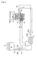
- the reference numeral 5 denotes an internal intermediate pressure type multi-stage (two stage) compressing rotary compressor, and comprises a motor-drive element 14 in a closed vessel 12, and a lower stage rotary compressing element 32 and an upper stage rotary compressing element 34, driven by a rotating shaft 11 of the motor-drive element 14.
- the compressor 5 compresses refrigerant gas sucked through a refrigerant introduction pipe 94 with the lower stage rotary compressing element 32 and discharges it into the closed vessel 12.
- intermediate pressure refrigerant gas in the closed vessel 12 is once discharged to an intermediate cooling circuit 150A through a refrigerant introduction pipe 92.
- the intermediate cooling circuit 150A is provided so that refrigerant gas passes through an intermediate cooling heat exchanger 150B, and then the refrigerant gas is air-cooled and sucked into the upper stage rotary compressing element 34 through the refrigerant introduction pipe 92.
- the refrigerant high pressurized by the second stage compression is discharged through a refrigerant discharge pipe 96 and is air-cooled by a gas cooler 6.
- refrigerant emitted from the gas cooler 6 was heat-exchanged with refrigerant emitted from an evaporator 8 by an internal heat exchanger 10, it passes through a restriction means 16 and enters the evaporator 8. Then after the refrigerant was evaporated, it passes through the internal heat exchanger 10 again and is sucked into the lower stage rotary compressing element 32 through the refrigerant introduction pipe 94.
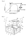
- a refrigerant (a state of 2 in FIG. 3) compressed (while obtaining enthalpy ⁇ h3) by the lower stage rotary compressing element 32 to have intermediate pressure and discharged into the closed vessel 12 emits from the refrigerant pipe 92 and flows into the intermediate cooling circuit 150A. Then, the refrigerant flows into an intermediate cooling heat exchanger 150B through which the intermediate cooling circuit passes, and is heat-dissipated there by an air-cooling system (a state of 3 in FIG. 3). The intermediate pressure refrigerant loses enthalpy ⁇ h1 in the intermediate cooling heat exchanger 150B as shown in FIG. 3.
- the refrigerant is sucked into the upper stage rotary compressing element 34 and the second stage compression is performed to obtain a high-pressure and temperature refrigerant gas, which is discharged to the outside from the refrigerant discharge pipe 96. At this time the refrigerant is compressed up to an appropriate super critical pressure (a state of 4 in FIG. 3).
- the refrigerant gas discharged from the refrigerant discharge pipe 96 flows into the gas cooler 6 and is heat-dissipated there by an air-cooling system (a state of 5' in FIG. 3). After that the refrigerant gas passes through the internal heat exchanger 10. The heat of the refrigerant is taken by a low pressure side refrigerant to be more cooled (a state of 5 in FIG. 3) (enthalpy is lost by ⁇ h2). After that the refrigerant is decompressed by the restriction means 16 while becoming in a gas/liquid mixture state in the process (a state of 6 in FIG. 3), and then flows into the evaporator 8 to be evaporated (a state of 1' in FIG. 3).
- the refrigerant emitted from the evaporator 8 passes through the internal heat exchanger 10 and takes heat from said high-pressure side refrigerant there to be heated (a state of 1 in FIG. 3) (enthalpy is obtained by ⁇ h2). Then the refrigerant is heated by the internal heat exchanger 10 and is perfectly gasified. The gasified refrigerant repeats a cycle where it is sucked into the lower stage rotary compressing element 32 of the rotary compressor 5 from the refrigerant introduction pipe 94.
- the refrigerant evaporated by the evaporator 8 exhibits a cooling action by heat absorption from air, and cooled air is introduced into the accommodating space 2 of the heat insulating housing 3 by the fan 18 as shown by the arrow and is circulated.
- the exhaust heat-exchanged by the gas cooler 6 passes through the air passage T as shown by the arrow and is discharged to the outside from the exhaust outlet 9A.
- FIG. 4 is an explanatory view explaining another refrigerant system according to the present invention.
- a refrigerant system 1B shown in FIG. 4 a skeleton of a refrigeration unit 9 is formed by a combination of U-shaped frame members 21, 22, 23 and 24 as shown in FIG. 4, and fixing members 22A, 23A and 24A for fixing a heat insulating case 7A to predetermined positions of the frame members 22, 23 and 24 are provided.
- fixing members 22B, 23B and 24B are provided at positions of the heat insulating case 7A corresponding to the fixing members 22A, 23A and 24A.
- the fixing members 22B, 23B and 24B of the heat insulating case 7A are made to correspond with the fixing members 22A, 23A and 24A so that the heat insulating case 7A is set on the skeleton of the refrigeration unit 9, and are fixed by screws and the like not shown.
- the refrigerant system 1B is the same as the refrigerant system 1 of the present invention shown in FIG. 1 except that the air passage T was formed between the unit base 4 and the bottom portion of the heat insulating case 7A as described above.
- the refrigerant system 1B of the present invention has the same actions and effects as those of the refrigerant system 1 of the present invention. Additionally, if the heat insulating case 7A is fixed in such a manner it can be easily reliably fixed or can be removed and it is not shifted during operation. Thus reliability is improved.
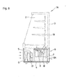
- FIG. 5 is an explanatory view explaining a refrigeration unit of another refrigerant system according to the present invention.
- a refrigeration unit 9 of a refrigerant system of the present invention shown in FIG. 5 is the same as in the refrigerant system 1 of the present invention shown in FIG. 1 except that elongated four exhaust passages 25 are penetratingly provided at positions of the unit base 4 corresponding to the portion of the air passage T through which most of exhaust heat-exchanged by the gas cooler 6 passes and the exhaust heat-exchanged by the gas cooler 6 passes through the exhaust passages 25 to be discharged outside.
- the refrigeration unit 9 of the refrigerant system of the present invention has the same actions and effects as the refrigerant system 1 of the present invention.
- the exhaust heat-exchanged by the gas cooler 6 well flows without stagnation and passes through the exhaust passage 25 and exhaust outlet 9A, and can be discharged outside. Accordingly, refrigerant gas can be sufficiently cooled in the gas cooler 6 and the durability of the compressor 5 can be improved without causing an overload state in the compressor 5 and an increase in operation power.
- FIG. 6 is an explanatory view explaining another refrigerant system according to the present invention.
- a refrigerant system (showcase) 1C of the present invention shown in FIG. 6 is the same as the refrigerant systems of the present invention shown in FIGS. 1 and 5 except that the refrigerant system 1C comprises a heat insulating housing 3 provided with an accommodating space 2 inside, and a refrigeration unit 9 fixed to a predetermined position of a lower portion of the heat insulating housing 3, in which a compressor 5, a gas cooler 6, an internal heat exchanger and restriction means not shown, are disposed on a unit base 4 accommodated in a box 9B removably, a plurality of supporting columns 7B are fixedly provided on the unit base 4 at intervals, a heat insulating case 7A is fixed onto the supporting columns 7B, an evaporator 8 is accommodated in the heat insulating case 7A, and the gas cooler 6 and the heat insulating case 7A are disposed so that exhaust heat-exchanged by the gas cooler 6 moves
- the exhaust heat-exchanged by the gas cooler 6 passes through an air passage T and is discharged from an exhaust outlet 9A to the outside and at the same time discharged from an exhaust passage 25 penetratingly provided in the unit base 4 and from an exhaust outlet 25A penetratingly provided at the position of the box 9B corresponding to the exhaust passage 25, to the outside.
- exhaust heat-exchanged by the gas cooler 6 is caused to flow without stagnation and can be discharged outside and refrigerant gas can be sufficiently cooled in the gas cooler 6, the durability of the compressor 5 can be improved without causing an overload state in the compressor 5 and an increase in operation power.
- the reference numeral 9C denotes a guide rail provided at a predetermined position on an inner side wall in the box 9B, and a guide rail 9D provided on the side of the compressor 5, the gas cooler 6, the heat insulating case 7A and the like disposed on the unit base 4, is slidably accommodated in the guide rail 9C.
- the reference numeral 9E denotes a handle fixed to the front end of the guide rail 9D. In the refrigerant system 1C of the present invention when the handle 9E is pulled this side, it can be easily pulled out while placing the compressor 5, the gas cooler 6, the heat insulating case 7A and the like on the unit base 4. After replacing parts and repairing, they are restored and can be attached.
- the box 9B can be easily attached to the heat insulating housing 3 or removed therefrom.
- a refrigeration unit 9 formed in this company is attached to a heat insulating housing 3 formed by other company and assembled to manufacture the refrigerant system 1C of the present invention. Further, after removing the refrigeration unit 9 from the refrigerant system 1C and repaired, the refrigeration unit 9 is attached again and can be reassembled.
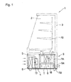
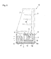
- FIG. 7 is an explanatory view explaining another refrigerant system of the present invention.
- a refrigerant system of the present invention is used in a vending machine, a refrigerator, a showcase or the like.
- a refrigerant system 1D (showcase) of the present invention comprises a heat insulating housing 3 provided with an accommodating space 2 inside, and a refrigeration unit 9 attached to a lower portion of the heat insulating housing 3, in which a compressor 5, a gas cooler 6, an internal heat exchanger 10, and a restriction means 16 are disposed on a unit base 4, a plurality of supporting columns 7B are fixedly provided on the unit base 4 at intervals, a heat insulating case 7A is set on the supporting columns 7B, an air passage T is formed between the unit base 4 and the heat insulating 7A, an evaporator 8 accommodated in the heat insulating case 7A is disposed, and the gas cooler 6 and the heat insulating case 7A are disposed so that exhaust heat-exchanged by the gas cooler 6 moves toward the
- the internal heat exchanger 10 is composed of a double pipe consisting of an outer side tube 10A and an inner side tube 10B and is provided for providing the heat insulating case 7A with heat insulation so as to be embedded in a heat insulating material layer 7C provided around the heat insulating case 7A.
- a refrigerant heat-dissipated by an air cooling system with the gas cooler 6 is passed through the inner side tube 10B of the internal heat exchanger 10 and a low pressure side refrigerant, which flows out of the evaporator 8, is passed through the outer side tube 10A whereby heat exchange is performed.
- a low pressure side refrigerant which flows out of the evaporator 8
- the reference numeral 17 denotes a fan for a gas cooler 6
- the reference numeral 18 denotes a fan for the evaporator 8
- the reference numerals 9A denotes an exhaust outlet
- the reference numeral 19 denotes an accommodating shelf for accommodating articles. Since a plurality of supporting columns 7B are fixedly provided on the unit base 4 at intervals and the heat insulating case 7A is set on the supporting columns 7B, an air passage T is formed between the unit base 4 and the heat insulating case 7A.
- the reference numeral 5 denotes an internal intermediate pressure type multi-stage (two stage) compressing rotary compressor as shown in FIG. 2, and comprises a motor-drive element 14 in a closed vessel 12, and a lower stage rotary compressing element 32 and an upper stage rotary compressing element 34, driven by a rotating shaft 11 of the motor-drive element 14.
- the compressor 5 compresses refrigerant gas sucked through a refrigerant introduction pipe 94 with the lower stage rotary compressing element 32 and discharges it into the closed vessel 12.
- intermediate pressure refrigerant gas in the closed vessel 12 is once discharged to an intermediate cooling circuit 150A through a refrigerant introduction pipe 92.
- the intermediate cooling circuit 150A is provided so that refrigerant gas passes through an intermediate cooling heat exchanger 150B, and then the refrigerant gas is air-cooled and sucked into the upper stage rotary compressing element 34 through the refrigerant introduction pipe 92.
- the refrigerant high pressurized by the second stage compression is discharged through a refrigerant discharge pipe 96 and is cooled by a gas cooler 6.
- refrigerant emitted from the gas cooler 6 was heat-exchanged with refrigerant emitted from an evaporator 8 by an internal heat exchanger 10, it passes through a restriction means 16 and enters the evaporator 8. Then after the refrigerant was evaporated, it passes through the internal heat exchanger 10 again and is sucked into the lower stage rotary compressing element 32 through the refrigerant introduction pipe 94.
- a refrigerant (a state of 2 in FIG. 3) compressed (while obtaining enthalpy ⁇ h3) by the lower stage rotary compressing element 32 to have intermediate pressure and discharged into the closed vessel 12 comes out of the refrigerant introduction pipe 92 and flows into the intermediate cooling circuit 150A. Then, the refrigerant flows into an intermediate cooling heat exchanger 150B through which the intermediate cooling circuit 150A passes, and is heat-dissipated there by an air-cooling system (a state of 3 in FIG. 3). The intermediate pressure refrigerant loses enthalpy ⁇ h1 in the intermediate cooling heat exchanger 150B as shown in FIG. 3.
- the refrigerant is sucked into the upper stage rotary compressing element 34 and the second stage compression is performed to obtain a high-pressure and temperature refrigerant gas, which is discharged to the outside from the refrigerant discharge pipe 96. At this time the refrigerant is compressed to an appropriate super critical pressure (a state of 4 in FIG. 3).
- the refrigerant gas discharged from the refrigerant discharge pipe 96 flows into the gas cooler 6 and is heat-dissipated there by an air-cooling system (a state of 5' in FIG. 3). After that the refrigerant gas passes through the inner side tube 10B of the internal heat exchanger 10. The heat of the refrigerant, which passes through the outer side tube 10A of the internal heat exchanger 10, is taken by a low pressure side refrigerant to be more cooled (a state of 5 in FIG. 3) (enthalpy is lost by ⁇ h2). After that the refrigerant is reduced in the pressure by the restriction means 16 while becoming in a gas/liquid mixture state in the process (a state of 6 in FIG.
- the refrigerant emitted from the evaporator 8 passes through the outer side tube 10A of the internal heat exchanger 10 and takes heat from the high-pressure side refrigerant there to be heated (a state of 1 in FIG. 3) (enthalpy is obtained by ⁇ h2). Then the refrigerant is heated by the internal heat exchanger 10 and is perfectly gasified. The gasified refrigerant repeats a cycle where it is sucked into the lower stage rotary compressing element 32 of the rotary compressor 5 from the refrigerant introduction pipe 94.
- the refrigerant evaporated by the evaporator 8 exhibits a cooling action by heat absorption from air, and cooled air is introduced into the accommodating space 2 of the heat insulating housing 3 by the fan 18 as shown by the arrow and is circulated.
- the exhaust heat-exchanged by the gas cooler 6 passes through the air passage T as shown by the arrow and is discharged to the outside from the exhaust outlet 9A.
- the internal heat exchanger 10 is arranged in such a manner that it is embedded in a heat insulating material layer 7C formed of closed-cell polyurethane or the like provided in outer periphery of the heat insulating case 7A to be provided with a heat insulating property, the heat exchanging efficiency of the internal heat exchanger 10 can be improved and at the same time the generation of condensation on a surface of the outer side tube 10A of the internal heat exchanger 10 can be prevented.
- the refrigerant system has the same features as the refrigerant system 1D of the present invention shown in FIG. 7 except that a refrigeration unit 9 is the same as the refrigeration unit 9 of the refrigerant system according to the present invention shown in FIG. 5.
- a refrigeration unit 9 is the same as the refrigeration unit 9 of the refrigerant system according to the present invention shown in FIG. 5.
- elongated four exhaust passages 25 are penetratingly provided at positions of the unit base 4 corresponding to the portion of the air passage T through which most of exhaust heat-exchanged by the gas cooler 6 passes and the exhaust heat-exchanged by the gas cooler 6 passes through the exhaust passages 25 to be discharged outside, as shown in FIG. 5.
- the refrigeration unit 9 of the refrigerant system of the sixth embodiment in the present invention has the same actions and effects as the case of the refrigerant system 1D of the present invention. Further the exhaust heat-exchanged by the gas cooler 6 well flows without stagnation and passes through the exhaust passage T and the exhaust outlet 9A, and can be discharged outside. Accordingly, refrigerant gas can be sufficiently cooled in the gas cooler 6 and the durability of the compressor 5 can be improved without causing an overload state in the compressor 5 and an increase in operation power.
Landscapes
- Engineering & Computer Science (AREA)
- Physics & Mathematics (AREA)
- Mechanical Engineering (AREA)
- Thermal Sciences (AREA)
- General Engineering & Computer Science (AREA)
- Chemical & Material Sciences (AREA)
- Combustion & Propulsion (AREA)
- Chemical Kinetics & Catalysis (AREA)
- Devices That Are Associated With Refrigeration Equipment (AREA)
- Other Air-Conditioning Systems (AREA)
- Details Of Measuring And Other Instruments (AREA)
Applications Claiming Priority (4)
| Application Number | Priority Date | Filing Date | Title |
|---|---|---|---|
| JP2004032509 | 2004-02-09 | ||
| JP2004032509A JP4318562B2 (ja) | 2004-02-09 | 2004-02-09 | 冷媒装置 |
| JP2004032511 | 2004-02-09 | ||
| JP2004032511A JP2005221206A (ja) | 2004-02-09 | 2004-02-09 | 冷媒装置 |
Publications (2)
| Publication Number | Publication Date |
|---|---|
| EP1562012A1 true EP1562012A1 (de) | 2005-08-10 |
| EP1562012B1 EP1562012B1 (de) | 2009-09-09 |
Family
ID=34680697
Family Applications (1)
| Application Number | Title | Priority Date | Filing Date |
|---|---|---|---|
| EP05002353A Expired - Lifetime EP1562012B1 (de) | 2004-02-09 | 2005-02-04 | Kühlsystem |
Country Status (7)
| Country | Link |
|---|---|
| US (1) | US7251949B2 (de) |
| EP (1) | EP1562012B1 (de) |
| KR (1) | KR101043826B1 (de) |
| CN (1) | CN1654909A (de) |
| AT (1) | ATE442561T1 (de) |
| DE (1) | DE602005016476D1 (de) |
| TW (1) | TWI325949B (de) |
Cited By (2)
| Publication number | Priority date | Publication date | Assignee | Title |
|---|---|---|---|---|
| EP1669707A3 (de) * | 2004-12-07 | 2006-07-19 | Sanyo Electric Co., Ltd. | Kühleinrichtung |
| WO2013091899A3 (de) * | 2011-12-23 | 2013-10-17 | Gea Bock Gmbh | Verdichter |
Families Citing this family (17)
| Publication number | Priority date | Publication date | Assignee | Title |
|---|---|---|---|---|
| US20080256974A1 (en) * | 2005-03-18 | 2008-10-23 | Carrier Commercial Refrigeration, Inc. | Condensate Heat Transfer for Transcritical Carbon Dioxide Refrigeration System |
| JP5097420B2 (ja) * | 2007-03-15 | 2012-12-12 | ホシザキ電機株式会社 | 自動製氷機 |
| CN101413748A (zh) * | 2007-10-17 | 2009-04-22 | 开利公司 | 整机展示柜系统 |
| ES2685028T3 (es) * | 2007-11-30 | 2018-10-05 | Daikin Industries, Ltd. | Aparato de refrigeración |
| JP5165440B2 (ja) * | 2008-03-31 | 2013-03-21 | ホシザキ電機株式会社 | 貯氷庫を装備する製氷機 |
| JP2010057806A (ja) * | 2008-09-05 | 2010-03-18 | Sanyo Electric Co Ltd | 低温ショーケース |
| DE102009056423A1 (de) * | 2009-09-03 | 2011-03-10 | Liebherr-Hausgeräte Ochsenhausen GmbH | Unterbaugruppenelement für ein Kühl- und/oder Gefriergerät sowie Kühl- und/oder Gefriergerät |
| KR101280381B1 (ko) * | 2009-11-18 | 2013-07-01 | 엘지전자 주식회사 | 히트 펌프 |
| US20120180986A1 (en) * | 2011-01-18 | 2012-07-19 | Mathews Thomas J | Modular cooling and heating systems |
| JP5899406B2 (ja) * | 2011-07-22 | 2016-04-06 | パナソニックIpマネジメント株式会社 | 冷蔵庫 |
| DE102012201023A1 (de) | 2012-01-24 | 2013-07-25 | BSH Bosch und Siemens Hausgeräte GmbH | Haushaltskältegerät mit einem Innenbehälter und einem Sockel |
| JP5472391B2 (ja) * | 2012-07-31 | 2014-04-16 | ダイキン工業株式会社 | コンテナ用冷凍装置 |
| CN103632444A (zh) * | 2012-08-29 | 2014-03-12 | 鸿富锦精密工业(深圳)有限公司 | 自动售货机 |
| US10188224B2 (en) * | 2015-03-03 | 2019-01-29 | Killion Industries, Inc. | Refrigerated case with a self-contained condensate removal system and leak detection |
| CN107830673A (zh) * | 2017-10-31 | 2018-03-23 | 青岛海尔特种电冰柜有限公司 | 制冷设备 |
| KR20230009089A (ko) | 2021-07-08 | 2023-01-17 | 엘지전자 주식회사 | 저장고 |
| US20250102204A1 (en) * | 2022-01-14 | 2025-03-27 | Panasonic Intellectual Property Management Co., Ltd. | Freezing apparatus |
Citations (5)
| Publication number | Priority date | Publication date | Assignee | Title |
|---|---|---|---|---|
| US5417079A (en) * | 1992-07-01 | 1995-05-23 | The Coca-Cola Company | Modular refrigeration apparatus |
| JPH10148450A (ja) * | 1996-11-19 | 1998-06-02 | Matsushita Refrig Co Ltd | 冷蔵庫 |
| EP0928934A2 (de) * | 1998-01-09 | 1999-07-14 | Whirlpool Corporation | Haushaltkühlschrank |
| JP2001116376A (ja) * | 1999-10-20 | 2001-04-27 | Sharp Corp | 超臨界蒸気圧縮式冷凍サイクル |
| EP1344938A2 (de) * | 2002-03-13 | 2003-09-17 | Sanyo Electric Co., Ltd. | Mehrstufiger Rotationsverdichter und eine Kühlvorrichtung |
Family Cites Families (26)
| Publication number | Priority date | Publication date | Assignee | Title |
|---|---|---|---|---|
| NL288796A (de) * | 1962-02-21 | |||
| US3255599A (en) | 1965-01-14 | 1966-06-14 | Elmwood Products Inc | Method and apparatus for freezing food and other perishables |
| JPS5873171A (ja) | 1981-10-28 | 1983-05-02 | Toshiba Corp | 極低温容器 |
| JP2581058B2 (ja) * | 1987-03-05 | 1997-02-12 | アイシン精機株式会社 | 再液化装置 |
| JPS63297983A (ja) | 1987-05-29 | 1988-12-05 | Hitachi Ltd | 低温保冷装置 |
| JPH01111183A (ja) | 1987-10-23 | 1989-04-27 | Hitachi Ltd | 液化ガス貯蔵容器 |
| JPH01159576A (ja) | 1987-12-16 | 1989-06-22 | Hitachi Ltd | クライオスタツト |
| JPH0633854B2 (ja) | 1988-11-01 | 1994-05-02 | 工業技術院長 | 蒸発防止装置 |
| EP0366818A1 (de) * | 1988-11-02 | 1990-05-09 | Leybold Aktiengesellschaft | Kryostat mit einem Flüssig-Stickstoff (LN2)-Bad |
| CA2003062C (en) | 1988-11-18 | 1998-09-29 | Kishio Yokouchi | Production and use of coolant in cryogenic devices |
| JPH0796920B2 (ja) | 1991-08-23 | 1995-10-18 | 岩谷産業株式会社 | 機器冷却用冷媒ガス取出装置 |
| JPH07159017A (ja) * | 1993-11-30 | 1995-06-20 | Sanyo Electric Co Ltd | 冷却貯蔵庫 |
| JP3503206B2 (ja) | 1994-09-09 | 2004-03-02 | 株式会社村田製作所 | 積層セラミック電子部品およびその製造方法 |
| JP2844433B2 (ja) | 1995-05-30 | 1999-01-06 | 岩谷産業株式会社 | 理化学機器冷却用液化ガスの再液化装置 |
| JP3675910B2 (ja) * | 1995-10-02 | 2005-07-27 | 三洋電機株式会社 | 冷却貯蔵庫 |
| JPH1019401A (ja) | 1996-07-01 | 1998-01-23 | Sanden Corp | 冷凍空調機 |
| JP3314859B2 (ja) | 1996-09-20 | 2002-08-19 | 株式会社富士通ゼネラル | 一体型空気調和機 |
| JP3096969B2 (ja) | 1997-03-07 | 2000-10-10 | 岩谷産業株式会社 | 理化学機器冷却用液化ガスの再液化装置 |
| JP2001116736A (ja) | 1999-10-21 | 2001-04-27 | Sumika Chemical Analysis Service Ltd | エストロゲンの分析方法 |
| DE10018169C5 (de) | 2000-04-12 | 2005-07-21 | Siemens Ag | Vorrichtung zur Kühlung mindestens eines elektrischen Betriebselements in mindestens einem Kryostaten |
| US6418735B1 (en) * | 2000-11-15 | 2002-07-16 | Carrier Corporation | High pressure regulation in transcritical vapor compression cycles |
| JP2003056969A (ja) | 2001-08-13 | 2003-02-26 | Hoshizaki Electric Co Ltd | 冷凍機ユニット |
| JP2003065651A (ja) | 2001-08-21 | 2003-03-05 | Hoshizaki Electric Co Ltd | 冷凍機ユニット |
| JP3983115B2 (ja) * | 2002-06-27 | 2007-09-26 | 三洋電機株式会社 | Co2冷媒を用いた冷媒回路 |
| US20050172654A1 (en) * | 2003-11-20 | 2005-08-11 | Hussmann Corporation | Modular refrigeration unit |
| GB2450755B (en) | 2007-07-06 | 2012-02-29 | Greenfield Energy Ltd | Geothermal energy system and method of operation |
-
2005
- 2005-01-19 TW TW094101506A patent/TWI325949B/zh not_active IP Right Cessation
- 2005-02-03 KR KR1020050009782A patent/KR101043826B1/ko not_active Expired - Fee Related
- 2005-02-04 AT AT05002353T patent/ATE442561T1/de not_active IP Right Cessation
- 2005-02-04 EP EP05002353A patent/EP1562012B1/de not_active Expired - Lifetime
- 2005-02-04 DE DE602005016476T patent/DE602005016476D1/de not_active Expired - Lifetime
- 2005-02-04 CN CNA2005100079762A patent/CN1654909A/zh active Pending
- 2005-02-08 US US11/053,200 patent/US7251949B2/en not_active Expired - Fee Related
Patent Citations (5)
| Publication number | Priority date | Publication date | Assignee | Title |
|---|---|---|---|---|
| US5417079A (en) * | 1992-07-01 | 1995-05-23 | The Coca-Cola Company | Modular refrigeration apparatus |
| JPH10148450A (ja) * | 1996-11-19 | 1998-06-02 | Matsushita Refrig Co Ltd | 冷蔵庫 |
| EP0928934A2 (de) * | 1998-01-09 | 1999-07-14 | Whirlpool Corporation | Haushaltkühlschrank |
| JP2001116376A (ja) * | 1999-10-20 | 2001-04-27 | Sharp Corp | 超臨界蒸気圧縮式冷凍サイクル |
| EP1344938A2 (de) * | 2002-03-13 | 2003-09-17 | Sanyo Electric Co., Ltd. | Mehrstufiger Rotationsverdichter und eine Kühlvorrichtung |
Non-Patent Citations (2)
| Title |
|---|
| PATENT ABSTRACTS OF JAPAN vol. 1998, no. 11 30 September 1998 (1998-09-30) * |
| PATENT ABSTRACTS OF JAPAN vol. 2000, no. 21 3 August 2001 (2001-08-03) * |
Cited By (3)
| Publication number | Priority date | Publication date | Assignee | Title |
|---|---|---|---|---|
| EP1669707A3 (de) * | 2004-12-07 | 2006-07-19 | Sanyo Electric Co., Ltd. | Kühleinrichtung |
| US8424332B2 (en) | 2004-12-07 | 2013-04-23 | Sanyo Electric Co., Ltd. | Modular refrigerator installed by hooks |
| WO2013091899A3 (de) * | 2011-12-23 | 2013-10-17 | Gea Bock Gmbh | Verdichter |
Also Published As
| Publication number | Publication date |
|---|---|
| US20050217296A1 (en) | 2005-10-06 |
| US7251949B2 (en) | 2007-08-07 |
| EP1562012B1 (de) | 2009-09-09 |
| CN1654909A (zh) | 2005-08-17 |
| TWI325949B (en) | 2010-06-11 |
| ATE442561T1 (de) | 2009-09-15 |
| KR20060041613A (ko) | 2006-05-12 |
| TW200530543A (en) | 2005-09-16 |
| DE602005016476D1 (de) | 2009-10-22 |
| KR101043826B1 (ko) | 2011-06-22 |
Similar Documents
| Publication | Publication Date | Title |
|---|---|---|
| EP1562012B1 (de) | Kühlsystem | |
| US20070056312A1 (en) | Cooling System | |
| WO2003004948A1 (fr) | Pompe a chaleur | |
| JP2009133593A (ja) | 冷却装置 | |
| US7225635B2 (en) | Refrigerant cycle apparatus | |
| JP5542722B2 (ja) | 冷凍装置 | |
| US6385995B1 (en) | Apparatus having a refrigeration circuit | |
| KR100836824B1 (ko) | 냉매 사이클 장치 | |
| JPH11351680A (ja) | 冷房装置 | |
| JP5490468B2 (ja) | 冷却貯蔵庫及び冷却貯蔵庫の冷凍装置の冷媒漏れ検査方法 | |
| JP2000097177A (ja) | 回転式圧縮機及び冷凍回路 | |
| JP4318562B2 (ja) | 冷媒装置 | |
| AU2007201236B2 (en) | Manufacturing method of transition critical refrigerating cycle device | |
| US20060168997A1 (en) | Refrigerating device and refrigerator | |
| JP2007093105A (ja) | 冷凍装置及び気液分離器 | |
| JP3462785B2 (ja) | 冷凍装置 | |
| KR100782973B1 (ko) | 압축기 시험장치 | |
| JP2005221206A (ja) | 冷媒装置 | |
| JP2000105004A (ja) | 回転式圧縮機 | |
| JP7542579B2 (ja) | 冷凍サイクル装置 | |
| CN104567139A (zh) | 制冷循环装置及空气调节装置 | |
| JP2004294059A (ja) | ヒートポンプ装置 | |
| KR20140052432A (ko) | 차량용 스털링 냉동기 | |
| JP4967256B2 (ja) | 冷凍サイクルシステムおよび当該冷凍サイクルシステムに適した作動流体 | |
| JP2008241205A (ja) | 空気調和機 |
Legal Events
| Date | Code | Title | Description |
|---|---|---|---|
| PUAI | Public reference made under article 153(3) epc to a published international application that has entered the european phase |
Free format text: ORIGINAL CODE: 0009012 |
|
| AK | Designated contracting states |
Kind code of ref document: A1 Designated state(s): AT BE BG CH CY CZ DE DK EE ES FI FR GB GR HU IE IS IT LI LT LU MC NL PL PT RO SE SI SK TR |
|
| AX | Request for extension of the european patent |
Extension state: AL BA HR LV MK YU |
|
| 17P | Request for examination filed |
Effective date: 20050930 |
|
| AKX | Designation fees paid |
Designated state(s): AT BE BG CH CY CZ DE DK EE ES FI FR GB GR HU IE IS IT LI LT LU MC NL PL PT RO SE SI SK TR |
|
| 17Q | First examination report despatched |
Effective date: 20080402 |
|
| GRAP | Despatch of communication of intention to grant a patent |
Free format text: ORIGINAL CODE: EPIDOSNIGR1 |
|
| GRAS | Grant fee paid |
Free format text: ORIGINAL CODE: EPIDOSNIGR3 |
|
| GRAA | (expected) grant |
Free format text: ORIGINAL CODE: 0009210 |
|
| AK | Designated contracting states |
Kind code of ref document: B1 Designated state(s): AT BE BG CH CY CZ DE DK EE ES FI FR GB GR HU IE IS IT LI LT LU MC NL PL PT RO SE SI SK TR |
|
| REG | Reference to a national code |
Ref country code: GB Ref legal event code: FG4D |
|
| REG | Reference to a national code |
Ref country code: CH Ref legal event code: EP |
|
| REG | Reference to a national code |
Ref country code: IE Ref legal event code: FG4D |
|
| REF | Corresponds to: |
Ref document number: 602005016476 Country of ref document: DE Date of ref document: 20091022 Kind code of ref document: P |
|
| PG25 | Lapsed in a contracting state [announced via postgrant information from national office to epo] |
Ref country code: SE Free format text: LAPSE BECAUSE OF FAILURE TO SUBMIT A TRANSLATION OF THE DESCRIPTION OR TO PAY THE FEE WITHIN THE PRESCRIBED TIME-LIMIT Effective date: 20090909 Ref country code: LT Free format text: LAPSE BECAUSE OF FAILURE TO SUBMIT A TRANSLATION OF THE DESCRIPTION OR TO PAY THE FEE WITHIN THE PRESCRIBED TIME-LIMIT Effective date: 20090909 Ref country code: FI Free format text: LAPSE BECAUSE OF FAILURE TO SUBMIT A TRANSLATION OF THE DESCRIPTION OR TO PAY THE FEE WITHIN THE PRESCRIBED TIME-LIMIT Effective date: 20090909 |
|
| NLV1 | Nl: lapsed or annulled due to failure to fulfill the requirements of art. 29p and 29m of the patents act | ||
| LTIE | Lt: invalidation of european patent or patent extension |
Effective date: 20090909 |
|
| PG25 | Lapsed in a contracting state [announced via postgrant information from national office to epo] |
Ref country code: PL Free format text: LAPSE BECAUSE OF FAILURE TO SUBMIT A TRANSLATION OF THE DESCRIPTION OR TO PAY THE FEE WITHIN THE PRESCRIBED TIME-LIMIT Effective date: 20090909 Ref country code: SI Free format text: LAPSE BECAUSE OF FAILURE TO SUBMIT A TRANSLATION OF THE DESCRIPTION OR TO PAY THE FEE WITHIN THE PRESCRIBED TIME-LIMIT Effective date: 20090909 Ref country code: NL Free format text: LAPSE BECAUSE OF FAILURE TO SUBMIT A TRANSLATION OF THE DESCRIPTION OR TO PAY THE FEE WITHIN THE PRESCRIBED TIME-LIMIT Effective date: 20090909 |
|
| PG25 | Lapsed in a contracting state [announced via postgrant information from national office to epo] |
Ref country code: CY Free format text: LAPSE BECAUSE OF FAILURE TO SUBMIT A TRANSLATION OF THE DESCRIPTION OR TO PAY THE FEE WITHIN THE PRESCRIBED TIME-LIMIT Effective date: 20090909 |
|
| PG25 | Lapsed in a contracting state [announced via postgrant information from national office to epo] |
Ref country code: RO Free format text: LAPSE BECAUSE OF FAILURE TO SUBMIT A TRANSLATION OF THE DESCRIPTION OR TO PAY THE FEE WITHIN THE PRESCRIBED TIME-LIMIT Effective date: 20090909 Ref country code: IS Free format text: LAPSE BECAUSE OF FAILURE TO SUBMIT A TRANSLATION OF THE DESCRIPTION OR TO PAY THE FEE WITHIN THE PRESCRIBED TIME-LIMIT Effective date: 20100109 Ref country code: CZ Free format text: LAPSE BECAUSE OF FAILURE TO SUBMIT A TRANSLATION OF THE DESCRIPTION OR TO PAY THE FEE WITHIN THE PRESCRIBED TIME-LIMIT Effective date: 20090909 Ref country code: EE Free format text: LAPSE BECAUSE OF FAILURE TO SUBMIT A TRANSLATION OF THE DESCRIPTION OR TO PAY THE FEE WITHIN THE PRESCRIBED TIME-LIMIT Effective date: 20090909 Ref country code: ES Free format text: LAPSE BECAUSE OF FAILURE TO SUBMIT A TRANSLATION OF THE DESCRIPTION OR TO PAY THE FEE WITHIN THE PRESCRIBED TIME-LIMIT Effective date: 20091220 Ref country code: PT Free format text: LAPSE BECAUSE OF FAILURE TO SUBMIT A TRANSLATION OF THE DESCRIPTION OR TO PAY THE FEE WITHIN THE PRESCRIBED TIME-LIMIT Effective date: 20100111 |
|
| PG25 | Lapsed in a contracting state [announced via postgrant information from national office to epo] |
Ref country code: SK Free format text: LAPSE BECAUSE OF FAILURE TO SUBMIT A TRANSLATION OF THE DESCRIPTION OR TO PAY THE FEE WITHIN THE PRESCRIBED TIME-LIMIT Effective date: 20090909 |
|
| PG25 | Lapsed in a contracting state [announced via postgrant information from national office to epo] |
Ref country code: BE Free format text: LAPSE BECAUSE OF FAILURE TO SUBMIT A TRANSLATION OF THE DESCRIPTION OR TO PAY THE FEE WITHIN THE PRESCRIBED TIME-LIMIT Effective date: 20090909 Ref country code: AT Free format text: LAPSE BECAUSE OF FAILURE TO SUBMIT A TRANSLATION OF THE DESCRIPTION OR TO PAY THE FEE WITHIN THE PRESCRIBED TIME-LIMIT Effective date: 20090909 |
|
| PLBE | No opposition filed within time limit |
Free format text: ORIGINAL CODE: 0009261 |
|
| STAA | Information on the status of an ep patent application or granted ep patent |
Free format text: STATUS: NO OPPOSITION FILED WITHIN TIME LIMIT |
|
| PG25 | Lapsed in a contracting state [announced via postgrant information from national office to epo] |
Ref country code: DK Free format text: LAPSE BECAUSE OF FAILURE TO SUBMIT A TRANSLATION OF THE DESCRIPTION OR TO PAY THE FEE WITHIN THE PRESCRIBED TIME-LIMIT Effective date: 20090909 |
|
| 26N | No opposition filed |
Effective date: 20100610 |
|
| REG | Reference to a national code |
Ref country code: CH Ref legal event code: PL |
|
| PG25 | Lapsed in a contracting state [announced via postgrant information from national office to epo] |
Ref country code: GR Free format text: LAPSE BECAUSE OF FAILURE TO SUBMIT A TRANSLATION OF THE DESCRIPTION OR TO PAY THE FEE WITHIN THE PRESCRIBED TIME-LIMIT Effective date: 20091210 Ref country code: CH Free format text: LAPSE BECAUSE OF NON-PAYMENT OF DUE FEES Effective date: 20100228 Ref country code: MC Free format text: LAPSE BECAUSE OF NON-PAYMENT OF DUE FEES Effective date: 20100301 Ref country code: LI Free format text: LAPSE BECAUSE OF NON-PAYMENT OF DUE FEES Effective date: 20100228 |
|
| PG25 | Lapsed in a contracting state [announced via postgrant information from national office to epo] |
Ref country code: IE Free format text: LAPSE BECAUSE OF NON-PAYMENT OF DUE FEES Effective date: 20100204 |
|
| PG25 | Lapsed in a contracting state [announced via postgrant information from national office to epo] |
Ref country code: IT Free format text: LAPSE BECAUSE OF FAILURE TO SUBMIT A TRANSLATION OF THE DESCRIPTION OR TO PAY THE FEE WITHIN THE PRESCRIBED TIME-LIMIT Effective date: 20090909 |
|
| PGFP | Annual fee paid to national office [announced via postgrant information from national office to epo] |
Ref country code: DE Payment date: 20120131 Year of fee payment: 8 |
|
| PGFP | Annual fee paid to national office [announced via postgrant information from national office to epo] |
Ref country code: GB Payment date: 20120201 Year of fee payment: 8 |
|
| PG25 | Lapsed in a contracting state [announced via postgrant information from national office to epo] |
Ref country code: BG Free format text: LAPSE BECAUSE OF FAILURE TO SUBMIT A TRANSLATION OF THE DESCRIPTION OR TO PAY THE FEE WITHIN THE PRESCRIBED TIME-LIMIT Effective date: 20090909 Ref country code: HU Free format text: LAPSE BECAUSE OF FAILURE TO SUBMIT A TRANSLATION OF THE DESCRIPTION OR TO PAY THE FEE WITHIN THE PRESCRIBED TIME-LIMIT Effective date: 20100310 Ref country code: LU Free format text: LAPSE BECAUSE OF NON-PAYMENT OF DUE FEES Effective date: 20100204 |
|
| PG25 | Lapsed in a contracting state [announced via postgrant information from national office to epo] |
Ref country code: TR Free format text: LAPSE BECAUSE OF FAILURE TO SUBMIT A TRANSLATION OF THE DESCRIPTION OR TO PAY THE FEE WITHIN THE PRESCRIBED TIME-LIMIT Effective date: 20090909 |
|
| PGFP | Annual fee paid to national office [announced via postgrant information from national office to epo] |
Ref country code: FR Payment date: 20130318 Year of fee payment: 9 |
|
| GBPC | Gb: european patent ceased through non-payment of renewal fee |
Effective date: 20130204 |
|
| REG | Reference to a national code |
Ref country code: DE Ref legal event code: R119 Ref document number: 602005016476 Country of ref document: DE Effective date: 20130903 |
|
| REG | Reference to a national code |
Ref country code: FR Ref legal event code: ST Effective date: 20131203 |
|
| PG25 | Lapsed in a contracting state [announced via postgrant information from national office to epo] |
Ref country code: GB Free format text: LAPSE BECAUSE OF NON-PAYMENT OF DUE FEES Effective date: 20130204 Ref country code: FR Free format text: LAPSE BECAUSE OF NON-PAYMENT OF DUE FEES Effective date: 20130228 Ref country code: DE Free format text: LAPSE BECAUSE OF NON-PAYMENT OF DUE FEES Effective date: 20130903 |