EP1562018A1 - Tube d'échangeur de chaleur, échangeur de chaleur et son utilisation - Google Patents
Tube d'échangeur de chaleur, échangeur de chaleur et son utilisation Download PDFInfo
- Publication number
- EP1562018A1 EP1562018A1 EP04002333A EP04002333A EP1562018A1 EP 1562018 A1 EP1562018 A1 EP 1562018A1 EP 04002333 A EP04002333 A EP 04002333A EP 04002333 A EP04002333 A EP 04002333A EP 1562018 A1 EP1562018 A1 EP 1562018A1
- Authority
- EP
- European Patent Office
- Prior art keywords
- heat exchanger
- exchanger tube
- layer
- cooling medium
- medium
- Prior art date
- Legal status (The legal status is an assumption and is not a legal conclusion. Google has not performed a legal analysis and makes no representation as to the accuracy of the status listed.)
- Withdrawn
Links
- 239000002826 coolant Substances 0.000 claims abstract description 41
- 230000015572 biosynthetic process Effects 0.000 claims abstract description 16
- 239000000463 material Substances 0.000 claims description 24
- 238000000576 coating method Methods 0.000 claims description 20
- 239000011248 coating agent Substances 0.000 claims description 17
- 239000012530 fluid Substances 0.000 claims description 7
- 229920001343 polytetrafluoroethylene Polymers 0.000 claims description 7
- 239000004810 polytetrafluoroethylene Substances 0.000 claims description 7
- BPQQTUXANYXVAA-UHFFFAOYSA-N Orthosilicate Chemical compound [O-][Si]([O-])([O-])[O-] BPQQTUXANYXVAA-UHFFFAOYSA-N 0.000 claims description 5
- -1 polytetrafluoroethylene Polymers 0.000 claims description 4
- 238000011068 loading method Methods 0.000 claims description 3
- OKTJSMMVPCPJKN-UHFFFAOYSA-N Carbon Chemical compound [C] OKTJSMMVPCPJKN-UHFFFAOYSA-N 0.000 claims description 2
- 229910052799 carbon Inorganic materials 0.000 claims description 2
- 238000012546 transfer Methods 0.000 abstract description 10
- 238000000034 method Methods 0.000 description 8
- 238000009833 condensation Methods 0.000 description 6
- 230000005494 condensation Effects 0.000 description 6
- 230000000694 effects Effects 0.000 description 5
- 238000004519 manufacturing process Methods 0.000 description 5
- 238000003466 welding Methods 0.000 description 5
- 230000001070 adhesive effect Effects 0.000 description 4
- 238000004140 cleaning Methods 0.000 description 4
- 238000001816 cooling Methods 0.000 description 4
- 238000013461 design Methods 0.000 description 4
- 238000012986 modification Methods 0.000 description 3
- 230000004048 modification Effects 0.000 description 3
- 239000004809 Teflon Substances 0.000 description 2
- 229920006362 Teflon® Polymers 0.000 description 2
- 239000000654 additive Substances 0.000 description 2
- 239000003990 capacitor Substances 0.000 description 2
- 230000006735 deficit Effects 0.000 description 2
- 230000001771 impaired effect Effects 0.000 description 2
- 239000002105 nanoparticle Substances 0.000 description 2
- 239000012196 polytetrafluoroethylene based material Substances 0.000 description 2
- 238000009825 accumulation Methods 0.000 description 1
- 238000007792 addition Methods 0.000 description 1
- 239000002318 adhesion promoter Substances 0.000 description 1
- 230000002411 adverse Effects 0.000 description 1
- 230000003373 anti-fouling effect Effects 0.000 description 1
- 230000009286 beneficial effect Effects 0.000 description 1
- 230000003115 biocidal effect Effects 0.000 description 1
- 239000003139 biocide Substances 0.000 description 1
- 230000007797 corrosion Effects 0.000 description 1
- 238000005260 corrosion Methods 0.000 description 1
- 230000003247 decreasing effect Effects 0.000 description 1
- 230000000593 degrading effect Effects 0.000 description 1
- 230000001419 dependent effect Effects 0.000 description 1
- 238000011161 development Methods 0.000 description 1
- 238000000227 grinding Methods 0.000 description 1
- 238000009499 grossing Methods 0.000 description 1
- 229910010272 inorganic material Inorganic materials 0.000 description 1
- 239000011147 inorganic material Substances 0.000 description 1
- 238000009434 installation Methods 0.000 description 1
- 230000000873 masking effect Effects 0.000 description 1
- 239000002184 metal Substances 0.000 description 1
- 239000000203 mixture Substances 0.000 description 1
- 238000000465 moulding Methods 0.000 description 1
- 239000011368 organic material Substances 0.000 description 1
- 238000007789 sealing Methods 0.000 description 1
- 238000003980 solgel method Methods 0.000 description 1
- 239000000126 substance Substances 0.000 description 1
- 238000004381 surface treatment Methods 0.000 description 1
- 238000012549 training Methods 0.000 description 1
Images
Classifications
-
- F—MECHANICAL ENGINEERING; LIGHTING; HEATING; WEAPONS; BLASTING
- F28—HEAT EXCHANGE IN GENERAL
- F28F—DETAILS OF HEAT-EXCHANGE AND HEAT-TRANSFER APPARATUS, OF GENERAL APPLICATION
- F28F13/00—Arrangements for modifying heat-transfer, e.g. increasing, decreasing
- F28F13/18—Arrangements for modifying heat-transfer, e.g. increasing, decreasing by applying coatings, e.g. radiation-absorbing, radiation-reflecting; by surface treatment, e.g. polishing
-
- F—MECHANICAL ENGINEERING; LIGHTING; HEATING; WEAPONS; BLASTING
- F28—HEAT EXCHANGE IN GENERAL
- F28F—DETAILS OF HEAT-EXCHANGE AND HEAT-TRANSFER APPARATUS, OF GENERAL APPLICATION
- F28F13/00—Arrangements for modifying heat-transfer, e.g. increasing, decreasing
- F28F13/04—Arrangements for modifying heat-transfer, e.g. increasing, decreasing by preventing the formation of continuous films of condensate on heat-exchange surfaces, e.g. by promoting droplet formation
-
- F—MECHANICAL ENGINEERING; LIGHTING; HEATING; WEAPONS; BLASTING
- F28—HEAT EXCHANGE IN GENERAL
- F28F—DETAILS OF HEAT-EXCHANGE AND HEAT-TRANSFER APPARATUS, OF GENERAL APPLICATION
- F28F2245/00—Coatings; Surface treatments
- F28F2245/04—Coatings; Surface treatments hydrophobic
-
- F—MECHANICAL ENGINEERING; LIGHTING; HEATING; WEAPONS; BLASTING
- F28—HEAT EXCHANGE IN GENERAL
- F28F—DETAILS OF HEAT-EXCHANGE AND HEAT-TRANSFER APPARATUS, OF GENERAL APPLICATION
- F28F2265/00—Safety or protection arrangements; Arrangements for preventing malfunction
- F28F2265/20—Safety or protection arrangements; Arrangements for preventing malfunction for preventing development of microorganisms
Definitions
- the invention relates to a heat exchanger tube with a on an outer surface lying outside for loading with steam and an inner surface lying on an inner surface for charging with a cooling medium.
- the invention further relates to a heat exchanger with a cooling medium guide and a vapor medium guide, wherein the cooling medium guide a variety of heat exchanger tubes for guiding Has cooling medium on the inside of a heat exchanger tube, and the steam guide for acting on an outside a heat exchanger tube designed with steam medium is.
- the invention also leads to a use.
- Heat exchangers of the above type are usually used in a fluid contained in the heat medium to a fluid Transfer cooling medium. That way it cools Steam medium while the cooling medium heats up. Possibly the heat exchanger is designed so that the cooling of the vapor medium until condensation of the vapor medium leads - in this case, a heat exchanger is also called Capacitor, in particular steam condenser referred to. Heat exchanger, in particular capacitors of the type mentioned, are usually installed in power plants. There serves a fluid vapor medium usually as a working medium for Drive a turbine and gives it its kinetic energy to drive the turbine to a turbine rotor, which in turn used to drive a generator.
- This turbine exit side vapor medium is usually a heat exchanger, in particular a condenser mentioned above Kind, fed.
- the goal is usually the vapor medium to condense, possibly also its heat content after delivery continue to use the cooling medium.
- the boundary of a vapor medium guide in a heat exchanger of the above type formed by a wall, from a variety of heat exchanger tubes of the cooling medium guide is constructed.
- Other concepts look across the box Steam medium guide arranged cooling medium guides, so a steam medium guided in the steam guide is attached to the Flow past the plurality of heat exchanger tubes of the cooling medium guide got to.
- the rebuilt volume of such Heat exchangers, in particular of steam condensers, depending on Design to be kept as low as possible and optimized be that the efficiency of such heat exchangers possible good is.
- the aim of a heat exchanger is therefore, the Heat transfer in a heat exchanger tube as effective as possible, so that the contained in the vapor medium Level of heat supplied as completely as possible to the cooling medium can be lost and not otherwise lost or unintentionally remains in the vapor medium.
- a hindrance to the Heat transfer occurs z. B. by a formation of an insulating Condensation film on an outside of a heat exchanger tube.
- a hindrance of the heat transfer is so more serious, the denser an insulating condensation film of this kind on an outer surface of a heat exchanger tube is.
- the nature of such a condensation film depends on it significantly influenced by the formation of droplets or the dripping behavior from condensed vapor medium.
- a further impairment of the heat transfer takes place by a cooling medium-side deposit formation on an inner side a heat exchanger tube.
- Such a deposit formation takes place over time by being contained in the cooling medium inorganic and organic components on the inner surface Deposit a heat exchanger tube and collect.
- Various Cleaning measures can greatly increase this effect slow down, however, are laborious and can slow down the process as such do not prevent.
- the invention begins, whose task it is, a heat exchanger tube, a heat exchanger and a use specify a heat exchanger tube, in which a heat transfer from a vapor medium to a cooling medium is improved over conventional concepts.
- the task is with respect to a heat exchanger tube through a heat exchanger tube of the type mentioned in, at according to the invention, the outer surface with an adhesion of the vapor medium at the outer surface reducing is provided first layer and / or the inner surface with an adhesion of the cooling medium to the inner surface reducing second layer is provided.
- the invention is based on the consideration that for the drop formation or the dripping behavior of a vapor medium the outer surface of the heat exchanger tube, the surface tension of the pipe material is of grave importance. In addition, the invention is based on the consideration that the Coating on the inner surface of a heat exchanger tube to a considerable degree of the adhesive properties of the surface depends.
- heat exchanger tubes above kind to provide and especially in one Provide heat exchanger.
- One main reason lies among other things in that the pipes after their fabrication only with high Effort can be coated. You can also relax the production of the tubes interior coatings practically not perform more, as the tubes are usually of length Own 10 m or more.
- a heat exchanger above kind for a power plant are usually hundreds of kilometers laid by heat exchanger tubes.
- For a nuclear power plant can a heat exchanger more than 1000 km laid heat exchanger tubes exhibit.
- the outer surface and / or the inner surface of the heat exchanger tube also with the claimed functionality provided surface treatment to understand the surface of a heat exchanger tube.
- the surface of a heat exchanger tube be smoothed or polished by suitable measures.
- a layer as a coating.
- the first layer and / or the second layer formed from a number of sub-layers.
- sublayers can be used, for example, as adhesion promoter layers serve.
- adhesion promoter layers serve.
- a coating of the outer surface and a coating the inner surface of the first layer is different is formed to the second layer.
- the first layer is advantageous to do so the first layer as a the surface tension of the Pipe material on the outer surface reducing layer designed.
- a second layer is advantageous as a the formation of deposits on the inner surface of the pipe material decreasing layer configured, so to reduce the adhesive properties of the inner surface of a heat exchanger tube designed.
- the first layer is thus advantageous as the surface tension the outer surface degrading layer designed. This advantageously reduces the formation of drops and the dripping behavior of the vapor medium in a condensation thereof.
- the second layer is therefore advantageous as a the formation of a deposit designed on the inner surface reducing layer.
- a layer may be used as a biocide layer be designed.
- Next proves to be an antifouling layer as advantageous. Reduce such layers the formation of deposits and the growth of organic substances to a negligible extent.
- the invention leads to the solution of the problem in terms of Heat exchanger on a heat exchanger of the aforementioned Art in which a heat exchanger tube according to the invention to a designed above type is designed.
- the Heat exchanger tube as a longitudinally welded heat exchanger tube is trained. That is, in the heat exchanger tube a weld extends along the elongated extent of the pipe and it is in the installed condition of the pipe arranged on the upper side of the pipe cross-section.
- the layer becomes advantageous immediately before the welding process and still in the molding process of the tape to the slotted tube in Area of slit / weld removed.
- the weld seam area be ground, so that under such a Grinding process an existing layer, in particular Coating, is removed again.
- the object with regard to a use concerning the heat exchanger tube is achieved by a use according to the invention an adhesion of a fluid to a surface reducing coating material for an outer surface an outer side of a heat exchanger tube for acting with a vapor medium and for an inner surface at one Inside of the heat exchanger tube to act on a Cooling medium.
- the outer surface is one with an adhesion of the vapor medium at the outer surface reducing the first Layer is provided and / or the inner surface is with a reduce adhesion of the cooling medium to the inner surface second layer provided.
- PTFE Polytetrafluoroethylene
- organic silicate network based material for use as a layer material as proved particularly advantageous.
- Such organic silicate networks can be advantageously as outer surface consisting from nanoparticles which have the non-stick properties a surface, in particular an inner surface significantly reduce the heat exchanger tube.
- a polytetrafluoroethylene-based sheet material can be particularly beneficial on an outer surface of a Heat exchanger tube can be used.
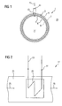
- the particularly preferred embodiment shown here of the heat exchanger tube 1 in the installed state sees a an adhesion of a fluid to a surface 3, 5 of the heat exchanger tube 1 reducing layer 7, 9 before.
- the heat exchanger tube 1 has a steam-side outer surface 3 its outer side 4 for exposure to a vapor medium 25 on and a cooling medium-side inner surface 5 at its Inner side 6 for acting on a cooling medium 27 on.
- the outer surface 3 is one with an adhesion of the vapor medium on the outer surface 3 reducing first layer 7 provided.
- the inner surface 5 is one with an adhesion of the cooling medium on the inner surface 5 reducing the second Layer 9 provided.
- the first vapor-side layer 7 is presently made of a Layered material made on a PTFE (polytetrafluoroethylene) based material is. Present will be a Mixture of teflon and other components preferred.
- the second, cooling medium-side layer 9 is present on a an organic silicate network based material. This Material was present in the formation of nanoparticles produced and exhibits according to a so-called sol-gel process so that a surface structured in the nanometer range. It has been shown that this type of coating with a second layer 9 on an inner surface 5 particularly advantageous the adhesive properties of a cooling medium and thus the deposit and accumulation of organic and inorganic Material on the inner surface 5 of the heat exchanger tube 1 prevented.
- a first layer 7 on an outer surface 3 of the heat exchanger tube 1 based on polytetrafluoroethylene has a particularly low surface tension and thus reduces the formation of drops on the Surface and as far as drops are formed, the dripping behavior is changed so that no condensation films on the outer surface 3 of the heat exchanger tube 1 can form.
- the heat exchanger tube 1 shown in this embodiment is advantageously made from a narrow band that already as such on its the inner surface 5 associated Surface with a layer 9 organic silicate network to form an inside 6 has been provided and on a the outer surface 3 associated surface with a polytetrafluoroethylene based material for forming an outside 4 has been provided.
- the narrow band in the area 11 so on its edges, later in the area 11 of the weld 13 would lie already during the coating process for formation the layers 9, 7 masked and in this embodiment then ground, so that the area 11 of the Weld 13 remained free of coating.
- the sanding step can also be omitted in the context of a modification. After the rounding of the narrow band to the slot tube in the further production step could the weld 13 at the slotted pipe to Completion of the heat exchanger tube to be attached without while adverse effects of a coating 9, 7 on to have to accept the welding process.
- a heat exchanger tube As part of a modification, a heat exchanger tube, essentially with the same manufacturing method explained above, only in the area of its three o'clock position until nine o'clock position be coated. It has been shown that in particular the area around the six o'clock position at a Heat exchanger tube particularly susceptible to corrosion and surface damage is. In particular, often remain, z. B. especially in a Emptying of the heat exchanger tube, suspended matter in the Range of the six o'clock position on the inside of the heat exchanger tube. At least the area around the six o'clock position, z. As a 45 ° angle range, a 90 ° angle range, advantageous a 120 ° angle range and in particular a 180 ° angle range or a larger angle range, respectively as part of the modification provided with a layer.
- FIG 2 shows schematically a heat exchanger 17 with a Cooling medium guide 19 and a steam medium guide 21.
- Die Cooling medium guide 19 has to guide the cooling medium 27 a Variety of in Figure 1 explained in more detail heat exchanger tubes 23, which is shown only schematically in FIG are.
- the cooling medium 27 is doing on the inside of the 6 Heat exchanger tubes 23 out.
- the steam guide 21 sees the Actuation of the outside 4 of the heat exchanger tubes 23 with a vapor medium 25 before.
- the heat transfer in heat exchanger tubes 1, 23 obstructing To avoid film formation is in a heat exchanger tube 1, 23 with a lying on an outer surface 3 Outside 4 to be exposed to a vapor medium and a lying on an inner surface 5 inside 6 to Loading with a cooling medium according to the proposed Concept provided that the outer surface 3 with a a Adhesion of the vapor on the outer surface 3 reducing is provided first layer 7 and / or the inner surface with an adhesion of the cooling medium to the inner surface 5 reducing second layer 9 is provided.
- the concept leads to a heat exchanger 17 and a use.
Landscapes
- Engineering & Computer Science (AREA)
- Physics & Mathematics (AREA)
- Thermal Sciences (AREA)
- Mechanical Engineering (AREA)
- General Engineering & Computer Science (AREA)
- Heat-Exchange Devices With Radiators And Conduit Assemblies (AREA)
Priority Applications (6)
| Application Number | Priority Date | Filing Date | Title |
|---|---|---|---|
| EP04002333A EP1562018A1 (fr) | 2004-02-03 | 2004-02-03 | Tube d'échangeur de chaleur, échangeur de chaleur et son utilisation |
| PCT/EP2005/000883 WO2005075926A1 (fr) | 2004-02-03 | 2005-01-28 | Tube d'echangeur thermique, echangeur thermique et utilisation |
| CNB2005800079671A CN100516762C (zh) | 2004-02-03 | 2005-01-28 | 热交换管、热交换器和涂层材料在热交换管上的应用 |
| US10/588,351 US7640969B2 (en) | 2004-02-03 | 2005-01-28 | Heat exchanger tube, heat exchanger and use |
| EP05701250A EP1711773A1 (fr) | 2004-02-03 | 2005-01-28 | Tube d'echangeur thermique, echangeur thermique et utilisation |
| US12/582,293 US8240364B2 (en) | 2004-02-03 | 2009-10-20 | Heat exchanger tube, heat exchanger and use |
Applications Claiming Priority (1)
| Application Number | Priority Date | Filing Date | Title |
|---|---|---|---|
| EP04002333A EP1562018A1 (fr) | 2004-02-03 | 2004-02-03 | Tube d'échangeur de chaleur, échangeur de chaleur et son utilisation |
Publications (1)
| Publication Number | Publication Date |
|---|---|
| EP1562018A1 true EP1562018A1 (fr) | 2005-08-10 |
Family
ID=34673661
Family Applications (2)
| Application Number | Title | Priority Date | Filing Date |
|---|---|---|---|
| EP04002333A Withdrawn EP1562018A1 (fr) | 2004-02-03 | 2004-02-03 | Tube d'échangeur de chaleur, échangeur de chaleur et son utilisation |
| EP05701250A Withdrawn EP1711773A1 (fr) | 2004-02-03 | 2005-01-28 | Tube d'echangeur thermique, echangeur thermique et utilisation |
Family Applications After (1)
| Application Number | Title | Priority Date | Filing Date |
|---|---|---|---|
| EP05701250A Withdrawn EP1711773A1 (fr) | 2004-02-03 | 2005-01-28 | Tube d'echangeur thermique, echangeur thermique et utilisation |
Country Status (4)
| Country | Link |
|---|---|
| US (2) | US7640969B2 (fr) |
| EP (2) | EP1562018A1 (fr) |
| CN (1) | CN100516762C (fr) |
| WO (1) | WO2005075926A1 (fr) |
Cited By (3)
| Publication number | Priority date | Publication date | Assignee | Title |
|---|---|---|---|---|
| WO2007031262A1 (fr) * | 2005-09-14 | 2007-03-22 | Behr Gmbh & Co. Kg | Echangeur thermique, en particulier echangeur thermique pour gaz d'echappement |
| WO2008119751A1 (fr) * | 2007-03-30 | 2008-10-09 | Siemens Aktiengesellschaft | Revêtement pour condenseurs de vapeur |
| DE102017129111A1 (de) * | 2017-12-07 | 2019-06-13 | Man Energy Solutions Se | Kühler eines Verdichters |
Families Citing this family (5)
| Publication number | Priority date | Publication date | Assignee | Title |
|---|---|---|---|---|
| EP1591740B8 (fr) * | 2004-04-30 | 2007-11-07 | Rabtherm AG | Echangeur de chaleur et installation de récupération de la chaleur des eaux usées |
| US20100206527A1 (en) * | 2009-02-18 | 2010-08-19 | Hu Lin-Wen | In-Situ Treatment of Metallic Surfaces |
| CN104748604B (zh) * | 2015-03-26 | 2016-07-13 | 中国科学院工程热物理研究所 | 一种带有疏水带的珠状凝结强化换热表面结构 |
| DK3415852T3 (da) * | 2016-08-05 | 2024-02-05 | Obshestvo S Ogranichennoi Otvetstvennostu Reinnolts Lab | Skal- og rørkondensator og varmevekslingsrør til en skal- og rørkondensator (varianter) |
| US20180372413A1 (en) | 2017-06-22 | 2018-12-27 | Rheem Manufacturing Company | Heat Exchanger Tubes And Tube Assembly Configurations |
Citations (6)
| Publication number | Priority date | Publication date | Assignee | Title |
|---|---|---|---|---|
| CH286241A (de) * | 1949-06-28 | 1952-10-15 | Bbc Brown Boveri & Cie | Einrichtung zur Erzielung einer Tropfenkondensation bei Kondensationsanlagen. |
| GB1042387A (en) * | 1964-03-19 | 1966-09-14 | Serck Tubes Ltd | Heat exchangers |
| GB1042386A (en) * | 1964-03-19 | 1966-09-14 | Serck Tubes Ltd | Surface condensers for steam and other vapours |
| EP0581820A1 (fr) * | 1991-04-26 | 1994-02-09 | Glynwed Plastics | Tube a structure composite metal-plastique et procede de fabrication. |
| US6337129B1 (en) * | 1997-06-02 | 2002-01-08 | Toto Ltd. | Antifouling member and antifouling coating composition |
| WO2002040934A1 (fr) * | 2000-11-14 | 2002-05-23 | Alstom (Switzerland) Ltd | Dispositif de transfert de chaleur de condensation |
Family Cites Families (17)
| Publication number | Priority date | Publication date | Assignee | Title |
|---|---|---|---|---|
| GB191122535A (en) * | 1911-10-12 | 1912-07-25 | Yorkshire Copper Works Ltd | Improvements in or relating to Tubes. |
| US2064036A (en) * | 1935-08-12 | 1936-12-15 | Oakes Prod Corp | Method of making a condenser |
| US3133829A (en) * | 1959-02-02 | 1964-05-19 | Du Pont | Method of applying protective coatings to metals |
| US3265124A (en) * | 1964-07-10 | 1966-08-09 | Falls Ind Inc | Coated graphite products |
| US3357083A (en) * | 1965-04-06 | 1967-12-12 | Babcock & Wilcox Ltd | Method of making welded tubes heat exchangers with integral fins |
| US3941087A (en) * | 1971-08-12 | 1976-03-02 | Yoshimi Yazaki | Resin coated steel pipe and the process and equipment for its production |
| FR2414182A1 (fr) * | 1978-01-06 | 1979-08-03 | Ugine Gueugnon Toles Inoxyd Sp | Echangeur de temperature en acier inoxydable |
| GB8401636D0 (en) * | 1984-01-21 | 1984-02-22 | British Petroleum Co Plc | Coating process |
| JPS61168797A (ja) | 1985-01-18 | 1986-07-30 | Sumitomo Light Metal Ind Ltd | 熱交換管 |
| US5152782A (en) * | 1989-05-26 | 1992-10-06 | Impra, Inc. | Non-porous coated ptfe graft |
| US5014774A (en) * | 1989-06-02 | 1991-05-14 | General Motors Corporation | Biocidal coated air conditioning evaporator |
| US5083606A (en) * | 1990-08-09 | 1992-01-28 | Texas Utilities Electric Company | Structure and method for on-line inspection of condenser tubes |
| US5219374A (en) * | 1990-12-26 | 1993-06-15 | High Performance Tube, Inc. | Inner ribbed tube and method |
| US5558157A (en) * | 1994-12-19 | 1996-09-24 | Makowski; James | Apparatus and method of removing microfouling from the waterside of a heat exchanger |
| US5843214A (en) * | 1995-10-31 | 1998-12-01 | California Energy Commission | Condensable vapor capture and recovery in industrial applications |
| DE10026477A1 (de) * | 2000-05-27 | 2001-11-29 | Abb Patent Gmbh | Schutzüberzug für metallische Bauelemente |
| KR20040017768A (ko) * | 2002-08-23 | 2004-02-27 | 엘지전자 주식회사 | 열교환기의 응축수 배출장치 |
-
2004
- 2004-02-03 EP EP04002333A patent/EP1562018A1/fr not_active Withdrawn
-
2005
- 2005-01-28 CN CNB2005800079671A patent/CN100516762C/zh not_active Expired - Fee Related
- 2005-01-28 WO PCT/EP2005/000883 patent/WO2005075926A1/fr not_active Ceased
- 2005-01-28 EP EP05701250A patent/EP1711773A1/fr not_active Withdrawn
- 2005-01-28 US US10/588,351 patent/US7640969B2/en not_active Expired - Fee Related
-
2009
- 2009-10-20 US US12/582,293 patent/US8240364B2/en not_active Expired - Fee Related
Patent Citations (6)
| Publication number | Priority date | Publication date | Assignee | Title |
|---|---|---|---|---|
| CH286241A (de) * | 1949-06-28 | 1952-10-15 | Bbc Brown Boveri & Cie | Einrichtung zur Erzielung einer Tropfenkondensation bei Kondensationsanlagen. |
| GB1042387A (en) * | 1964-03-19 | 1966-09-14 | Serck Tubes Ltd | Heat exchangers |
| GB1042386A (en) * | 1964-03-19 | 1966-09-14 | Serck Tubes Ltd | Surface condensers for steam and other vapours |
| EP0581820A1 (fr) * | 1991-04-26 | 1994-02-09 | Glynwed Plastics | Tube a structure composite metal-plastique et procede de fabrication. |
| US6337129B1 (en) * | 1997-06-02 | 2002-01-08 | Toto Ltd. | Antifouling member and antifouling coating composition |
| WO2002040934A1 (fr) * | 2000-11-14 | 2002-05-23 | Alstom (Switzerland) Ltd | Dispositif de transfert de chaleur de condensation |
Cited By (3)
| Publication number | Priority date | Publication date | Assignee | Title |
|---|---|---|---|---|
| WO2007031262A1 (fr) * | 2005-09-14 | 2007-03-22 | Behr Gmbh & Co. Kg | Echangeur thermique, en particulier echangeur thermique pour gaz d'echappement |
| WO2008119751A1 (fr) * | 2007-03-30 | 2008-10-09 | Siemens Aktiengesellschaft | Revêtement pour condenseurs de vapeur |
| DE102017129111A1 (de) * | 2017-12-07 | 2019-06-13 | Man Energy Solutions Se | Kühler eines Verdichters |
Also Published As
| Publication number | Publication date |
|---|---|
| US20070131394A1 (en) | 2007-06-14 |
| US7640969B2 (en) | 2010-01-05 |
| CN1930442A (zh) | 2007-03-14 |
| CN100516762C (zh) | 2009-07-22 |
| US8240364B2 (en) | 2012-08-14 |
| EP1711773A1 (fr) | 2006-10-18 |
| WO2005075926A1 (fr) | 2005-08-18 |
| US20100037611A1 (en) | 2010-02-18 |
Similar Documents
| Publication | Publication Date | Title |
|---|---|---|
| DE3332282C2 (de) | Wärmetauschrohr | |
| DE2657695C3 (de) | Folienschlauch zur Bewässerung sowie Verfahren zu dessen Herstellung | |
| DE4020220C2 (de) | Drehbare Halterungsvorrichtung zum Aufbringen eines Schweißüberzugs und Verfahren zum Versehen von aus Rohren bestehenden Stirnwänden mit einem Metallüberzug durch Schweißen | |
| DE102014103495A1 (de) | Rohrbeschichtungsvorrichtungen und Verfahren zur Verwendung derselben | |
| EP2184115B1 (fr) | Revêtement hydrophobe de condensateurs en état intégré | |
| DE10056242A1 (de) | Kondensationswärmeübertrager | |
| DE1575639B2 (de) | Walze und Verfahren zum Herstellen derselben | |
| EP1057930B1 (fr) | Rouleau élastique et procédé de fabrication d' un tel rouleau | |
| EP3455573B1 (fr) | Échangeur de chaleur spiralé muni d'éléments intégrés entre la chemise et la dernière couche de tubes | |
| EP1562018A1 (fr) | Tube d'échangeur de chaleur, échangeur de chaleur et son utilisation | |
| WO2014063894A2 (fr) | Couche barrière anti-diffusion pour gaines de moteurs | |
| EP3128278A1 (fr) | Amenee et extraction d'ecoulements tubulaires par temperature intermediaire pour des echangeurs de chaleur a bobines | |
| EP3277866B1 (fr) | Produit tuyau et procédé de fabrication | |
| DE711617C (de) | Rohr mit verstaerkten Endteilen | |
| DE102022121332A1 (de) | Metallrohr mit einer Kunststoffummantelung | |
| DE2842249A1 (de) | Schraubenfoermig gewelltes rohr mit wellen unterschiedlicher tiefe und verfahren zur herstellung desselben | |
| EP1662236B1 (fr) | Débitmètre massique Coriolis et methode pour fabriquer un tube de mesure pour un debitmètre massique Coriolis | |
| DE102012211651A1 (de) | Verfahren zur Herstellung eines Wickelrohrs | |
| DE10039059C2 (de) | Verfahren zum Sanieren von Rohren durch Einziehen eines querschnittsreduzierten thermoplastischen Kunststoffrohres | |
| DE2720078A1 (de) | Verfahren zur vergroesserung der waermeaustauschenden flaeche von graphitelementen in einem waermeaustauscher | |
| DE202019101700U1 (de) | Filterstützrohr, Filterelement und Anlage zur Herstellung | |
| DE4112745A1 (de) | Faserverstaerkter konischer gegenstand und verfahren zu dessen herstellung | |
| DE102006000736B4 (de) | Verfahren zur Herstellung eines Rohr/Rippen-Blockes und Vorrichtung zur Durchführung des Verfahrens | |
| DE102024120526A1 (de) | Wärmeübertrager und Verfahren zur Herstellung | |
| DE102024129852A1 (de) | Rohrbündel sowie Verfahren zur Herstellung eines Rohrbündels |
Legal Events
| Date | Code | Title | Description |
|---|---|---|---|
| PUAI | Public reference made under article 153(3) epc to a published international application that has entered the european phase |
Free format text: ORIGINAL CODE: 0009012 |
|
| AK | Designated contracting states |
Kind code of ref document: A1 Designated state(s): AT BE BG CH CY CZ DE DK EE ES FI FR GB GR HU IE IT LI LU MC NL PT RO SE SI SK TR |
|
| AX | Request for extension of the european patent |
Extension state: AL LT LV MK |
|
| AKX | Designation fees paid | ||
| STAA | Information on the status of an ep patent application or granted ep patent |
Free format text: STATUS: THE APPLICATION IS DEEMED TO BE WITHDRAWN |
|
| 18D | Application deemed to be withdrawn |
Effective date: 20061014 |
|
| REG | Reference to a national code |
Ref country code: DE Ref legal event code: 8566 |