EP1562042A2 - Verfahren und Gerät für FAIMS zur Reihenanalyse mehrerer Proben - Google Patents
Verfahren und Gerät für FAIMS zur Reihenanalyse mehrerer Proben Download PDFInfo
- Publication number
- EP1562042A2 EP1562042A2 EP05250304A EP05250304A EP1562042A2 EP 1562042 A2 EP1562042 A2 EP 1562042A2 EP 05250304 A EP05250304 A EP 05250304A EP 05250304 A EP05250304 A EP 05250304A EP 1562042 A2 EP1562042 A2 EP 1562042A2
- Authority
- EP
- European Patent Office
- Prior art keywords
- sample
- sample holder
- ion inlet
- faims
- inlet orifice
- Prior art date
- Legal status (The legal status is an assumption and is not a legal conclusion. Google has not performed a legal analysis and makes no representation as to the accuracy of the status listed.)
- Withdrawn
Links
- 238000000766 differential mobility spectroscopy Methods 0.000 title claims abstract description 108
- 238000000034 method Methods 0.000 title claims abstract description 23
- 238000004458 analytical method Methods 0.000 title description 9
- 239000000523 sample Substances 0.000 claims abstract description 186
- 150000002500 ions Chemical class 0.000 claims abstract description 134
- 239000000463 material Substances 0.000 claims description 12
- 230000001678 irradiating effect Effects 0.000 claims description 11
- 238000005191 phase separation Methods 0.000 claims description 6
- 238000004891 communication Methods 0.000 claims description 5
- 230000003287 optical effect Effects 0.000 claims description 5
- 239000012530 fluid Substances 0.000 claims description 3
- 230000001360 synchronised effect Effects 0.000 claims description 2
- 239000004020 conductor Substances 0.000 claims 1
- 239000007789 gas Substances 0.000 description 27
- 238000000926 separation method Methods 0.000 description 18
- 150000001875 compounds Chemical class 0.000 description 12
- 239000000203 mixture Substances 0.000 description 12
- 238000004885 tandem mass spectrometry Methods 0.000 description 9
- 230000007935 neutral effect Effects 0.000 description 8
- 239000012159 carrier gas Substances 0.000 description 7
- 230000005684 electric field Effects 0.000 description 7
- 238000005516 engineering process Methods 0.000 description 6
- 230000008878 coupling Effects 0.000 description 5
- 238000010168 coupling process Methods 0.000 description 5
- 238000005859 coupling reaction Methods 0.000 description 5
- 230000008021 deposition Effects 0.000 description 5
- 238000001514 detection method Methods 0.000 description 5
- 238000010586 diagram Methods 0.000 description 5
- 230000005855 radiation Effects 0.000 description 5
- 239000007787 solid Substances 0.000 description 5
- 230000001052 transient effect Effects 0.000 description 5
- 230000005540 biological transmission Effects 0.000 description 4
- 238000004587 chromatography analysis Methods 0.000 description 4
- 238000003795 desorption Methods 0.000 description 4
- 238000001962 electrophoresis Methods 0.000 description 4
- 238000000132 electrospray ionisation Methods 0.000 description 4
- 238000000752 ionisation method Methods 0.000 description 4
- 230000000670 limiting effect Effects 0.000 description 4
- 230000036961 partial effect Effects 0.000 description 4
- 238000005070 sampling Methods 0.000 description 4
- 238000012216 screening Methods 0.000 description 4
- 239000012491 analyte Substances 0.000 description 3
- 238000000451 chemical ionisation Methods 0.000 description 3
- 239000012634 fragment Substances 0.000 description 3
- 239000007788 liquid Substances 0.000 description 3
- 238000004949 mass spectrometry Methods 0.000 description 3
- 239000011159 matrix material Substances 0.000 description 3
- 239000012811 non-conductive material Substances 0.000 description 3
- 239000000126 substance Substances 0.000 description 3
- 229910001111 Fine metal Inorganic materials 0.000 description 2
- 230000002411 adverse Effects 0.000 description 2
- 230000015572 biosynthetic process Effects 0.000 description 2
- 239000006185 dispersion Substances 0.000 description 2
- 238000002474 experimental method Methods 0.000 description 2
- 238000001819 mass spectrum Methods 0.000 description 2
- 238000005457 optimization Methods 0.000 description 2
- 230000002829 reductive effect Effects 0.000 description 2
- 230000005526 G1 to G0 transition Effects 0.000 description 1
- AGPKZVBTJJNPAG-WHFBIAKZSA-N L-isoleucine Chemical compound CC[C@H](C)[C@H](N)C(O)=O AGPKZVBTJJNPAG-WHFBIAKZSA-N 0.000 description 1
- ROHFNLRQFUQHCH-YFKPBYRVSA-N L-leucine Chemical compound CC(C)C[C@H](N)C(O)=O ROHFNLRQFUQHCH-YFKPBYRVSA-N 0.000 description 1
- ROHFNLRQFUQHCH-UHFFFAOYSA-N Leucine Natural products CC(C)CC(N)C(O)=O ROHFNLRQFUQHCH-UHFFFAOYSA-N 0.000 description 1
- 230000009471 action Effects 0.000 description 1
- 238000013459 approach Methods 0.000 description 1
- 238000010420 art technique Methods 0.000 description 1
- 230000008901 benefit Effects 0.000 description 1
- 238000001360 collision-induced dissociation Methods 0.000 description 1
- 239000000356 contaminant Substances 0.000 description 1
- 238000011109 contamination Methods 0.000 description 1
- 238000004807 desolvation Methods 0.000 description 1
- 238000011161 development Methods 0.000 description 1
- 238000001035 drying Methods 0.000 description 1
- 230000005284 excitation Effects 0.000 description 1
- 239000011888 foil Substances 0.000 description 1
- 238000013467 fragmentation Methods 0.000 description 1
- 238000006062 fragmentation reaction Methods 0.000 description 1
- 238000004896 high resolution mass spectrometry Methods 0.000 description 1
- 230000003993 interaction Effects 0.000 description 1
- 230000002452 interceptive effect Effects 0.000 description 1
- AGPKZVBTJJNPAG-UHFFFAOYSA-N isoleucine Natural products CCC(C)C(N)C(O)=O AGPKZVBTJJNPAG-UHFFFAOYSA-N 0.000 description 1
- 229960000310 isoleucine Drugs 0.000 description 1
- 238000005259 measurement Methods 0.000 description 1
- 230000007246 mechanism Effects 0.000 description 1
- 238000012986 modification Methods 0.000 description 1
- 230000004048 modification Effects 0.000 description 1
- 229920000642 polymer Polymers 0.000 description 1
- 230000008569 process Effects 0.000 description 1
- 230000002285 radioactive effect Effects 0.000 description 1
- 239000000376 reactant Substances 0.000 description 1
- 230000035945 sensitivity Effects 0.000 description 1
- 238000001228 spectrum Methods 0.000 description 1
- 238000012546 transfer Methods 0.000 description 1
Images



Classifications
-
- G—PHYSICS
- G01—MEASURING; TESTING
- G01N—INVESTIGATING OR ANALYSING MATERIALS BY DETERMINING THEIR CHEMICAL OR PHYSICAL PROPERTIES
- G01N27/00—Investigating or analysing materials by the use of electric, electrochemical, or magnetic means
- G01N27/62—Investigating or analysing materials by the use of electric, electrochemical, or magnetic means by investigating the ionisation of gases, e.g. aerosols; by investigating electric discharges, e.g. emission of cathode
- G01N27/622—Ion mobility spectrometry
- G01N27/624—Differential mobility spectrometry [DMS]; Field asymmetric-waveform ion mobility spectrometry [FAIMS]
-
- H—ELECTRICITY
- H01—ELECTRIC ELEMENTS
- H01J—ELECTRIC DISCHARGE TUBES OR DISCHARGE LAMPS
- H01J49/00—Particle spectrometers or separator tubes
- H01J49/02—Details
- H01J49/04—Arrangements for introducing or extracting samples to be analysed, e.g. vacuum locks; Arrangements for external adjustment of electron- or ion-optical components
- H01J49/0409—Sample holders or containers
- H01J49/0413—Sample holders or containers for automated handling
-
- H—ELECTRICITY
- H01—ELECTRIC ELEMENTS
- H01J—ELECTRIC DISCHARGE TUBES OR DISCHARGE LAMPS
- H01J49/00—Particle spectrometers or separator tubes
- H01J49/02—Details
- H01J49/04—Arrangements for introducing or extracting samples to be analysed, e.g. vacuum locks; Arrangements for external adjustment of electron- or ion-optical components
- H01J49/0409—Sample holders or containers
- H01J49/0418—Sample holders or containers for laser desorption, e.g. matrix-assisted laser desorption/ionisation [MALDI] plates or surface enhanced laser desorption/ionisation [SELDI] plates
Definitions
- the instant invention relates generally to High-Field Asymmetric Waveform Ion Mobility Spectrometry (FAIMS), and more particularly to FAIMS for in-line analysis of multiple samples.
- FIMS High-Field Asymmetric Waveform Ion Mobility Spectrometry
- Biochemical and pharmaceutical applications have requirements for rapid screening and detection of compounds in extremely complex mixtures. Advances in chemical analysis technology applied to these fields must achieve a high degree of specificity in separations and incorporate systems that avoid slow separations, especially those involving chromatography and electrophoresis.
- the compounds in complex mixtures are separated and analyzed by chromatographic and electrophoretic methods combined with atmospheric pressure ionization-mass spectrometry (API-MS).
- API-MS atmospheric pressure ionization-mass spectrometry
- a portion of a sample is introduced as a discrete pulse into the sample inlet of the API-MS system.
- the sample components are separated either through a component-specific interaction with mobile or stationary phases, or by differences in the drift velocities of components under the influence of electric fields.
- chromatographic and electrophoretic methods require relatively long time periods to accomplish the separation, on the order of several minutes, whereas analysis by mass spectrometric methods provides data almost immediately. In practice, therefore, the mass spectrometer spends significant periods of time waiting for the arrival of transient signals. This is inefficient since the separation technology is very much less expensive than the MS instrumentation.
- the separation technology operates in a continuous mode, for example the mixture is continuously delivered to the inlet of the separator and the selection of the separated components is electronically controlled. In this manner the MS acquires measurements of selected components in the mixture at almost full efficiency.
- the MS is used to continuously study a particular component in a mixture until sufficient information is acquired.
- operation of the separation technology in a continuous mode is impossible using existing chromatographic and electrophoretic techniques because the component of interest arrives only as a transient at the end of the separation. This transient mode of operation limits significantly the number and types of experiments that can be conducted during the lifetime of a given transient signal.
- the information that is acquired during the transient is insufficient, a new sample must be injected and a delay is encountered during which the components are being separated.
- complex mixtures may be studied using tandem mass spectrometry (MS/MS).
- MS/MS tandem mass spectrometry
- the ions are selected by a first mass analyzer operating at low pressure (e.g., 1 ⁇ 10 -5 torr) inside the vacuum chamber of a mass spectrometer, and are directed to enter a gas cell which is held at a higher bath gas pressure (e.g., 1 ⁇ 10 -3 torr).
- a gas cell e.g., 1 ⁇ 10 -3 torr.
- the ions collide with the molecules of bath gas and, if the kinetic energy of the ion is sufficient, the ion dissociates into some compound-specific fragments.
- tandem mass spectrometry The advantage of tandem mass spectrometry is that the specificity is exceedingly high because of compound-specific fragmentation patterns that are created during the collision-induced dissociation.
- tandem MS requires considerable method development time and the operator must have expertise to operate the instrument.
- tandem MS cannot effectively quantify many kinds of isomeric ions (e.g., leucine and isoleucine) when both components coexist in the mixture. Accordingly, tandem MS is most suited to applications based on target compound analysis, where the system is used to search for a series of expected compounds and the identity of the expected fragment ions is known.
- the MS/MS experiment is capable of detecting ions at exceedingly low abundance, even in the presence of interfering compounds, since the MS/MS spectrum is very compound-specific. Tandem MS is less effective when used to study mixtures containing unknown components at trace concentrations. Since the existence of these unknowns cannot be predicted, the mass spectrum of the mixture must have peaks which are discernible above the background noise. In particular, detection of low intensity ions can be a problem when using the electrospray ionization (ESI) technique, since ESI produces background ions that elevate the baseline intensity along the mass-to-charge ratio axis of a mass spectrum. This background of ions makes detection of unknown trace components difficult, if not impossible.
- ESI electrospray ionization
- complex mixtures may also be analyzed using mass spectrometers with extremely high resolution, such as FT-ICR systems.
- mass spectrometers with extremely high resolution, such as FT-ICR systems.
- high resolution mass spectrometers are very expensive.
- FAIMS is a relatively new separation technique, which solves a number of the problems that are associated with the above-mentioned prior art techniques.
- FAIMS separates ions on a continuous basis, with the separation occurring under electronic control. Additionally, FAIMS reduces the background chemical noise inherent to atmospheric pressure ionization techniques, thus reducing the detection limits for unknown components in complex mixtures.
- FAIMS optionally is operated in tandem with many of the other technologies that are noted above, because the FAIMS device is located between the ion source and the mass spectrometer. A consequence of this physical location is that the FAIMS apparatus can be operated in conjunction with chromatography, electrophoresis, tandem mass spectrometry and high resolution mass spectrometry, etc.
- ions are introduced into a FAIMS device after being formed by atmospheric pressure ionization, such as for instance corona discharge ionization, ionization by radioactive Ni, and electrospray ionization as just a few non-limiting examples.
- atmospheric pressure ionization such as for instance corona discharge ionization, ionization by radioactive Ni, and electrospray ionization as just a few non-limiting examples.
- the sample is one of a liquid and a gas, and in every case the analyte ions are suspended in a gas.
- United States Patent 6,653,627 issued on November 25, 2003 in the name of Guevremont et al., which discloses a FAIMS apparatus and method using a laser based ionization source.
- a matrix-supported sample is deposited on a target surface that is disposed within the FAIMS analyzer region, and irradiation is performed using a laser that is disposed external to the FAIMS analyzer region. Since ions are formed within the analyzer region, problems associated with low ion transmission efficiency through an ion inlet are eliminated. Unfortunately, in order to introduce new sample it is necessary to disassemble the FAIMS electrode assembly, remove the existing target surfaces, prepare new target surfaces, introduce the new target surfaces, and finally reassemble the FAIMS electrode assembly. Of course, this sample introduction technique does not support rapid screening of samples, and is very time consuming.
- the target surface of the laser source at a location that is external to the FAIMS analyzer reduces the time and labor that is required for introducing new samples into the FAIMS.
- the target surface In order to achieve high ion transmission efficiency into the FAIMS analyzer region, the target surface should be located as close as possible to the ion inlet orifice of the FAIMS, and should also be disposed parallel to the ion inlet orifice. Unfortunately, when the target surface is disposed for achieving high ion transmission efficiency, very little space remains for arranging the laser light source at a position for irradiating the target surface.
- an apparatus for separating ions comprising: a FAIMS analyzer comprising a first electrode and a second electrode that is spaced apart from the first electrode, a space between the first electrode and the second electrode defining an analyzer region; an ion inlet orifice defined within a portion of the first electrode, for providing fluid communication between the analyzer region and a region that is external to the analyzer region; and, a laser-based ionization source comprising a laser light source and a multiple sample holder, the multiple sample holder disposed within the region that is external to the analyzer region for supporting each of a plurality of discrete sample portions, during different non-overlapping periods of time, in an aligned relationship with the ion inlet orifice, wherein the laser light source is synchronized to irradiate, with light of a predetermined wavelength, each of the plurality of discrete sample portions when in the aligned relationship with the ion inlet orifice.
- an apparatus for separating ions comprising: a FAIMS analyzer comprising a first electrode and a second electrode that is spaced apart from the first electrode, a space between the first electrode and the second electrode defining an analyzer region; an ion inlet orifice comprising a finite-sized opening that is defined within a portion of the first electrode, the ion inlet orifice for providing fluid communication between the analyzer region and a region that is external to the analyzer region; and, a laser-based ionization source for producing ions from a sample material, the laser-based ionization source comprising: a sample holder disposed within the region that is external to the analyzer region, the sample holder having at least a target region for supporting a sample material, the at least a target region including a first portion and a second portion, the first portion and the second portion combined having a total surface area that is larger than the finite-sized opening of the ion inlet orifice; an actuator
- a method of separating ions comprising: providing a FAIMS analyzer region including an ion inlet orifice for providing ions thereto; providing a sample holder along a side of the ion inlet orifice that is opposite the FAIMS analyzer region; applying a sample material to the sample holder such that sample material is disposed about first and second points along the sample holder, a distance between the first and second points being greater than a maximum dimension of the ion inlet orifice; aligning the first point with the ion inlet orifice; irradiating the sample material disposed about the first point with laser light of a predetermined wavelength; moving the sample holder relative to the ion inlet so as to align the second point with the ion inlet orifice; and, irradiating the sample material disposed about the second point with laser light of a predetermined wavelength.
- Figure 1 is a simplified longitudinal cross sectional view of a system according to an embodiment of the instant invention, including a MALDI ion source with a multiple sample holder, and a FAIMS;
- Figure 2 is a simplified longitudinal cross sectional view of a system according to another embodiment of the instant invention, including an atmospheric pressure MALDI ion source with a multiple sample holder, and a FAIMS;
- Figure 3a is a partial longitudinal cross sectional view of a m-row by n-column multiple sample holder according to an embodiment of the instant invention
- Figure 3b is a top view of a m-row by n-column multiple sample holder according to an embodiment of the instant invention
- Figure 3c is an enlarged top view of one discrete target region of a m- row by n-column multiple sample holder according to an embodiment of the instant invention
- Figure 4a is a partial longitudinal cross sectional view of a 1-row by n-column multiple sample holder according to an embodiment of the instant invention
- Figure 4b is a top view of a 1-row by n-column multiple sample holder according to an embodiment of the instant invention
- Figure 4c is an enlarged top view of one discrete target region of a 1-row by n-column multiple sample holder according to an embodiment of the instant invention
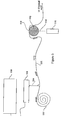
- FIG. 5 is a simplified block diagram of an automated sampling system that utilizes a multiple sample holder, in accordance with an embodiment of the instant invention.
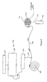
- FIG. 6 is a simplified block diagram of another automated sampling system that utilizes a multiple sample holder, in accordance with an embodiment of the instant invention.
- atmospheric pressure MALDI atmospheric pressure ionization
- other atmospheric pressure ionization techniques particularly laser based techniques such as atmospheric pressure laser desorption chemical ionization (AP/LD/CI)
- AP/LD/CI atmospheric pressure laser desorption chemical ionization
- MALDI atmospheric pressure matrix assisted laser desorption/ ionization
- the laser optionally desorbs the molecule of interest from a surface, a matrix, or a polymer support as some non-limiting examples, and the laser beam may or may not be involved in the ionization process.
- hybrid schemes that include more than one process are used to produce ions.
- ions are produced by laser desorption with ionization using a second laser for multi-photon excitation.
- molecules of a sample are volatilized from a surface followed by gas-phase chemical ionization using a remotely produced reactant ion.
- the instant invention addresses the problem of combining a laser beam and sample holder and a mechanism for desolvating and delivering ions into a FAIMS for ion separation.
- a FAIMS for ion separation.
- the pressure and temperature of the MALDI source and of FAIMS is optionally controllable, and that the operating conditions are selected to obtain a sensitivity and separation as required for the chemical analysis.
- the examples of operating pressures and temperatures in this application are taken for illustrations and should be considered as non-limiting examples.
- FIG. 1 shown is a simplified longitudinal cross sectional view of a system according to an embodiment of the instant invention, including an atmospheric pressure MALDI ion source with a multiple sample holder, and a FAIMS.
- the FAIMS 100 includes a first FAIMS electrode 102 and a second FAIMS electrode 104.
- the first FAIMS electrode 102 and the second FAIMS electrode 104 are disposed in a spaced-apart facing arrangement and define a FAIMS analyzer region 106 therebetween. Ions enter the FARMS analyzer region via an ion inlet orifice 108 that is defined within a portion of the second FAIMS electrode 104.
- a curtain gas region is provided adjacent to the ion inlet orifice 108, to assist in desolvation of ions and to direct neutral molecules away from the ion inlet orifice 108.
- Ions in FAIMS 100 are separated by application of an asymmetric waveform dispersion voltage (DV) and a direct current compensation voltage (CV) by power supply 110, which is in electrical communication with the first FAIMS electrode 102 via an electrical coupling 112 and with the second FAIMS electrode 104 via an electrical coupling 114.
- the voltages applied to the first FAIMS electrode 102 and the second FAIMS electrode 104 create electric fields between these electrodes that separate the ions while the ions are transported by a flow of carrier gas 116 along the analyzer region 106.
- first FAIMS electrode 102 and the second FAIMS electrode 104 are shown as parallel conductive plates, but are optionally micromachined (MEMS) parallel non-curved or curved surfaces, or further optionally, are non-conductive materials that are coated with a conductive layer.
- MEMS micromachined
- each discrete target region 120a, 120b, etc. is fabricated from a material that is opaque, and therefore does not transmit, light at a wavelength of laser light provided from a laser source 122.
- each discrete target region 120a, 120b, etc. is electrically conductive.
- the discrete target regions 120a, 120b, etc. comprise a multiple sample holder 121.
- the multiple sample holder 121 is a 1-row by n-column multiple sample strip.
- a laser beam 124 is projected from the laser light source 122, along an optical path through a laser orifice 126 defined within the first FAIMS electrode 102, through a portion of the analyzer region 106 and outwardly through ion inlet orifice 108 and through a curtain gas orifice 128 defined within a curtain gas plate 130.
- the laser beam 124 impinges upon the sample spots 118a, 118b, etc. and ionizes some of the compounds contained therein.
- curtain gas orifice 128 of curtain plate 130 the laser beam 124 strikes the sample spots 118a, 118b, etc.
- An ion cloud 132 produced by the laser beam impinging upon, for instance, sample spot 118b is directed towards the curtain plate 130 of FAIMS 100 by application of voltages to the multiple sample holder 121 by a not illustrated power supply, and to the curtain plate 130 by power supply 143 via electrical coupling 134.
- a curtain gas flow 136 is provided in the space between the curtain plate 130 and the second FAIMS electrode 104.
- a portion 138 of the curtain gas flow 136 passes outwards through curtain gas orifice 128, and an analyzer gas portion 144 flows into the analyzer region 106 between the first FAIMS electrode 102 and the second FAIMS electrode 104, via the ion inlet orifice 108.
- the portion 138 serves to redirect away from the entrance to FAIMS 100 the neutral molecules that are generated by the laser beam 124 striking the sample spot 118b, for example, and prevents these neutral molecules from entering the space between the curtain plate 130 and the second FAIMS electrode 104.
- the ions 132 are directed towards FAIMS 100 by electric fields generated by voltages applied to the multiple sample holder 121, the curtain plate 130 and the second FAIMS electrode 104.
- each discrete target region 120a, 120b, etc. is at least partly porous or permeable to a flow of a curtain gas 136, such that a portion 138 of the carrier gas 136 is transmitted through the discrete target region 120a, 120b, etc., and therefore carries away neutral molecules generated when a laser beam 124 originating at laser source 122 strikes the sample spot 118a, 118b, etc.
- each discrete target region 120a, 120b, etc. is fabricated from a fine metallic mesh or a fine metal screen that has the desired properties of transparency to the laser beam, electrical conductivity and porosity for passage of the flow 138 of a portion of a carrier gas 136.
- each discrete target region 120a, 120b, etc. of the multiple sample holder 121 is moved into a parallel relationship adjacent to the curtain plate 130 prior to the sample spot 118a, 118b supported thereon being irradiated by the laser beam 124, the ions that are produced are directed in a straight-line trajectory from the discrete target region 120a, 120b, etc. towards the curtain plate 130.
- the ions pass through the curtain gas orifice 128 and are further directed towards ion inlet orifice 108 in the second FAIMS electrode 104 by the electric field between the curtain plate 130 and the second FAIMS electrode 104.
- the multiple sample holder 121 and the curtain plate 130 are sufficiently close together during use to maximize the likelihood of ions produced from the sample spots 118a, 118b, etc. entering the curtain gas orifice 128 of the curtain plate 130.
- a seal 140 is provided for establishing a gas-tight fit between the curtain plate 130 and a solid support portion 142 of the multiple sample holder 121. The distance between the multiple sample holder 121 and the curtain plate 130 is established by optimization of the intensity of signals detected for the ions of interest.
- FIG. 2 shown is a simplified longitudinal cross sectional view of a system according to another embodiment of the instant invention, including an atmospheric pressure MALDI ion source with a multiple sample holder, and a FAIMS.
- the system shown at Figure 2 operates with a modified curtain gas approach for preventing neutrals from entering FAIMS 200.
- the FAIMS 200 includes a first FAIMS electrode 202 and a second FAIMS electrode 204.
- the first FAIMS electrode 202 and the second FAIMS electrode 204 are disposed in a spaced-apart facing arrangement and define a FAIMS analyzer region 206 therebetween.
- Ions enter the FAIMS analyzer region 206 via an ion inlet orifice 208 that is defined within a portion of the second FAIMS electrode 204.
- Ions in FAIMS 200 are separated by application of an asymmetric waveform dispersion voltage (DV) and a direct current compensation voltage (CV) by power supply 210, which is in electrical communication with the first FAIMS electrode 202 via an electrical coupling 212 and with the second FAIMS electrode 204 via an electrical coupling 214.
- DV asymmetric waveform dispersion voltage
- CV direct current compensation voltage
- first FAIMS electrode 202 and the second FAIMS electrode 204 create electric fields between these electrodes that separate the ions while the ions are transported by a flow of carrier gas 216 along the analyzer region 206 from the ion inlet orifice to a not illustrated ion outlet.
- first FAIMS electrode 202 and the second FAIMS electrode 204 are shown as parallel conductive plates, but are optionally micromachined (MEMS) parallel non-curved or curved surfaces, or further optionally are non-conductive materials that are coated with a conductive layer.
- MEMS micromachined
- each discrete target region 220a, 220b, etc. is fabricated from a material that is at least one of partially transmissive and partly transmissive to light at a wavelength of laser light provided from a laser source 222.
- each discrete target region 220a, 220b, etc. is electrically conductive. Furthermore, the each discrete target region 220a, 220b, etc.
- each discrete target region 220a, 220b, etc. is fabricated from a fine metallic mesh or a fine metal screen that has the desired properties of transparency to the laser beam, electrical conductivity and porosity for passage of the flow 244 of a portion of a carrier gas 216 out through the ion inlet orifice 208.
- the discrete target regions 220a, 220b, etc. comprise a multiple sample holder 221.
- the multiple sample holder 221 is a 1-row by n-column multiple sample strip.
- the laser beam 224 is directed to strike a back surface of each discrete target region 220a, 220b, etc., one at a time, while the sample spot 118a, 118b, etc. is supported at the front surface of the respective discrete target region and facing into the analyzer region 206 of FAIMS 200.
- a portion of the laser light is transmitted through the discrete target region 220a, 220b, etc. to the sample spot 218a, 218b, etc., and ionizes some of the compounds contained therein.
- Ions 232 that are produced by the laser beam 224 striking the sample spot, for instance sample spot 218b in Figure 2 are directed into the FAIMS analyzer region 206.
- the ions 232 pass almost immediately into the FAIMS analyzer region 206 via ion inlet orifice 208 without traversing a separate curtain gas region that is external to the FAIMS analyzer region 206.
- those ions that do not posses stable trajectories under the influence of the applied CV and DV are lost rapidly to an electrode surface. Accordingly, the probability of an ion of interest recombining with another ion of opposite polarity is reduced.
- the neutral molecules generated when the laser beam 224 strikes the sample spot, for instance sample spot 118b are prevented from entering the FAIMS analyzer region 206 by the flow of gas 244 outwards through the discrete target region 220b.
- each discrete target region 220a, 220b, etc. of the multiple sample holder 221 is moved into a parallel relationship adjacent to the ion inlet orifice 208 of the second FAIMS electrode 204 prior to the sample spot 218a, 218b supported thereon being irradiated by the laser beam 224, the ions that are produced are directed in an efficient manner from the discrete target region 220a, 220b, etc. towards ion inlet orifice 208.
- the multiple sample holder 221 and the second FAIMS electrode 204 are sufficiently close together during use to maximize the percentage of ions produced from the sample spots 218a, 218b, etc. that enter the ion inlet orifice 208.
- a seal 240 is provided for establishing a gas-tight fit between the second FAIMS electrode 204 and a solid support portion 242 of the multiple sample holder 221.
- the distance between the multiple sample holder 221 and the second FAIMS electrode 204 is established by optimization of the intensity of signals detected for the ions of interest.
- the first FAIMS electrode 202 and the second FAIMS electrode 204 are shown as planar conductive electrodes.
- electrodes according to other FAIMS electrode geometries are used, such as for instance micromachined (MEMS) parallel non-curved or curved surfaces.
- MEMS micromachined
- the electrodes are fabricated from non-conductive materials and are coated with a conductive outer layer.
- Many types of FAIMS geometry may optionally be used, including domed inner electrodes, side-to-side configurations, parallel plates, and spherical geometry, as some non-limiting examples.
- Figure 3a shown is a partial longitudinal cross sectional view of a m-row by n-column multiple sample holder 300 according to an embodiment of the instant invention.
- Figure 3a shows an edge-on view of the multiple sample holder 300, which illustrates that a solid support region 302 is optionally thick relative to discrete target regions 304.
- the dotted lines of discrete target regions 304 denote in Figure 3a a mesh material.
- the discrete target regions 304 are formed of a thin metallic mesh or screen that is at least partly conductive in order to carry electric charges that are generated when a laser beam strikes a not illustrated sample spot supported on one of the discrete target regions 304.
- the mesh or screen does not accumulate sufficient electrostatic charge to create electric fields that adversely affect the formation or transport of ions produced by a pulse of laser radiation striking the sample spot.
- the multiple sample holder 300 is translated to bring each of the discrete target regions 304 into juxtaposition with an ion inlet orifice of the FAIMS system.
- an actuator (not shown) is provided for translating the multiple sample holder relative to the ion inlet, in order to make analytical measurements on each one of a plurality of samples, supported one sample on each discrete target region 304, in rapid succession or in-line with another separation technique.
- the discrete target regions 304 are formed of a material that is also partly transparent to the wavelength of the laser radiation, for supporting irradiation of the sample spot by a laser beam that impinges on a back surface of the discrete target region, as shown for example at Figure 2.
- FIG. 3b shown is a top view of a m-row by n-column multiple sample holder according to an embodiment of the instant invention.
- the number of rows and the number of columns of discrete target regions 304 in the multiple sample holder 300 is not critical.
- the discrete target region 304 is preferably formed of a thin metallic mesh or screen.
- a spot of a sample is applied to a front surface of the discrete target region 304.
- a spot of a sample is applied to a back surface of the discrete target region 304, and the sample material is carried through the mesh or screen material to the front side by capillary action.
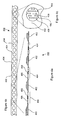
- FIG. 4a shown is a partial longitudinal cross sectional view of a 1-row by n-column multiple sample holder 400 according to an embodiment of the instant invention.
- the multiple sample holder 400 is formed into an elongated strip.
- Figure 4a shows an edge-on view of the multiple sample holder 400, which illustrates that a solid support region 402 is optionally thick relative to discrete target regions 404.
- the dotted lines of discrete target regions 404 denote in Figure 4a a mesh material.
- the discrete target regions 404 are formed of a thin metallic mesh or screen that is at least partly conductive in order to carry electric charges that are generated when a laser beam strikes a not illustrated sample spot supported on one of the discrete target regions 404.
- the mesh or screen does not accumulate sufficient electrostatic charge to create electric fields that adversely affect the formation or transport of ions produced by a pulse of laser radiation striking the sample spot.
- the multiple sample holder 400 is translated to bring each of the discrete target regions 404 into juxtaposition with an ion inlet orifice of the FAIMS system.
- an actuator (not shown) is provided for translating the multiple sample holder 400 relative to the ion inlet, in order to make analytical measurements on each one of a plurality of samples, supported one sample on each discrete target region 404, in rapid succession or in-line with another separation technique.
- the discrete target regions 404 are formed of a material that is also partly transparent to the wavelength of the laser radiation, for supporting irradiation of the sample spot by a laser beam that impinges on a back surface of the discrete target region, as shown for example at Figure 2.
- FIG. 4b shown is a top view of a 1-row by n-column multiple sample strip according to an embodiment of the instant invention.
- the number of columns is not critical.
- FIG. 4c shown is an enlarged top view of one discrete target region 404 of a 1-row by n-column multiple sample strip according to an embodiment of the instant invention.
- Figure 4c shows additional optional features of the discrete target region 404.
- the discrete target region 404 is fabricated optionally from a thin material, preferably a metallic foil, which includes a non-perforated sample deposition region 408 that is surrounded by a region of gas transport holes 406. Each sample is sprayed, or otherwise deposited, on one of the sample deposition regions 408.
- a not illustrated actuator brings each sample deposition region 408 of a discrete target region 404 into the optical path of a laser beam of a not illustrated MALDI laser.
- the neutral molecules of sample and matrix are carried in a direction away from FAIMS by the gas flowing outwards through the gas transport holes 406.
- the sample is deposited on a side of the sample deposition region 408 that faces towards the ion inlet orifice of FAIMS.
- the discrete target regions 404 are formed of a material that is also partly transparent to the wavelength of the laser radiation, for supporting irradiation of the sample spot by a laser beam that impinges on a back surface of the sample deposition region 408 of the discrete target region, as shown for example at Figure 2.
- FIG. 5 shown is a simplified block diagram of an automated sampling system that utilizes a multiple sample holder, in accordance with an embodiment of the instant invention.
- the multiple sample holder is provided in the form of a multiple sample holder strip 500, similar to the multiple sample holder shown at Figure 4b.
- the multiple sample holder strip 500 is held in a coil or similar reservoir 502.
- this sample holder strip 500 is transported past the tip of a sample delivery capillary 504 that is part of a sample applicator 506.
- the control of this sample application, and the reservoirs of individual sample to be applied are housed in the autosampler 508.
- the multiple sample holder strip 500 is translated using a not illustrated actuator to a MALDI ion forming region 510 that is adjacent a not illustrated ion inlet orifice of FAIMS 512. Further detail of the ion forming region 510 is shown at Figure 1. Still referring to Figure 5, after each sample is analyzed in region 510, the multiple sample holder strip 500 is stepwise translated using the actuator, to bring a next discrete target region of the multiple sample holder strip 500 to the ion forming region 510. One or more pulses of laser beam 514 generated by laser source 516 are directed to the sample, and ions are formed by a MALDI and/or gas phase ionization process.
- the ions thereby formed are analyzed in FAIMS 512, and are optionally further analyzed by other FAIMS or detection/analyzers, such as for instance mass spectrometry.
- the laser beam 514 passes through at least one of the electrodes of FAIMS 512, so that the multiple sample holder strip 500 does not have to be transparent to the laser beam.
- the laser source 516 is relocated in such a way that the laser beam 514 strikes the multiple sample holder strip 500 from a side opposite the deposited sample, as is shown in Figure 2.
- FIG. 6 shown is a simplified block diagram of another automated sampling system that utilizes a multiple sample holder, in accordance with an embodiment of the instant invention. Elements labeled with the same numerals have the same function as those illustrated in Figure 5. However, unlike Figure 5 the sample is not provided by an autosampler which is designed to apply discrete types of samples individually on the multiple sample holder strip 500. Instead, the sample is provided from a condensed phase separation system 600. Injector unit 602 injects a portion of a sample into separation system 604 and the components of the sample are separated within the separation system 604. The effluent from such a separation typically contains the components and/or subsets of the components delivered, sequentially in time, out of the outlet capillary 606 of the separation system 604.
- the flowing liquid effluent is then directed through a sampler system 608 that has provision for applying portions of the liquid via a capillary applicator 610 to the multiple sample holder strip 500.
- the multiple sample holder strip 500 optionally includes individual discrete target regions, such as the discrete target regions 404 shown at Figure 4b.
- the multiple sample holder strip 500 supports application of a continuous and non-interrupted flow of sample to the surface of multiple sample holder strip 500.
- a not illustrated actuator is used to continuously pass the multiple sample holder strip 500 through the MALDI laser beam 514, for continuous recording of the components eluted from the condensed phase separations system 600.
- computer programming of the actuator supports automatically slowing down the transport of multiple sample holder strip 500 when few (or no) compounds of interest are being eluted from the condensed phase separation system 600, and increasing the transport speed during delivery of mixtures of interest.
- a portion of a distance that the multiple sample holder strip 500 travels between the capillary applicator 610 and the MALDI ionization region 510 includes a sample dryer for drying or otherwise modifying the samples deposited on the multiple sample holder strip 500.
- a sample material is applied to a sample holder, such that sample material is disposed about first and second points along the sample holder.
- a distance between the first and second points is greater than a maximum dimension of an ion inlet orifice of a FAIMS analyzer.
- the first point is aligned with the ion inlet orifice of the FAIMS analyzer.
- the sample material disposed about the first point is irradiated with laser light of a predetermined wavelength.
- the sample holder is moved relative to the ion inlet so as to align the second point with the ion inlet orifice of the FAIMS analyzer.
- the sample material disposed about the second point is irradiated with laser light of a predetermined wavelength.
Landscapes
- Physics & Mathematics (AREA)
- Chemical & Material Sciences (AREA)
- Analytical Chemistry (AREA)
- Spectroscopy & Molecular Physics (AREA)
- Life Sciences & Earth Sciences (AREA)
- Chemical Kinetics & Catalysis (AREA)
- Electrochemistry (AREA)
- Health & Medical Sciences (AREA)
- Optics & Photonics (AREA)
- Biochemistry (AREA)
- General Health & Medical Sciences (AREA)
- General Physics & Mathematics (AREA)
- Immunology (AREA)
- Pathology (AREA)
- Electron Tubes For Measurement (AREA)
- Other Investigation Or Analysis Of Materials By Electrical Means (AREA)
Applications Claiming Priority (2)
| Application Number | Priority Date | Filing Date | Title |
|---|---|---|---|
| US53788104P | 2004-01-22 | 2004-01-22 | |
| US537881P | 2004-01-22 |
Publications (2)
| Publication Number | Publication Date |
|---|---|
| EP1562042A2 true EP1562042A2 (de) | 2005-08-10 |
| EP1562042A3 EP1562042A3 (de) | 2007-02-21 |
Family
ID=34676903
Family Applications (2)
| Application Number | Title | Priority Date | Filing Date |
|---|---|---|---|
| EP05250304A Withdrawn EP1562042A3 (de) | 2004-01-22 | 2005-01-21 | Verfahren und Gerät für FAIMS zur Reihenanalyse mehrerer Proben |
| EP05250303A Expired - Lifetime EP1574849B1 (de) | 2004-01-22 | 2005-01-21 | Verfahren und Gerät für FAIMS mit laserbasierter Ionisationsquelle |
Family Applications After (1)
| Application Number | Title | Priority Date | Filing Date |
|---|---|---|---|
| EP05250303A Expired - Lifetime EP1574849B1 (de) | 2004-01-22 | 2005-01-21 | Verfahren und Gerät für FAIMS mit laserbasierter Ionisationsquelle |
Country Status (3)
| Country | Link |
|---|---|
| US (2) | US7217921B2 (de) |
| EP (2) | EP1562042A3 (de) |
| CA (2) | CA2493836A1 (de) |
Families Citing this family (27)
| Publication number | Priority date | Publication date | Assignee | Title |
|---|---|---|---|---|
| CA2493836A1 (en) * | 2004-01-22 | 2005-07-22 | Ionalytics Corporation | Method and apparatus for faims for in-line analysis of multiple samples |
| GB0424426D0 (en) | 2004-11-04 | 2004-12-08 | Micromass Ltd | Mass spectrometer |
| US8440968B2 (en) | 2005-02-14 | 2013-05-14 | Micromass Uk Limited | Ion-mobility analyser |
| US20060255261A1 (en) * | 2005-04-04 | 2006-11-16 | Craig Whitehouse | Atmospheric pressure ion source for mass spectrometry |
| US20070272852A1 (en) * | 2006-01-26 | 2007-11-29 | Sionex Corporation | Differential mobility spectrometer analyzer and pre-filter apparatus, methods, and systems |
| US7534997B2 (en) * | 2006-05-25 | 2009-05-19 | Agilent Technologies, Inc. | Mass spectrometer interface for atmospheric ionization ion sources |
| JP4883176B2 (ja) * | 2007-05-09 | 2012-02-22 | 株式会社島津製作所 | 荷電粒子分析装置 |
| US7638765B1 (en) | 2007-07-27 | 2009-12-29 | Thermo Finnigan Llc | FAIMS cell with separate desolvation and carrier gas inlets |
| EP2112683A1 (de) | 2008-04-22 | 2009-10-28 | IEE INTERNATIONAL ELECTRONICS & ENGINEERING S.A. | Differentialmobilitätsspektrometer und Betriebsverfahren dafür |
| JP5579706B2 (ja) * | 2008-05-30 | 2014-08-27 | ディーエイチ テクノロジーズ デベロップメント プライベート リミテッド | 差動移動度分光計用のカーテンガスに調整剤を提供するための方法およびシステム |
| US8049167B2 (en) * | 2009-03-13 | 2011-11-01 | University Of Florida Research Foundation, Inc. | Pneumatic ion beam focusing in high-field asymmetric waveform ion mobility spectrometry (FAIMS) |
| WO2012172330A1 (en) | 2011-06-15 | 2012-12-20 | Malvern Instruments Limited | Surface charge measurement |
| GB201208812D0 (en) | 2012-05-18 | 2012-07-04 | Micromass Ltd | Cryogenic collision cell |
| EP2912676B1 (de) * | 2012-10-28 | 2018-02-21 | PerkinElmer Health Sciences, Inc. | Probenplattformen und verfahren zur verwendung davon |
| US9733156B2 (en) | 2012-10-29 | 2017-08-15 | Perkinelmer Health Sciences, Inc. | Sample platforms and methods of using them |
| WO2014146724A1 (en) * | 2013-03-22 | 2014-09-25 | Eth Zurich | Laser ablation cell |
| SG10201808165YA (en) * | 2013-04-17 | 2018-10-30 | Fluidigm Canada Inc | Sample analysis for mass cytometry |
| GB201317831D0 (en) * | 2013-10-09 | 2013-11-20 | Micromass Ltd | MS/MS analysis using ECD or ETD fragmentation |
| JP6189198B2 (ja) * | 2013-12-06 | 2017-08-30 | 株式会社東芝 | レーザイオン源、イオン加速器及び重粒子線治療装置 |
| CA2850998A1 (en) | 2014-04-18 | 2015-10-18 | Thc Breathalyzer, Inc. | Cannabis drug detection device |
| DE102018112538B3 (de) * | 2018-05-25 | 2019-11-07 | Bruker Daltonik Gmbh | Desorptionsstrahlsteuerung mit virtueller Achsennachführung in Flugzeitmassenspektrometern |
| US10566180B2 (en) | 2018-07-11 | 2020-02-18 | Thermo Finnigan Llc | Adjustable multipole assembly for a mass spectrometer |
| CN111912895A (zh) * | 2019-05-09 | 2020-11-10 | 岛津分析技术研发(上海)有限公司 | 真空下的质谱成像装置及方法 |
| CN110176386B (zh) * | 2019-06-12 | 2020-05-19 | 大连理工大学 | 改进飞行时间质谱测量激光烧蚀离子物种的质谱分辨装置 |
| CN111739786B (zh) * | 2020-07-02 | 2024-02-06 | 中国科学院上海应用物理研究所 | 一种可平动和转动的激光溅射离子源 |
| CN115575483A (zh) * | 2022-09-23 | 2023-01-06 | 安徽医科大学第二附属医院 | 一种直接靶板微滴生长装置及其使用方法 |
| WO2025184325A1 (en) * | 2024-02-28 | 2025-09-04 | Board Of Regents, The University Of Texas System | Particle injectors and methods of use thereof |
Citations (3)
| Publication number | Priority date | Publication date | Assignee | Title |
|---|---|---|---|---|
| US20020005478A1 (en) * | 1996-09-19 | 2002-01-17 | Franz Hillenkamp | Method and apparatus for maldi analysis |
| WO2002084577A1 (en) * | 2001-04-17 | 2002-10-24 | Large Scale Proteomics Corporation | System for optimizing alignment of laser beam with selected points on samples in maldi mass spectrometer |
| WO2003081205A2 (en) * | 2002-03-21 | 2003-10-02 | Thermo Finnigan Llc | Ionization apparatus and method for mass spectrometer system |
Family Cites Families (10)
| Publication number | Priority date | Publication date | Assignee | Title |
|---|---|---|---|---|
| US5420424A (en) * | 1994-04-29 | 1995-05-30 | Mine Safety Appliances Company | Ion mobility spectrometer |
| US5580434A (en) * | 1996-02-29 | 1996-12-03 | Hewlett-Packard Company | Interface apparatus for capillary electrophoresis to a matrix-assisted-laser-desorption-ionization mass spectrometer |
| US6621077B1 (en) * | 1998-08-05 | 2003-09-16 | National Research Council Canada | Apparatus and method for atmospheric pressure-3-dimensional ion trapping |
| US6504149B2 (en) * | 1998-08-05 | 2003-01-07 | National Research Council Canada | Apparatus and method for desolvating and focussing ions for introduction into a mass spectrometer |
| US6690004B2 (en) * | 1999-07-21 | 2004-02-10 | The Charles Stark Draper Laboratory, Inc. | Method and apparatus for electrospray-augmented high field asymmetric ion mobility spectrometry |
| US6495823B1 (en) * | 1999-07-21 | 2002-12-17 | The Charles Stark Draper Laboratory, Inc. | Micromachined field asymmetric ion mobility filter and detection system |
| EP1273029B8 (de) * | 2000-03-14 | 2006-01-11 | National Research Council Canada | Faims apparatur und verfahren mit lasergestützter ionisationsquelle |
| AU2003201232A1 (en) * | 2002-02-08 | 2003-09-02 | Ionalytics Corporation | Faims with non-destructive detection of selectively transmitted ions |
| US7034286B2 (en) * | 2002-02-08 | 2006-04-25 | Ionalytics Corporation | FAIMS apparatus having plural ion inlets and method therefore |
| CA2493836A1 (en) * | 2004-01-22 | 2005-07-22 | Ionalytics Corporation | Method and apparatus for faims for in-line analysis of multiple samples |
-
2005
- 2005-01-21 CA CA002493836A patent/CA2493836A1/en not_active Abandoned
- 2005-01-21 EP EP05250304A patent/EP1562042A3/de not_active Withdrawn
- 2005-01-21 US US11/040,303 patent/US7217921B2/en not_active Expired - Fee Related
- 2005-01-21 US US11/038,144 patent/US7135674B2/en not_active Expired - Fee Related
- 2005-01-21 EP EP05250303A patent/EP1574849B1/de not_active Expired - Lifetime
- 2005-01-21 CA CA002493691A patent/CA2493691A1/en not_active Abandoned
Patent Citations (3)
| Publication number | Priority date | Publication date | Assignee | Title |
|---|---|---|---|---|
| US20020005478A1 (en) * | 1996-09-19 | 2002-01-17 | Franz Hillenkamp | Method and apparatus for maldi analysis |
| WO2002084577A1 (en) * | 2001-04-17 | 2002-10-24 | Large Scale Proteomics Corporation | System for optimizing alignment of laser beam with selected points on samples in maldi mass spectrometer |
| WO2003081205A2 (en) * | 2002-03-21 | 2003-10-02 | Thermo Finnigan Llc | Ionization apparatus and method for mass spectrometer system |
Also Published As
| Publication number | Publication date |
|---|---|
| EP1562042A3 (de) | 2007-02-21 |
| EP1574849B1 (de) | 2012-09-26 |
| EP1574849A3 (de) | 2007-03-07 |
| CA2493836A1 (en) | 2005-07-22 |
| US7135674B2 (en) | 2006-11-14 |
| CA2493691A1 (en) | 2005-07-22 |
| EP1574849A2 (de) | 2005-09-14 |
| US20050161598A1 (en) | 2005-07-28 |
| US20050161597A1 (en) | 2005-07-28 |
| US7217921B2 (en) | 2007-05-15 |
Similar Documents
| Publication | Publication Date | Title |
|---|---|---|
| US7217921B2 (en) | Method and apparatus for FAIMS for in-line analysis of multiple samples | |
| US9523657B2 (en) | Practical ion mobility spectrometer apparatus and methods for chemical and/or biological detection | |
| Huang et al. | Ambient ionization mass spectrometry | |
| US7928364B2 (en) | Sampling system for containment and transfer of ions into a spectroscopy system | |
| US8440965B2 (en) | Sampling system for use with surface ionization spectroscopy | |
| Li et al. | On‐demand ambient ionization of picoliter samples using charge pulses | |
| US20080067348A1 (en) | High resolution sampling system for use with surface ionization technology | |
| US20210270773A1 (en) | Structural analysis of ionised molecules | |
| KR20050032034A (ko) | 생체 분자 또는 기타 분자 어레이의 제조를 위한 시스템및 방법 | |
| US10794862B2 (en) | Practical ion mobility spectrometer apparatus and methods for chemical and/or biological detection | |
| KR102314968B1 (ko) | 최적화된 표적 분석 | |
| US10309929B2 (en) | Practical ion mobility spectrometer apparatus and methods for chemical and/or biological detection | |
| JP2021524665A (ja) | イオン化源ならびにそれを使用するシステム及び方法 | |
| US10073056B2 (en) | Practical ion mobility spectrometer apparatus and methods for chemical and/or biological detection | |
| Kennedy et al. | Evaluation and performance of desorption electrospray ionization using a triple quadrupole mass spectrometer for quantitation of pharmaceuticals in plasma | |
| Mallet et al. | Dictionary of mass spectrometry | |
| US7473893B2 (en) | ICP/ESI mass spectrometry systems and methods of use thereof | |
| Campbell et al. | Increased ion transmission for differential ion mobility combined with mass spectrometry by implementation of a flared inlet capillary | |
| Yang et al. | Preparative separation of a multicomponent peptide mixture by mass spectrometry | |
| US11328917B2 (en) | MALDI target plate | |
| US11460440B2 (en) | Practical ion mobility spectrometer apparatus and methods for chemical and/or biological detection | |
| Navare et al. | Inline pneumatically assisted atmospheric pressure matrix‐assisted laser desorption/ionization ion trap mass spectrometry | |
| Pröfrock | Coupling techniques and orthogonal combination of mass spectrometric techniques | |
| US20200395204A1 (en) | Ionization sources and methods and systems using them | |
| Smith | An evaluation of miniaturised field asymmetric waveform ion mobility spectrometry hyphenated with time-of-flight mass spectrometry |
Legal Events
| Date | Code | Title | Description |
|---|---|---|---|
| PUAI | Public reference made under article 153(3) epc to a published international application that has entered the european phase |
Free format text: ORIGINAL CODE: 0009012 |
|
| AK | Designated contracting states |
Kind code of ref document: A2 Designated state(s): AT BE BG CH CY CZ DE DK EE ES FI FR GB GR HU IE IS IT LI LT LU MC NL PL PT RO SE SI SK TR |
|
| AX | Request for extension of the european patent |
Extension state: AL BA HR LV MK YU |
|
| PUAL | Search report despatched |
Free format text: ORIGINAL CODE: 0009013 |
|
| AK | Designated contracting states |
Kind code of ref document: A3 Designated state(s): AT BE BG CH CY CZ DE DK EE ES FI FR GB GR HU IE IS IT LI LT LU MC NL PL PT RO SE SI SK TR |
|
| AX | Request for extension of the european patent |
Extension state: AL BA HR LV MK YU |
|
| RIC1 | Information provided on ipc code assigned before grant |
Ipc: H01J 49/42 20060101ALI20070116BHEP Ipc: G01N 27/64 20060101AFI20050616BHEP |
|
| RAP1 | Party data changed (applicant data changed or rights of an application transferred) |
Owner name: THERMO FINNIGAN LLC |
|
| 17P | Request for examination filed |
Effective date: 20070813 |
|
| 17Q | First examination report despatched |
Effective date: 20070925 |
|
| AKX | Designation fees paid |
Designated state(s): DE GB |
|
| STAA | Information on the status of an ep patent application or granted ep patent |
Free format text: STATUS: THE APPLICATION IS DEEMED TO BE WITHDRAWN |
|
| 18D | Application deemed to be withdrawn |
Effective date: 20120608 |