EP1562043A1 - Verfahren und Vorrichtung zur Feststellung der lateralen Lage einer Kante eines Geweber oder einer Warenbahn - Google Patents
Verfahren und Vorrichtung zur Feststellung der lateralen Lage einer Kante eines Geweber oder einer Warenbahn Download PDFInfo
- Publication number
- EP1562043A1 EP1562043A1 EP05397004A EP05397004A EP1562043A1 EP 1562043 A1 EP1562043 A1 EP 1562043A1 EP 05397004 A EP05397004 A EP 05397004A EP 05397004 A EP05397004 A EP 05397004A EP 1562043 A1 EP1562043 A1 EP 1562043A1
- Authority
- EP
- European Patent Office
- Prior art keywords
- fabric
- web
- ultrasonic sensor
- ultrasonic
- edge
- Prior art date
- Legal status (The legal status is an assumption and is not a legal conclusion. Google has not performed a legal analysis and makes no representation as to the accuracy of the status listed.)
- Granted
Links
- 239000004744 fabric Substances 0.000 title claims abstract description 93
- 238000000034 method Methods 0.000 title claims abstract description 21
- 238000005259 measurement Methods 0.000 claims abstract description 13
- 238000002604 ultrasonography Methods 0.000 claims abstract description 10
- 230000001681 protective effect Effects 0.000 claims description 24
- 238000001816 cooling Methods 0.000 claims description 7
- 238000001514 detection method Methods 0.000 claims description 2
- 230000003287 optical effect Effects 0.000 description 9
- 238000012546 transfer Methods 0.000 description 6
- 238000013461 design Methods 0.000 description 5
- 238000010276 construction Methods 0.000 description 4
- 230000000694 effects Effects 0.000 description 4
- 238000004140 cleaning Methods 0.000 description 3
- 238000012544 monitoring process Methods 0.000 description 3
- 238000010420 art technique Methods 0.000 description 2
- 238000001035 drying Methods 0.000 description 2
- 238000004519 manufacturing process Methods 0.000 description 2
- 238000012545 processing Methods 0.000 description 2
- 238000009825 accumulation Methods 0.000 description 1
- 230000003467 diminishing effect Effects 0.000 description 1
- 230000002349 favourable effect Effects 0.000 description 1
- 239000012535 impurity Substances 0.000 description 1
- 238000009434 installation Methods 0.000 description 1
- 238000009413 insulation Methods 0.000 description 1
- 230000007257 malfunction Effects 0.000 description 1
- 239000000463 material Substances 0.000 description 1
- NJPPVKZQTLUDBO-UHFFFAOYSA-N novaluron Chemical compound C1=C(Cl)C(OC(F)(F)C(OC(F)(F)F)F)=CC=C1NC(=O)NC(=O)C1=C(F)C=CC=C1F NJPPVKZQTLUDBO-UHFFFAOYSA-N 0.000 description 1
- 230000002028 premature Effects 0.000 description 1
- 239000002689 soil Substances 0.000 description 1
- 229910001220 stainless steel Inorganic materials 0.000 description 1
- 239000010935 stainless steel Substances 0.000 description 1
- 238000012360 testing method Methods 0.000 description 1
Images


Classifications
-
- G—PHYSICS
- G01—MEASURING; TESTING
- G01N—INVESTIGATING OR ANALYSING MATERIALS BY DETERMINING THEIR CHEMICAL OR PHYSICAL PROPERTIES
- G01N29/00—Investigating or analysing materials by the use of ultrasonic, sonic or infrasonic waves; Visualisation of the interior of objects by transmitting ultrasonic or sonic waves through the object
- G01N29/22—Details, e.g. general constructional or apparatus details
- G01N29/26—Arrangements for orientation or scanning by relative movement of the head and the sensor
- G01N29/27—Arrangements for orientation or scanning by relative movement of the head and the sensor by moving the material relative to a stationary sensor
-
- B—PERFORMING OPERATIONS; TRANSPORTING
- B65—CONVEYING; PACKING; STORING; HANDLING THIN OR FILAMENTARY MATERIAL
- B65H—HANDLING THIN OR FILAMENTARY MATERIAL, e.g. SHEETS, WEBS, CABLES
- B65H23/00—Registering, tensioning, smoothing or guiding webs
- B65H23/02—Registering, tensioning, smoothing or guiding webs transversely
- B65H23/0204—Sensing transverse register of web
-
- D—TEXTILES; PAPER
- D21—PAPER-MAKING; PRODUCTION OF CELLULOSE
- D21F—PAPER-MAKING MACHINES; METHODS OF PRODUCING PAPER THEREON
- D21F1/00—Wet end of machines for making continuous webs of paper
- D21F1/36—Guiding mechanisms
- D21F1/365—Guiding mechanisms for controlling the lateral position of the screen
-
- G—PHYSICS
- G01—MEASURING; TESTING
- G01B—MEASURING LENGTH, THICKNESS OR SIMILAR LINEAR DIMENSIONS; MEASURING ANGLES; MEASURING AREAS; MEASURING IRREGULARITIES OF SURFACES OR CONTOURS
- G01B17/00—Measuring arrangements characterised by the use of infrasonic, sonic or ultrasonic vibrations
-
- G—PHYSICS
- G01—MEASURING; TESTING
- G01N—INVESTIGATING OR ANALYSING MATERIALS BY DETERMINING THEIR CHEMICAL OR PHYSICAL PROPERTIES
- G01N29/00—Investigating or analysing materials by the use of ultrasonic, sonic or infrasonic waves; Visualisation of the interior of objects by transmitting ultrasonic or sonic waves through the object
- G01N29/04—Analysing solids
- G01N29/041—Analysing solids on the surface of the material, e.g. using Lamb, Rayleigh or shear waves
-
- B—PERFORMING OPERATIONS; TRANSPORTING
- B65—CONVEYING; PACKING; STORING; HANDLING THIN OR FILAMENTARY MATERIAL
- B65H—HANDLING THIN OR FILAMENTARY MATERIAL, e.g. SHEETS, WEBS, CABLES
- B65H2553/00—Sensing or detecting means
- B65H2553/30—Sensing or detecting means using acoustic or ultrasonic elements
-
- G—PHYSICS
- G01—MEASURING; TESTING
- G01N—INVESTIGATING OR ANALYSING MATERIALS BY DETERMINING THEIR CHEMICAL OR PHYSICAL PROPERTIES
- G01N2291/00—Indexing codes associated with group G01N29/00
- G01N2291/02—Indexing codes associated with the analysed material
- G01N2291/023—Solids
- G01N2291/0237—Thin materials, e.g. paper, membranes, thin films
-
- G—PHYSICS
- G01—MEASURING; TESTING
- G01N—INVESTIGATING OR ANALYSING MATERIALS BY DETERMINING THEIR CHEMICAL OR PHYSICAL PROPERTIES
- G01N2291/00—Indexing codes associated with group G01N29/00
- G01N2291/02—Indexing codes associated with the analysed material
- G01N2291/028—Material parameters
- G01N2291/02854—Length, thickness
-
- G—PHYSICS
- G01—MEASURING; TESTING
- G01N—INVESTIGATING OR ANALYSING MATERIALS BY DETERMINING THEIR CHEMICAL OR PHYSICAL PROPERTIES
- G01N2291/00—Indexing codes associated with group G01N29/00
- G01N2291/04—Wave modes and trajectories
- G01N2291/057—Angular incidence, parallel to surface propagation
-
- G—PHYSICS
- G01—MEASURING; TESTING
- G01S—RADIO DIRECTION-FINDING; RADIO NAVIGATION; DETERMINING DISTANCE OR VELOCITY BY USE OF RADIO WAVES; LOCATING OR PRESENCE-DETECTING BY USE OF THE REFLECTION OR RERADIATION OF RADIO WAVES; ANALOGOUS ARRANGEMENTS USING OTHER WAVES
- G01S15/00—Systems using the reflection or reradiation of acoustic waves, e.g. sonar systems
- G01S15/88—Sonar systems specially adapted for specific applications
Definitions
- the invention relates to a method for determining the lateral position of a web or fabric edge in a web forming machine, the method utilizing ultrasound.
- the invention also relates to a corresponding apparatus.
- US patent No. 5834877 describes an ultrasonic sensor for determining the web edge position, the sensor comprising a U-shape housing.
- the upper branch of the sensor housing accommodates an ultrasonic transmitter and the lower branch an ultrasonic receiver.
- the ultrasonic sensor is placed near the web such that the web travels through the gap between the branches.
- the power received by the ultrasonic receiver varies, based on which the ultrasonic sensor controller determines the edge position relative to the sensor housing.
- the proposed ultrasonic sensor must be positioned very near to the edge, which makes it vulnerable to damage.
- the web must remain accurately in place in the vertical direction, which reduces the positioning options of the sensor housing. Due to its construction and position, the sensor housing also soils easily, and its cleaning is difficult.
- the proposed ultrasonic sensor cannot be located in humid or hot conditions, which are common in a web producing machine manufacturing web.
- optical sensors which are based on a photoelectric trip device, are today used in web forming machines.
- the reflection of light directed to the fabric is detected by adjacent receivers, based on which the position of the edge can be determined. This position information is then used for example for guiding and holding the fabric in a desired position in the cross direction of a paper machine.
- the accuracy of optical sensors is often insufficient.
- web moisture or fabric impurities affect the performance of optical sensors, which complicates the control of the apparatus and causes errors.
- using optical sensors at the so-called wet end of a web forming machine is impossible.
- Optical sensors must also be positioned near the web or fabric, which leads to their soiling and even to damaging.
- DE patent No. 3913601 sets forth determination of a sieve belt edge using ultrasonic measurement.
- a sieve belt is narrow and its thickness is several tens of millimeters.
- the speed of a sieve belt is notably lower than that of a web or fabric of a web forming machine.
- the measuring head included in the apparatus must be located disadvantageously close to the sieve belt.
- the positioning of the sieve belt is very restricted and its application in hot and humid conditions is impossible.
- the object of the invention is to provide a new method for determining the lateral position of a web or fabric edge in a web forming machine, the method being simpler, yet more versatile than heretofore, and avoiding the disadvantages of the prior art technique.
- Another object of the invention is to provide a new apparatus for determining the lateral position of a web or fabric edge in a web forming machine, which apparatus can be positioned in a web forming machine more easily and freely than heretofore and has a simpler and more protected design than heretofore.
- the features characterizing this method in accordance with the invention become evident from the appended claim 1. Likewise, the features characterizing the apparatus according to the invention become evident from the appended claim 6.
- the method according to the invention uses ultrasound in a new and surprising way.
- the position of the web or fabric edge can be easily and accurately determined.
- the design of the apparatus remains simple and the ultrasonic sensor can be located in a protected position.
- suitable auxiliary means it is also possible to prevent the ultrasonic sensor from soiling and damaging. Simultaneously, uninterrupted operation of the apparatus can be ensured even in very demanding conditions.
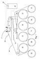
- Figure 1 depicts a fabric guide known in the art arranged in connection with a roll 17 supporting the fabric 10 of a web forming machine.
- the term 'web forming machine' is used here to refer mainly to a paper or board machine.
- the fabric guide is arranged to guide a dryer fabric serving as the fabric 10, which travels as an endless loop via drying cylinders 12, vacuum cylinders 13 and lead rolls 14 - 18.
- the apparatus can be used to guide a press felt, for example, or some other fabric used in a paper machine.
- the fabric guide known in the art has two sensor elements for determining the fabric edge position in the cross direction of the web forming machine. Each sensor element has a plurality of optical sensors.
- edge position information for fabric guiding, it is additionally required to have a measuring card 24 located in a protected equipment cabinet 25. Based on the information collected from the optical sensors it is then possible to determine the position of the fabric edge and thus control the fabric guide.
- the data transfer channels between the sensor elements, measuring card and fabric guide are represented with dot-and-dash lines in Figure 1.
- FIGs 2a and 2b show a more detailed illustration of the fabric guide known in the art, comprising a base 19 adapted to be fastened to the web forming machine frame, and a transfer base 20 movably adapted to the base 19.
- Fabric guiding is provided by changing the position of the roll 17.
- the bearing pedestal 21 of the roll 17 is fastened to the transfer base 20, which thus moves in the machine direction.
- the bearing assembly of the roll allows this movement, which can be as long as 100 mm. In practice, however, a movement of a few millimeters is sufficient for providing the desired guiding effect.
- the transfer base 20 is movably fastened to the base 19 by means of linear guides (not shown).
- the fabric guide known in the prior art technique comprises the above mentioned sensor elements 23, which are used for determining the position of the fabric 10 in the axial direction of the roll 17.
- an electronic system connected to the fabric guide continuously compares the measuring results of the optical sensors with the set values and, if necessary, moves the transfer base over the required distance by controlling the motor.
- the method according to the invention uses ultrasound.
- the edge position is surprisingly determined by means of a distance measurement.
- the distance is measured at the sides of the web or fabric. This allows positioning the measuring equipment far from the web or fabric, reducing in this way their soiling. Furthermore, there is more freedom in the positioning of the equipment, and the equipment is smaller and simpler in design than heretofore.
- the distance is measured with ultrasound in the lateral direction outside the web or fabric.
- Figure 2b shows an apparatus according to the invention arranged in connection with a known fabric guide, the apparatus comprising an ultrasonic sensor 26. According to the invention, the ultrasonic sensor can be positioned substantially far from the fabric.
- the ultrasonic sensor 26 can be located more freely than heretofore in various positions of the fabric.
- Two preferable locating positions of the ultrasonic sensor 26 are shown in Figure 1 with a dimmed circle.
- the ultrasonic sensor can be located in a different position, such as the pocket between the drying cylinders 12 and vacuum cylinder 13 (circle drawn with dash line).
- a preferable installation position for the sensor is near the roll that guides the fabric, in which case it is possible to achieve a control feedback with almost no delay.
- the guide roll can additionally have integrated fabric stretching or felt squaring or even all these three functions.
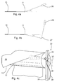
- Figures 4a and 4b show a principal drawing of the ultrasonic sensor 26 located in connection with the fabric 10.
- the distance measurement is so arranged that between the ultrasonic propagation direction and the plane formed by the web or fabric there is formed an angle ⁇ that is smaller than the right angle.
- the ultrasonic sensor 26 is arranged above or below the plane formed by the web or fabric 10. The distance is thus measured only at one point.
- the angle ⁇ is adapted to size 0° - 50°, more preferably 0° - 10°.
- the effect of reflection of the web or fabric is reduced by diminishing the angle.
- a measurement made as much as possible from the side is the most accurate in practice.
- the positioning of the ultrasonic sensor in the web forming machine is easy.
- the ultrasonic sensor is directed towards the edge 11 of the fabric 10, but the ultrasonic propagation direction can also be changed in the distance measurement by reflecting at least once.
- Figure 4b in which there is arranged a suitable reflector 27 between the ultrasonic sensor 26 and the edge 11 of the fabric 10.
- the reflection axis of the reflector is horizontal, but by using a vertical reflection axis the ultrasonic sensor can be positioned for example behind the frame beam of the web forming machine for protection (not shown). If required, the ultrasonic propagation direction can be changed by reflecting even twice.
- the ultrasonic sensor is thus located to the side of the web or fabric.
- the ultrasonic sensor is adapted to measure the distance between the ultrasonic sensor and the edge for determining the position of the edge.
- determining the edge position is more accurate and easier than heretofore.
- the apparatus can as well be used for determining the edge of a web or a paper web. In total, the design of the apparatus remains simple, when using the ultrasonic sensor 26, which comprises an ultrasonic transmitter 28 and an ultrasonic receiver 29 adapted in one sensor housing 30 ( Figure 3a).
- the sensor housing accommodates measuring electronics 31 for processing the information produced by the ultrasonic transmitter 28 and the ultrasonic receiver 29.
- the measuring electronics directly provides an analogic voltage or current message, which can be used as such for controlling a fabric guide, for example.
- the principle of an ultrasonic sensor 26 according to the invention is shown in Figure 3a with dash lines.
- the connection cable 32 leading directly from the ultrasonic sensor 26 to the fabric guide is shown with dash lines in Figures 1, 2a and 2b.
- the apparatus comprises support elements 33 for locating the ultrasonic sensor preferably at a suitably defined safety distance from the edge 11.
- the distance can be for example 100 mm, although the ultrasonic sensor itself does not require limiting of the closest measuring distance.
- a suitable locating distance is approximately 400 - 1500 mm, more preferably 501 - 750 mm, in which case the ultrasonic sensor can be fastened to the frame constructions of the web forming machine or even outside them.
- the support elements 33 comprise a support arm 34 and a protective cover 35 adapted thereto for the sensor housing. In practice, the support arm is fastened to the above mentioned frame constructions, for example.
- the protective cover is essential in particular as regards the performance of the ultrasonic sensor.
- air is conducted into the protective cover, which, besides providing cooling, keeps the ultrasonic sensor clean.
- Figure 2b shows the principle of the compressed air source 37. In favorable conditions cooling may be unnecessary, in which case normal compressed air, for example, is used.
- a vortex pipe may be connected to the protective cover for providing a cooling air flow inside the protective cover. This is shown in Figure 4c, in which the vortex pipe 38 with compressed air connections 39 is fastened to the protective cover 35.
- the protective cover is a casing made of stainless steel pipe that can be opened at the center.
- the ultrasonic sensor itself is screwed to the threading arranged at the end wall of the casing.
- the thread is in the nut 40 fastened to the end of the protective cover 35.
- the ultrasonic sensor is thus fastened to the protective cover only at its end part, allowing the cooling air to efficiently surround particularly the electronic components (Figure 3a).
- the ultrasonic sensor also comprises a detector head 42, which is the only part in connection with the surrounding air.
- the detector head also has a specific layer, which transmits ultrasonic waves between the detector head and the external air preventing at the same time conduction of heat into the protective cover.
- the channel system opens to the vicinity of the detector head for forming an air knife.
- the air knife prevents accumulation of dirt in the detector head.
- the proposed protective cover 35 has an air guide 43 extending further than the detector head 42, with air flowing thereabove from inside the protective cover 35 through an opening 36.
- the air guide 36 is shown in Figure 3b.
- the protective cover 35 is completed with an end component 44 having a detent 45 designed according to the air guide 36.
- the end component is on top of the protective cover allowing air to flow from the opening between the air guide and the end component to the detent, which turns the direction of the air flow (Figure 3a).
- This provides efficient cleaning without disturbing, however, the operation of the ultrasonic sensor.
- the air knife is arranged essentially in the cross direction relative to the ultrasonic propagation direction, preventing thus temperature variations within the measuring range. Air flows are represented with arrows in Figures 3a and 3b.
- piezoceramic components function as a transmitter and receiver.
- the detection head has an acoustically thin medium layer through which ultrasound is transmitted to the surrounding air and vice versa. This provides good accuracy for the ultrasonic sensor allowing it to be used even in demanding conditions.
- the sensor housing itself is watertight.
- compressed air generates an overpressure, which prevents access of moisture to the sensor housing.
- the ultrasonic sensor transmits a package of sound pulses and converts the received echo pulses directly into voltage or current messages by means of its measuring electronics.
- the measuring electronics integrated in the ultrasonic sensor determines the distance based mainly on the echo time and speed of sound.
- the frequency of ultrasound is approximately 65 - 400 kHz depending on the sensor type.
- the iterative frequency of the sound pulse is approximately 14 - 140 Hz.
- the ultrasonic sensor forms a sound cone with a cone angle of 10° in the tested apparatus.
- the sound cone opens outwardly from the ultrasonic sensor and generally the object is detected, if it is in the range of the sound cone or moves across the sound cone.
- the principle of the sound cone is shown in Figures 2b and 4c with dot-and-dash lines.
- the measuring accuracy of the ultrasonic sensor can be improved, and malfunctions can be minimized by setting with the measuring electronics a certain measuring range, whose echo pulses only are detected by the ultrasonic sensor.
- the measuring range of the apparatus according to the invention is multi-tenfold compared to conventional apparatuses.
- the ultrasonic sensor can be set as a relay or connected to a computer or other logic system, for example, by means of serial connection. Serial connection also enables changing the settings of the ultrasonic sensor and using versatile measuring functions.
- the ultrasonic sensor has preferably also a temperature sensor based on which the measuring electronics compensates the effect of the temperature on the operation of the apparatus. In this case, irrespective of changes in conditions, the accuracy and reliability of the apparatus remain unchanged. Suitable for use in the apparatus are particularly the ultrasonic precision sensors.
- the method and apparatus according to the invention are particularly suitable for large and high-speed web forming machines, in which the width of the web or fabric exceeds 5 meters, most commonly 8 - 11 meters, in the future as much as 15 meters.
- the fabrics' price per width meter also increases. That is, wide fabrics are proportionally more expensive than narrow fabrics.
- devices touching the fabric edge for determining the fabric position should be avoided.
- the price of such devices is affordable, their use reduces the fabric life.
- the life of which is several months, even several tens of months a touching edge sensor can rub the fabric edge such that it becomes weaker than the rest of the fabric.
- the ultrasonic sensor there is more freedom than heretofore for the positioning of the ultrasonic sensor.
- a preferable position for an ultrasonic sensor measuring the fabric from the side is between the frame constructions.
- the ultrasonic sensor is protected, besides by its protective cover, for example against an impact by an off-tracked damaged fabric.
- less material is accumulated compared to sensor applications that are positioned near the fabric. This reduces the cleaning frequency of the ultrasonic sensor.
- the ultrasonic sensor is insensitive to minor soiling, which can also be avoided by using an air knife according to the invention.
- the apparatus according to the invention functions also with thin webs and fabrics having a thickness of as small as below 5 mm.
- dryer fabrics are used, among others, having a thickness of approximately 1 - 2 mm.
- wet fabrics are approximately 0.4 - 2 mm thick.
- the apparatus can additionally be used also for press felts and belts, the thickness of which is usually approximately 2 - 4 mm.
- the previously mentioned protective cover is preferably used, which at the same time serves as thermal insulation also cooling the ultrasonic sensor.
- only a moisture-insulating protective cover can be used or the ultrasonic sensor can be located even without a protective cover.
- the method according to the invention can be used in various web forming machines for monitoring the edge of various webs and fabrics. In addition to fabrics, the method can also be used for example for monitoring and measuring the web and its width as well as for break monitoring. A lateral distance measurement provides an accurate position determination in a simple manner.
- the apparatus according to the invention can be freely located in various positions in the web forming machine including humid and hot conditions. In practice, the design of the apparatus is simple and the edge position information provided by it can be directly used for controlling other apparatuses, for example.
Landscapes
- Physics & Mathematics (AREA)
- General Physics & Mathematics (AREA)
- General Health & Medical Sciences (AREA)
- Immunology (AREA)
- Life Sciences & Earth Sciences (AREA)
- Chemical & Material Sciences (AREA)
- Analytical Chemistry (AREA)
- Biochemistry (AREA)
- Pathology (AREA)
- Health & Medical Sciences (AREA)
- Acoustics & Sound (AREA)
- Treatment Of Fiber Materials (AREA)
- Length Measuring Devices Characterised By Use Of Acoustic Means (AREA)
- Controlling Rewinding, Feeding, Winding, Or Abnormalities Of Webs (AREA)
- Length Measuring Devices By Optical Means (AREA)
- Investigating Or Analyzing Materials By The Use Of Ultrasonic Waves (AREA)
- Paper (AREA)
Applications Claiming Priority (2)
| Application Number | Priority Date | Filing Date | Title |
|---|---|---|---|
| FI20045028A FI118274B (fi) | 2004-02-05 | 2004-02-05 | Menetelmä ja laitteisto rainan tai kudoksen reunan sivuttaissuuntaisen sijainnin määrittämiseksi rainanmuodostuskoneessa |
| FI20045028 | 2004-02-05 |
Publications (2)
| Publication Number | Publication Date |
|---|---|
| EP1562043A1 true EP1562043A1 (de) | 2005-08-10 |
| EP1562043B1 EP1562043B1 (de) | 2012-03-14 |
Family
ID=31725795
Family Applications (1)
| Application Number | Title | Priority Date | Filing Date |
|---|---|---|---|
| EP05397004A Expired - Lifetime EP1562043B1 (de) | 2004-02-05 | 2005-01-26 | Verfahren und Vorrichtung zur Feststellung der lateralen Lage einer Kante eines Gewebes oder einer Warenbahn |
Country Status (4)
| Country | Link |
|---|---|
| US (1) | US7390379B2 (de) |
| EP (1) | EP1562043B1 (de) |
| AT (1) | ATE549618T1 (de) |
| FI (1) | FI118274B (de) |
Cited By (1)
| Publication number | Priority date | Publication date | Assignee | Title |
|---|---|---|---|---|
| WO2007147572A1 (de) | 2006-06-22 | 2007-12-27 | Betriebsforschungsinstitut VDEh-Institut für angewandte Forschung GmbH | Verfahren und vorrichtung zur bestimmung der bandkantenlage und/oder der zugspannungsverteilung über die bandbreite eines bandes |
Families Citing this family (6)
| Publication number | Priority date | Publication date | Assignee | Title |
|---|---|---|---|---|
| FR2960413B1 (fr) * | 2010-05-25 | 2013-03-22 | Essilor Int | Dispositif de mesure d'une distance caracteristique de lecture d'un individu |
| DE202011002054U1 (de) | 2011-01-28 | 2011-05-26 | Texmag Gmbh Vertriebsgesellschaft | Ultraschall-Kantensensor |
| FI126286B (fi) * | 2012-02-14 | 2016-09-15 | Valmet Technologies Inc | Järjestelmä sähkölaitteen jäähdyttämiseksi kuiturainakoneessa |
| KR20150074050A (ko) | 2012-10-25 | 2015-07-01 | 그라코 미네소타 인크. | 핫 멜트 수준 센서 및 센서 하우징 |
| JP7081143B2 (ja) * | 2017-12-27 | 2022-06-07 | セイコーエプソン株式会社 | 超音波装置、及び超音波測定方法 |
| DE102021126548A1 (de) * | 2021-10-13 | 2023-04-13 | Maschinenfabrik Rieter Ag | Verfahren zum Positionieren einer verfahrbaren Wartungseinrichtung an einer Textilmaschine sowie Textilmaschine |
Citations (5)
| Publication number | Priority date | Publication date | Assignee | Title |
|---|---|---|---|---|
| DE3913601A1 (de) | 1989-04-25 | 1990-10-31 | Dornier Gmbh Lindauer | Bandsteuerung fuer einen siebbandtrockner |
| US5488867A (en) | 1992-08-21 | 1996-02-06 | Xecutek Corporation | Strip measuring and centering system |
| EP0740154A1 (de) * | 1995-04-28 | 1996-10-30 | Kodak Limited | Detektor für Folienmaterial |
| DE19852719A1 (de) * | 1997-12-10 | 1999-06-17 | Heidelberger Druckmasch Ag | Doppelbogen-Erkennungsvorrichtung |
| US20020014120A1 (en) * | 2000-06-21 | 2002-02-07 | Bernd Wunderer | Method for determining structural inhomogeneities in sheet material |
Family Cites Families (6)
| Publication number | Priority date | Publication date | Assignee | Title |
|---|---|---|---|---|
| DE2540923B2 (de) * | 1975-09-13 | 1978-01-12 | EMA-Dörries GmbH, Elektronik-Maschinen-Apparatebau, 5190 Stolberg | Vorrichtung zur regelung der spannung eines endlosen filzes oder siebes in papiermaschinen |
| DE3442154A1 (de) * | 1984-11-17 | 1986-05-28 | Elektro-Mechanik Gmbh, 5963 Wenden | Verfahren zur positionserfassung der bandkante einer materialbahn |
| DE3815205C2 (de) * | 1987-05-08 | 1995-06-29 | Hitachi Construction Machinery | Verstärkerschaltung mit regelbarem Verstärkungsfaktor |
| US4914641A (en) * | 1988-11-10 | 1990-04-03 | Xecutek Corporation | Ultrasonic measuring device and method |
| US5565627A (en) * | 1994-10-11 | 1996-10-15 | Xecutek Corporation | Ultrasonic edge detector and control system |
| WO1997008761A1 (en) * | 1995-08-28 | 1997-03-06 | Accuweb, Inc. | Ultrasonic transducer units for web edge detection |
-
2004
- 2004-02-05 FI FI20045028A patent/FI118274B/fi active IP Right Grant
-
2005
- 2005-01-26 EP EP05397004A patent/EP1562043B1/de not_active Expired - Lifetime
- 2005-01-26 AT AT05397004T patent/ATE549618T1/de active
- 2005-02-04 US US11/051,847 patent/US7390379B2/en active Active
Patent Citations (5)
| Publication number | Priority date | Publication date | Assignee | Title |
|---|---|---|---|---|
| DE3913601A1 (de) | 1989-04-25 | 1990-10-31 | Dornier Gmbh Lindauer | Bandsteuerung fuer einen siebbandtrockner |
| US5488867A (en) | 1992-08-21 | 1996-02-06 | Xecutek Corporation | Strip measuring and centering system |
| EP0740154A1 (de) * | 1995-04-28 | 1996-10-30 | Kodak Limited | Detektor für Folienmaterial |
| DE19852719A1 (de) * | 1997-12-10 | 1999-06-17 | Heidelberger Druckmasch Ag | Doppelbogen-Erkennungsvorrichtung |
| US20020014120A1 (en) * | 2000-06-21 | 2002-02-07 | Bernd Wunderer | Method for determining structural inhomogeneities in sheet material |
Cited By (1)
| Publication number | Priority date | Publication date | Assignee | Title |
|---|---|---|---|---|
| WO2007147572A1 (de) | 2006-06-22 | 2007-12-27 | Betriebsforschungsinstitut VDEh-Institut für angewandte Forschung GmbH | Verfahren und vorrichtung zur bestimmung der bandkantenlage und/oder der zugspannungsverteilung über die bandbreite eines bandes |
Also Published As
| Publication number | Publication date |
|---|---|
| US7390379B2 (en) | 2008-06-24 |
| US20050211404A1 (en) | 2005-09-29 |
| FI20045028L (fi) | 2005-08-06 |
| ATE549618T1 (de) | 2012-03-15 |
| FI118274B (fi) | 2007-09-14 |
| FI20045028A0 (fi) | 2004-02-05 |
| EP1562043B1 (de) | 2012-03-14 |
Similar Documents
| Publication | Publication Date | Title |
|---|---|---|
| US5725737A (en) | Apparatus for the detection of holes and plugged spots | |
| EP1741829B1 (de) | Messanordnung in einer verkürzten Trockenpartie einer Tissuemaschine | |
| FI94176C (fi) | Menetelmä ja laite liikkuvan radan reunan seurannassa | |
| EP1562043B1 (de) | Verfahren und Vorrichtung zur Feststellung der lateralen Lage einer Kante eines Gewebes oder einer Warenbahn | |
| US5512139A (en) | Method and device for making tissue | |
| AU2021377602B2 (en) | Seal strip wear and temperature monitoring systems and assemblies therefor | |
| FI115237B (fi) | Menetelmä paperikoneen kaavinlaitteiston toiminnan seuraamiseksi sekä menetelmän toteuttava paperikoneen kaavinlaitteisto | |
| US4892621A (en) | Method and device for measuring permeability/penetrability of fabric in a paper machine | |
| US6701286B2 (en) | Method for condition monitoring of apparatuses | |
| US7678233B2 (en) | Machine direction sensor system with cross direction averaging | |
| EP3623526B1 (de) | Dichtungsanordnung und saugwalze einer faserbahnmaschine mit der dichtungsanordnung | |
| CN103608685A (zh) | 使用三轴加速度计的扫描器诊断 | |
| US5728930A (en) | Method and device for measuring the permeability of a drying wire to air | |
| CN101809210B (zh) | 一种用于测量梳棉机给料结构上棉卷重量和厚度的方法和装置 | |
| US6769297B2 (en) | Method and equipment for measuring tension of moving web | |
| CN207904649U (zh) | 纤维幅材机的刮刀的支撑板和纤维幅材机的刮刀组件 | |
| JP2010276391A (ja) | 流路閉塞度検査装置 | |
| US4969360A (en) | System for measuring the cyclic speed and rotational position of a traveling looped belt | |
| US6253604B1 (en) | Scanner with interior gauging head and combined dust and drive belt | |
| EP1342843B1 (de) | Verfahren und System zur Steuerung der Papierformation | |
| JPH0829151A (ja) | 圧延水平ロールの変位検出装置 | |
| FI69331C (fi) | Foerfarande i sidlaengesstyrningen av vaevnaderna i en pappersmaskin |
Legal Events
| Date | Code | Title | Description |
|---|---|---|---|
| PUAI | Public reference made under article 153(3) epc to a published international application that has entered the european phase |
Free format text: ORIGINAL CODE: 0009012 |
|
| AK | Designated contracting states |
Kind code of ref document: A1 Designated state(s): AT BE BG CH CY CZ DE DK EE ES FI FR GB GR HU IE IS IT LI LT LU MC NL PL PT RO SE SI SK TR |
|
| AX | Request for extension of the european patent |
Extension state: AL HR LV MK |
|
| 17P | Request for examination filed |
Effective date: 20060118 |
|
| AKX | Designation fees paid |
Designated state(s): AT BE BG CH CY CZ DE DK EE ES FI FR GB GR HU IE IS IT LI LT LU MC NL PL PT RO SE SI SK TR |
|
| 17Q | First examination report despatched |
Effective date: 20100518 |
|
| GRAP | Despatch of communication of intention to grant a patent |
Free format text: ORIGINAL CODE: EPIDOSNIGR1 |
|
| RIN1 | Information on inventor provided before grant (corrected) |
Inventor name: MAKKONEN, SAMI |
|
| GRAS | Grant fee paid |
Free format text: ORIGINAL CODE: EPIDOSNIGR3 |
|
| GRAA | (expected) grant |
Free format text: ORIGINAL CODE: 0009210 |
|
| AK | Designated contracting states |
Kind code of ref document: B1 Designated state(s): AT BE BG CH CY CZ DE DK EE ES FI FR GB GR HU IE IS IT LI LT LU MC NL PL PT RO SE SI SK TR |
|
| REG | Reference to a national code |
Ref country code: GB Ref legal event code: FG4D |
|
| REG | Reference to a national code |
Ref country code: CH Ref legal event code: EP Ref country code: AT Ref legal event code: REF Ref document number: 549618 Country of ref document: AT Kind code of ref document: T Effective date: 20120315 |
|
| REG | Reference to a national code |
Ref country code: IE Ref legal event code: FG4D |
|
| REG | Reference to a national code |
Ref country code: DE Ref legal event code: R096 Ref document number: 602005033135 Country of ref document: DE Effective date: 20120510 |
|
| REG | Reference to a national code |
Ref country code: NL Ref legal event code: VDEP Effective date: 20120314 |
|
| PG25 | Lapsed in a contracting state [announced via postgrant information from national office to epo] |
Ref country code: LT Free format text: LAPSE BECAUSE OF FAILURE TO SUBMIT A TRANSLATION OF THE DESCRIPTION OR TO PAY THE FEE WITHIN THE PRESCRIBED TIME-LIMIT Effective date: 20120314 |
|
| LTIE | Lt: invalidation of european patent or patent extension |
Effective date: 20120314 |
|
| PG25 | Lapsed in a contracting state [announced via postgrant information from national office to epo] |
Ref country code: FI Free format text: LAPSE BECAUSE OF FAILURE TO SUBMIT A TRANSLATION OF THE DESCRIPTION OR TO PAY THE FEE WITHIN THE PRESCRIBED TIME-LIMIT Effective date: 20120314 Ref country code: GR Free format text: LAPSE BECAUSE OF FAILURE TO SUBMIT A TRANSLATION OF THE DESCRIPTION OR TO PAY THE FEE WITHIN THE PRESCRIBED TIME-LIMIT Effective date: 20120615 |
|
| PG25 | Lapsed in a contracting state [announced via postgrant information from national office to epo] |
Ref country code: CY Free format text: LAPSE BECAUSE OF FAILURE TO SUBMIT A TRANSLATION OF THE DESCRIPTION OR TO PAY THE FEE WITHIN THE PRESCRIBED TIME-LIMIT Effective date: 20120314 |
|
| PG25 | Lapsed in a contracting state [announced via postgrant information from national office to epo] |
Ref country code: PL Free format text: LAPSE BECAUSE OF FAILURE TO SUBMIT A TRANSLATION OF THE DESCRIPTION OR TO PAY THE FEE WITHIN THE PRESCRIBED TIME-LIMIT Effective date: 20120314 Ref country code: CZ Free format text: LAPSE BECAUSE OF FAILURE TO SUBMIT A TRANSLATION OF THE DESCRIPTION OR TO PAY THE FEE WITHIN THE PRESCRIBED TIME-LIMIT Effective date: 20120314 Ref country code: RO Free format text: LAPSE BECAUSE OF FAILURE TO SUBMIT A TRANSLATION OF THE DESCRIPTION OR TO PAY THE FEE WITHIN THE PRESCRIBED TIME-LIMIT Effective date: 20120314 Ref country code: EE Free format text: LAPSE BECAUSE OF FAILURE TO SUBMIT A TRANSLATION OF THE DESCRIPTION OR TO PAY THE FEE WITHIN THE PRESCRIBED TIME-LIMIT Effective date: 20120314 Ref country code: SE Free format text: LAPSE BECAUSE OF FAILURE TO SUBMIT A TRANSLATION OF THE DESCRIPTION OR TO PAY THE FEE WITHIN THE PRESCRIBED TIME-LIMIT Effective date: 20120314 Ref country code: BE Free format text: LAPSE BECAUSE OF FAILURE TO SUBMIT A TRANSLATION OF THE DESCRIPTION OR TO PAY THE FEE WITHIN THE PRESCRIBED TIME-LIMIT Effective date: 20120314 Ref country code: SI Free format text: LAPSE BECAUSE OF FAILURE TO SUBMIT A TRANSLATION OF THE DESCRIPTION OR TO PAY THE FEE WITHIN THE PRESCRIBED TIME-LIMIT Effective date: 20120314 Ref country code: IS Free format text: LAPSE BECAUSE OF FAILURE TO SUBMIT A TRANSLATION OF THE DESCRIPTION OR TO PAY THE FEE WITHIN THE PRESCRIBED TIME-LIMIT Effective date: 20120714 |
|
| PG25 | Lapsed in a contracting state [announced via postgrant information from national office to epo] |
Ref country code: SK Free format text: LAPSE BECAUSE OF FAILURE TO SUBMIT A TRANSLATION OF THE DESCRIPTION OR TO PAY THE FEE WITHIN THE PRESCRIBED TIME-LIMIT Effective date: 20120314 Ref country code: PT Free format text: LAPSE BECAUSE OF FAILURE TO SUBMIT A TRANSLATION OF THE DESCRIPTION OR TO PAY THE FEE WITHIN THE PRESCRIBED TIME-LIMIT Effective date: 20120716 |
|
| PLBE | No opposition filed within time limit |
Free format text: ORIGINAL CODE: 0009261 |
|
| STAA | Information on the status of an ep patent application or granted ep patent |
Free format text: STATUS: NO OPPOSITION FILED WITHIN TIME LIMIT |
|
| PG25 | Lapsed in a contracting state [announced via postgrant information from national office to epo] |
Ref country code: DK Free format text: LAPSE BECAUSE OF FAILURE TO SUBMIT A TRANSLATION OF THE DESCRIPTION OR TO PAY THE FEE WITHIN THE PRESCRIBED TIME-LIMIT Effective date: 20120314 Ref country code: NL Free format text: LAPSE BECAUSE OF FAILURE TO SUBMIT A TRANSLATION OF THE DESCRIPTION OR TO PAY THE FEE WITHIN THE PRESCRIBED TIME-LIMIT Effective date: 20120314 |
|
| 26N | No opposition filed |
Effective date: 20121217 |
|
| PG25 | Lapsed in a contracting state [announced via postgrant information from national office to epo] |
Ref country code: IT Free format text: LAPSE BECAUSE OF FAILURE TO SUBMIT A TRANSLATION OF THE DESCRIPTION OR TO PAY THE FEE WITHIN THE PRESCRIBED TIME-LIMIT Effective date: 20120314 |
|
| REG | Reference to a national code |
Ref country code: DE Ref legal event code: R097 Ref document number: 602005033135 Country of ref document: DE Effective date: 20121217 |
|
| PG25 | Lapsed in a contracting state [announced via postgrant information from national office to epo] |
Ref country code: ES Free format text: LAPSE BECAUSE OF FAILURE TO SUBMIT A TRANSLATION OF THE DESCRIPTION OR TO PAY THE FEE WITHIN THE PRESCRIBED TIME-LIMIT Effective date: 20120625 |
|
| PG25 | Lapsed in a contracting state [announced via postgrant information from national office to epo] |
Ref country code: BG Free format text: LAPSE BECAUSE OF FAILURE TO SUBMIT A TRANSLATION OF THE DESCRIPTION OR TO PAY THE FEE WITHIN THE PRESCRIBED TIME-LIMIT Effective date: 20120614 |
|
| PG25 | Lapsed in a contracting state [announced via postgrant information from national office to epo] |
Ref country code: MC Free format text: LAPSE BECAUSE OF NON-PAYMENT OF DUE FEES Effective date: 20130131 |
|
| REG | Reference to a national code |
Ref country code: CH Ref legal event code: PL |
|
| GBPC | Gb: european patent ceased through non-payment of renewal fee |
Effective date: 20130126 |
|
| REG | Reference to a national code |
Ref country code: IE Ref legal event code: MM4A |
|
| REG | Reference to a national code |
Ref country code: FR Ref legal event code: ST Effective date: 20130930 |
|
| PG25 | Lapsed in a contracting state [announced via postgrant information from national office to epo] |
Ref country code: LI Free format text: LAPSE BECAUSE OF NON-PAYMENT OF DUE FEES Effective date: 20130131 Ref country code: CH Free format text: LAPSE BECAUSE OF NON-PAYMENT OF DUE FEES Effective date: 20130131 |
|
| PG25 | Lapsed in a contracting state [announced via postgrant information from national office to epo] |
Ref country code: GB Free format text: LAPSE BECAUSE OF NON-PAYMENT OF DUE FEES Effective date: 20130126 Ref country code: FR Free format text: LAPSE BECAUSE OF NON-PAYMENT OF DUE FEES Effective date: 20130131 |
|
| PG25 | Lapsed in a contracting state [announced via postgrant information from national office to epo] |
Ref country code: IE Free format text: LAPSE BECAUSE OF NON-PAYMENT OF DUE FEES Effective date: 20130126 |
|
| PG25 | Lapsed in a contracting state [announced via postgrant information from national office to epo] |
Ref country code: TR Free format text: LAPSE BECAUSE OF FAILURE TO SUBMIT A TRANSLATION OF THE DESCRIPTION OR TO PAY THE FEE WITHIN THE PRESCRIBED TIME-LIMIT Effective date: 20120314 |
|
| PG25 | Lapsed in a contracting state [announced via postgrant information from national office to epo] |
Ref country code: LU Free format text: LAPSE BECAUSE OF NON-PAYMENT OF DUE FEES Effective date: 20130126 Ref country code: HU Free format text: LAPSE BECAUSE OF FAILURE TO SUBMIT A TRANSLATION OF THE DESCRIPTION OR TO PAY THE FEE WITHIN THE PRESCRIBED TIME-LIMIT; INVALID AB INITIO Effective date: 20050126 |
|
| PGFP | Annual fee paid to national office [announced via postgrant information from national office to epo] |
Ref country code: AT Payment date: 20240122 Year of fee payment: 20 |
|
| PGFP | Annual fee paid to national office [announced via postgrant information from national office to epo] |
Ref country code: DE Payment date: 20240119 Year of fee payment: 20 |
|
| REG | Reference to a national code |
Ref country code: DE Ref legal event code: R071 Ref document number: 602005033135 Country of ref document: DE |
|
| REG | Reference to a national code |
Ref country code: AT Ref legal event code: MK07 Ref document number: 549618 Country of ref document: AT Kind code of ref document: T Effective date: 20250126 |