EP1562191A2 - Ultradünne Laufwerkvorrichtung vom Schlitz-Typ - Google Patents
Ultradünne Laufwerkvorrichtung vom Schlitz-Typ Download PDFInfo
- Publication number
- EP1562191A2 EP1562191A2 EP04256928A EP04256928A EP1562191A2 EP 1562191 A2 EP1562191 A2 EP 1562191A2 EP 04256928 A EP04256928 A EP 04256928A EP 04256928 A EP04256928 A EP 04256928A EP 1562191 A2 EP1562191 A2 EP 1562191A2
- Authority
- EP
- European Patent Office
- Prior art keywords
- recording medium
- link plate
- slot
- top link
- ascent
- Prior art date
- Legal status (The legal status is an assumption and is not a legal conclusion. Google has not performed a legal analysis and makes no representation as to the accuracy of the status listed.)
- Withdrawn
Links
Images


Classifications
-
- G—PHYSICS
- G11—INFORMATION STORAGE
- G11B—INFORMATION STORAGE BASED ON RELATIVE MOVEMENT BETWEEN RECORD CARRIER AND TRANSDUCER
- G11B17/00—Guiding record carriers not specifically of filamentary or web form, or of supports therefor
- G11B17/02—Details
- G11B17/04—Feeding or guiding single record carrier to or from transducer unit
-
- G—PHYSICS
- G11—INFORMATION STORAGE
- G11B—INFORMATION STORAGE BASED ON RELATIVE MOVEMENT BETWEEN RECORD CARRIER AND TRANSDUCER
- G11B17/00—Guiding record carriers not specifically of filamentary or web form, or of supports therefor
- G11B17/02—Details
- G11B17/04—Feeding or guiding single record carrier to or from transducer unit
- G11B17/05—Feeding or guiding single record carrier to or from transducer unit specially adapted for discs not contained within cartridges
- G11B17/053—Indirect insertion, i.e. with external loading means
- G11B17/054—Indirect insertion, i.e. with external loading means with pivoting loading means
Definitions
- the present invention relates to an ultraslim slot-in type drive device reduced in thickness thereof.
- an optical-disk or a magnetic-disk is used as a disk type recording medium.
- the data of the optical-disk recording medium is readable and recordable via a beam
- the data of the magnetic-disk recording medium is readable and recordable via a phase-change of the disk surface by using a magnetic property.
- the optical-disk recording medium comes in various sizes, principally as a Compact Disk (CD) and a Digital Versatile Disk (DVD).
- CD Compact Disk
- DVD Digital Versatile Disk
- the optical-disk recording medium records or reads desired information through a separate drive device and may be classified into an audio, video, or data recording usage, depending on the types of recorded signal and data contents.
- the device which drives the optical-disk recording medium, loads and rotates the recording medium and simultaneously moves an optical pick-up apparatus in order to read and record the signal.
- This device may be distinguished by a tray type and a slot-in type according to the method of loading the recording medium.
- a tray protrudes out from the inside of the main body. Then, if a button is pressed after the recording medium is placed on the protruded tray, the tray withdraws back into the main body and loads the recording medium.
- the slot-in type is formed at the front with a slot (without a tray) and its appearance is constituted by a box-shaped case C.
- a sensor (not shown) installed at the inlet of the slot 1 detects the insertion of the recording medium 2.
- a moving mechanism 3 of the inside of the slot 1 starts the operation via electrical power and delivers the recording medium 2 into the slot.
- a top link plate 4 descends and a clamp 5 disposed at the center of the top link plate 4 clamps the recording medium 2 downward.
- a turntable (not shown) rotates to spin the recording medium and an optical pick-up apparatus operates to read from or record the signal on the recording medium 2.
- the slot-in type drive device constructed as above is thinner in thickness than the tray type since no separate tray is used.
- the space where the top link plate 4 moves vertically is required to prevent the moving mechanism 3 and recording medium 2 from being jammed in the main body during their movements, substantially hindering the slot-in type device from reducing its thickness.
- the slot-in type drive device is typically used as the drive of an optical-disk recording medium, which is adopted in the combinations of various electronic products described above.
- Recent electronic products preferably tend to be lighter, slimmer and have less volume than conventional products, specializing in a light and compact structure.
- Embodiments of the present invention provide an ultraslim slot-in type drive device reduced in thickness thereof.
- an ultraslim slot-in type drive device comprises a top link plate having a slot at one side through which a recording medium is inserted and exited and having a clamp for clamping the recording medium.
- a main body is separated from the top link plate and formed with a rotating means for spinning the recording medium.
- a control means is configured to control the top link plate to descend by detecting the insertion of the recording medium into the top link plate and to activate the rotating means, and is also configured to control the top link plate to ascend according to the input of the signal commanding the exit of the recording medium and to stop the activation of the rotating means.
- An ascent and descent means couples the top link plate to the main body for vertical movement and ascends and descends the top link plate according to the control of the control means.
- the ascent and descent means includes a hinge coupling part pivotally fixing the top link plate to one end of the main body.
- An ascent and descent device pivots the top link plate from the main body.
- An ascent and descent driver activates the ascent and descent device according to the control of the control means.
- the top link plate includes a moving means, which carries the recording medium between the inlet and the inside of the slot.
- the moving means includes a resilient member and a lever means, wherein the resilient member is equipped at the inside wall of the inlet of the slot and has a protruded part, which is configured to generate the resilient force toward both oblique directions and to contact the lateral surface of the recording medium, wherein both oblique parts are disposed to face the inlet and the inside of the slot, respectively, and the lever means pushes out the recording medium from the inside of the slot to the inlet direction.
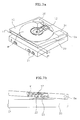
- an ultraslim slot-in type drive device comprises a top link plate 10 and a main body 20, wherein the main body 20 is pivotally coupled with one end of the top link plate 10 via a hinge 10a.
- the box-shaped top link plate 10 allows a recording medium (M) to slide into and exit from the inside of the plate through a slot 11 formed at one side of the plate.
- a clamp 12 for clamping the recording medium is rotatably formed within the upper portion of the top link plate 10, while the lower surface of the top link plate 10 is sectionally cut out, allowing a turntable 22 and a pickup part 23 of the main body 20 (described later) to contact the bottom surface of the recording medium.
- the box-shaped main body 20 is formed at the front with a plurality of manipulating buttons 21 for a functional manipulation.
- the top portion of the main body 20 is formed with the turntable 22 and pickup part 23, in which the turntable 22 rotates the recording medium (M) and the pickup part 23 reads or records the data from the recording surface of the recording medium (M).
- the main body 20 is equipped therein with ascent and descent devices 30 and 31 for ascending and desending the top link plate 10.
- the ascent and descent devices 30 and 31 may be any type of device as long as the device can lift a matter up and down by using, for instance, a lever, gear device, motor or the like.
- FIG 6 is a schematic block flowchart regarding the driving control circuit of the drive device, illustrated in FIG 4.
- the flowchart includes a manipulator 40, detector 50, signal processor 60, controller 70, conveyor 80, ascent and descent driver 90, turntable driver 100, and feeder driver 110.
- the manipulator 40 After a manipulating button 21 equipped at the front of the main body 20 is manipulated, the manipulator 40 generates a corresponding manipulation signal and this signal is then inputted into the controller 70.
- the detector 50 detects the insertion of the recording medium (M) into the inlet of the slot 11 of the top link plate 10 and also detects the movement of the recording medium (M) towards the installation portion of the clamp 12, respectively, and generates the corresponding detection signal.
- the signal processor 60 processes the signal, which is read from the recording medium (M) via the pickup part 23, and inputs the signal to the controller 70.
- the signal processor 60 also processes the signal of recording data outputted from the controller 70 and outputs the signal to the pickup part 23.
- the controller 70 controls the pickup part 23, signal processor 60, conveyor 80, ascent and descent driver 90, turntable driver 100, and feeder driver 110 in response to the signal inputted from the manipulator 40 and detector 50.
- the conveyor 80 delivers the recording medium (M) towards the clamp 12 portion when the recording medium is inserted into the inlet of the slot 11 of the top link plate 10, and likewise delivers the recording medium (M) from the clamp 12 portion to the inlet of the slot 11 according to the control of the controller 70.
- the conveyor 80 includes a moving device for holding and delivering the recording medium (M), and a power generating device for providing power to the moving device.
- the ascent and descent driver 90 activates the ascent and descent devices 30 and 31 for ascending and descendng the top link plate 10 in response to the control of the controller 70.
- the turntable driver 100 activates the turntable 22 according to the control of the controller 70.
- the feeder driver 110 includes a feeder, which moves the pickup part 23 to a prescribed direction in relation to the recording surface of the recording medium (M).
- the feeder driver 110 moves the pickup part 23 by activating the feeder according to the control of the controller 70.
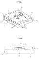
- the top link plate 10 when the recording medium (M) is not installed inside the slot 11 of the top link plate 10, the top link plate 10 is ascended via the ascent and descent devices 30 and 31. That is because, once the top link plate 10 descends, the clamp 12 and turntable 22 are engaged with each other, preventing the recording medium (M) from being delivered towards the clamp 12 portion by being jammed therebetween.
- the detector 50 detects it and generates a detection signal, and the controller 70 controls the conveyor 80 according to the signal.
- the conveyor 80 according to the control of the controller 70 delivers the recording medium (M) to the clamp 12 portion.
- the controller 70 controls the ascent and descent driver 90 to lower the top link plate 10.
- the ascent and descent driver 90 activates the ascent and descent devices 30 and 31 according to the control of the controller 70 for descending the top link plate 10, thereby the clamp 12, recording medium (M), and turntable 22 engage each other as illustrated in FIGS. 8a and 8b.
- the turntable 22 rotates and the recording medium (M) spins as the controller 70 controls the turntable driver 100.
- the controller 70 moves the pickup part 23 by controlling the feeder driver 110, and simultaneously reads or records the signal from the recording surface of the recording medium (M) via the signal processor 60.
- the controller 70 stops the rotation of the turntable 22 by controlling the turntable driver 100 in response to the generation of the corresponding manipulation signal from the the manipulator 40.
- the controller 70 activates the ascent and descent devices 30 and 31 by controlling the ascent and descent driver 90, the top link plate 10 ascends and the recording medium (M) is released from a locked state with the clamp 12 and turntable 22.
- the controller 70 controls the conveyor 80 and delivers the recording medium (M) towards the inlet of the slot 11.
- the exemplary embodiment of the present invention separates the top link plate 10 from the main body 20. That is, when the recording medium is inserted, the top link plate 10 is ascended for preventing the recording medium from being jammed during the movement into the slot 11. The top link plate 10 is then descended for clamping the recording medium, such that a height ( ⁇ h) required to deliver the recording medium without being caught in the slot 11 may be eliminated, enabling the device to reduce its thickness.
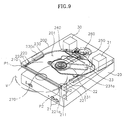
- the structure of a top link plate 200 in the ultraslim slot-in type drive device is different from the embodiment of FIG 4, especially, the recording medium moving mechanism of the inside of the top link plate 200.
- the structure of the main body 20 is identical to the embodiment of FIG 4. Therefore, the same element numerals are provided in relation to each construction parts of the main body 20, and thus, explanation of these elements will be omitted.
- the top link plate 200 includes a pair of stoppers 210, 211 and a pair of resilient members 220, 221 at both walls of the inlet of a slot 201.
- a pair of guiding levers 230, 231 is mounted at both walls of the inside of the slot 201.
- a medium detector 240 and a disk lever 250 are mounted at one end of the inside slot 201.
- the stoppers 210 and 211 made with a material having a high frictional coefficient are installed to contact with the lateral surfaces of the recording medium. Thus, when the recording medium is released, the stoppers frictionally hold and prevent the recording medium from protruding out from the slot 201 via the elasticity of resilient members 220 and 221.
- the pair of resilient members 220 and 221 is designed to protrude out at one side by bending a plate spring and a resilient force is generated towards both oblique directions on the basis of the protruded parts 220a and 221 a.
- Each protruded part 220a and 221a is placed to be in contact with the lateral surface of the recording medium.
- the pair of guiding levers 230 and 231 is respectively formed with an elongated concave groove into which the lateral surface of recording medium is inserted and guided.
- the levers protruding out at all times are pulled back into the case of the lever actuating parts 230a, 231a by the lever actuating parts 230a and 231a, which operate via the controller (not shown).
- the guiding levers 230 and 231 guide the recording medium for being stably delivered. Even in the event that the drive device is mounted in a vertical type and the recording medium is vertically installed, or the like, the guiding levers support the recording medium to prevent the medium from tilting or falling. Furthermore, once the top link plate 200 descends, the levers are configured to quickly be pulled inside the case of the lever actuating parts 230a and 231a for a smooth revolution of the recording medium.
- the guiding levers 230 and 231 in another embodiment of the present invention interact with the top link plate 200 and recede back without the aid of a separate power generating device but via a device mechanism, which interacts with the top link plate 200 when the top link plate 200 is descended.
- the medium detector 240 is equipped to lower the top link plate 200 and hold the recording medium when the recording medium is centrally inserted.
- the medium detector detects the complete insertion of the recording medium and inputs the detection signal to the controller and the medium detector quickly recedes back for a smooth revolution of the recording medium when the top link plate 200 is descended.
- the disk lever 250 operates via a lever actuating mechanism 260, which is activated via the controller, and releases the recording medium by pushing the recording medium towards the inlet of the slot 201.
- a clamp 270 for clamping the recording medium is rotatably formed within the upper portion of the top link plate 200, while the lower surface of the top link plate 200 is sectionally cut out, allowing the turntable 22 and pickup part 23 of the main body 20 to contact the bottom surface of the recording medium.
- both end points P1 and P2 of the diameter of the recording medium pass through the protruded parts 220a and 221a of resilient members 220 and 221 and the resilience of the resilient members 220 and 221 is applied in a positive direction, thererby the recording medium slides down into the portion of the clamp 270 of the slot 201 via the resilient force of the resilient members 220 and 221.
- the medium detector 240 detects the movement of the recording medium and the controller activates the ascent and descent devices 30 and 31 for descending the top link plate 200.
- the controller activates the lever actuating parts 230a and 231a in order to pull the guiding levers 230 and 231 into the case of the lever actuating parts 230a and 231a to prevent any interruption of the revolution of the recording medium, and then the turntable 22 and pickup part 23 start their operation.
- the controller detects the command signal and ceases the rotation of the turntable 22 and activates the lever actuating parts 230a and 231a to allow the guiding levers 230 and 231 to be restored to their original positions.
- the recording medium is guided and then the top link plate 200 ascends by the operation of the ascent and descent devices 30 and 31.
- the disk lever 250 rotates towards the inlet of the slot 201 and pushes the recording medium to lead both end points P1 and P2 of the diameter of the recording medium to pass through the protruded parts 220a and 221 a of the resilient members 220 and 221.
- both end points P1 and P2 of the diameter of the recording medium pass through the protruded parts 220a and 221a of the resilient members according to the operation of the disk lever 250, the resilience of the resilient members 220 and 221 is applied inversely, and the recording medium is pulled out towards the inlet direction of the slot 201 by the resilient force of the resilient members 220 and 221.
- the recording medium does not protrude out from the slot 201 but is held at the inlet of the slot 201.
- the second embodiment of the present invention utilizes elastic force from the resilient member rather than a moving mechanism using electrical power for delivering the recording medium, thus making it possible for this embodiment to be reduced in thickness compared to the embodiment of FIG 4, which adopts the power moving mechanism ( ⁇ t0> ⁇ t1> ⁇ t2).
- the moving mechanism using electrical power to deliver the recording medium requires a holder for holding the recording medium at both sides, a roller for carrying the medium, and a power transmitting device for activating the holder and roller, thus requiring a certain additional thickness.
- the second embodiment of the present invention may be performed without recourse to the holder, roller and power transmitting devices, but a certain amount of space would be required to permit the recording medium to slide into the slot, resulting in a thinner device.
- the top link plate is separated from the main body in the present invention such that when the recording medium is inserted into the slot of the top link plate, the top link plate is in an ascent state to prevent the recording medium from being jammed in the slot during the movement, and then the top link plate descends to clamp the recording medium. Therefore, no additional height is required for permitting the recording medium to be inserted into the slot without being caught therein and the device is greatly reduced in thickness.
- the moving mechanism constructed to move the recording medium via resilient force of the resilient member is provided without actual use of a holder for holding the recording medium, a roller for moving the medium, and a power transmitting device for activating the holder and roller, thus contributing to a narrower space for delivering the recording medium and diminished overall thickness of the device.
Landscapes
- Feeding And Guiding Record Carriers (AREA)
- Holding Or Fastening Of Disk On Rotational Shaft (AREA)
Applications Claiming Priority (2)
| Application Number | Priority Date | Filing Date | Title |
|---|---|---|---|
| KR2004007516 | 2004-02-05 | ||
| KR1020040007516A KR20050079335A (ko) | 2004-02-05 | 2004-02-05 | 초박형 슬롯인타입 드라이브 장치 |
Publications (2)
| Publication Number | Publication Date |
|---|---|
| EP1562191A2 true EP1562191A2 (de) | 2005-08-10 |
| EP1562191A3 EP1562191A3 (de) | 2007-08-22 |
Family
ID=34676004
Family Applications (1)
| Application Number | Title | Priority Date | Filing Date |
|---|---|---|---|
| EP04256928A Withdrawn EP1562191A3 (de) | 2004-02-05 | 2004-11-09 | Ultradünne Laufwerkvorrichtung vom Schlitz-Typ |
Country Status (6)
| Country | Link |
|---|---|
| US (1) | US20050174897A1 (de) |
| EP (1) | EP1562191A3 (de) |
| JP (1) | JP2005222670A (de) |
| KR (1) | KR20050079335A (de) |
| CN (1) | CN1652242A (de) |
| TW (1) | TWI266286B (de) |
Family Cites Families (15)
| Publication number | Priority date | Publication date | Assignee | Title |
|---|---|---|---|---|
| US3658347A (en) * | 1966-12-12 | 1972-04-25 | Cheeseboro Products Corp | Slot-loading portable record player |
| US4499573A (en) * | 1981-07-20 | 1985-02-12 | Tokyo Shibaura Denki Kabushiki Kaisha | Disc rotating apparatus |
| US4561084A (en) * | 1982-06-04 | 1985-12-24 | Hitachi, Ltd. | Disk loading and unloading system |
| JPS5987676A (ja) * | 1982-11-10 | 1984-05-21 | Victor Co Of Japan Ltd | 回転記録媒体再生装置 |
| BE901937A (fr) * | 1985-03-14 | 1985-07-01 | Staar Sa | Dispositif d'insertion et d'ejection automatique de supports d'informations. |
| JP3325820B2 (ja) * | 1997-11-29 | 2002-09-17 | タナシン電機株式会社 | ディスク再生機のディスク搬送装置 |
| JPH11259943A (ja) * | 1998-03-09 | 1999-09-24 | Nakamichi Corp | ディスク移送装置 |
| EP0997897A3 (de) * | 1998-10-27 | 2000-06-07 | Hewlett-Packard Company | Ladevorrichtung mit Schlitz für optische Plattenantriebsvorrichtung |
| US6577579B1 (en) * | 1999-02-23 | 2003-06-10 | Matsushita Electric Industrial Co., Ltd. | Disc drive apparatus of slot loading type |
| CN1154102C (zh) * | 1999-10-07 | 2004-06-16 | 索尼株式会社 | 光磁盘记录及/或再生装置 |
| JP4071410B2 (ja) * | 1999-11-12 | 2008-04-02 | パイオニア株式会社 | ディスクプレーヤ |
| JP3685047B2 (ja) * | 1999-12-03 | 2005-08-17 | ティアック株式会社 | 記録媒体装着装置 |
| JP2001256703A (ja) * | 2000-03-13 | 2001-09-21 | Alps Electric Co Ltd | ディスク装置 |
| KR100904244B1 (ko) * | 2001-04-05 | 2009-06-25 | 소니 가부시끼 가이샤 | 디스크 기록 재생 장치 |
| JP3891021B2 (ja) * | 2002-03-28 | 2007-03-07 | ソニー株式会社 | 情報処理装置 |
-
2004
- 2004-02-05 KR KR1020040007516A patent/KR20050079335A/ko not_active Abandoned
- 2004-03-17 US US10/801,589 patent/US20050174897A1/en not_active Abandoned
- 2004-03-23 TW TW093107841A patent/TWI266286B/zh not_active IP Right Cessation
- 2004-03-24 JP JP2004087780A patent/JP2005222670A/ja active Pending
- 2004-03-30 CN CNA200410030623XA patent/CN1652242A/zh active Pending
- 2004-11-09 EP EP04256928A patent/EP1562191A3/de not_active Withdrawn
Also Published As
| Publication number | Publication date |
|---|---|
| EP1562191A3 (de) | 2007-08-22 |
| KR20050079335A (ko) | 2005-08-10 |
| JP2005222670A (ja) | 2005-08-18 |
| US20050174897A1 (en) | 2005-08-11 |
| TWI266286B (en) | 2006-11-11 |
| TW200527384A (en) | 2005-08-16 |
| CN1652242A (zh) | 2005-08-10 |
Similar Documents
| Publication | Publication Date | Title |
|---|---|---|
| CN100437792C (zh) | 盘装置及盘装置的装载方法 | |
| JP3889666B2 (ja) | ディスク駆動装置 | |
| JPH03256260A (ja) | マルチタイプcdプレーヤシステム | |
| EP1562191A2 (de) | Ultradünne Laufwerkvorrichtung vom Schlitz-Typ | |
| JPH0325325Y2 (de) | ||
| JP3636512B2 (ja) | ディスク再生装置 | |
| CN101567200B (zh) | 光盘装置 | |
| KR100379050B1 (ko) | 디스크 장치 | |
| EP1995727A1 (de) | Plattenspieler und verfahren und programm zur steuerung solch eines plattenspielers | |
| JPS61123051A (ja) | デイスクロ−デイング装置 | |
| JP3847956B2 (ja) | ディスク装置 | |
| JP3057604B2 (ja) | 光学式ディスク再生装置のピックアップ光軸調節装置 | |
| US7540002B2 (en) | Disc loading device with separate conveying units for the disc and the disc cartridge containing the disc | |
| KR20050079336A (ko) | 초박형 슬롯인타입 드라이브 장치 | |
| JP2551156Y2 (ja) | クランパー制御機構 | |
| JPH11167760A (ja) | ディスク装置 | |
| JP4230155B2 (ja) | ディスクローディング装置 | |
| JP3276875B2 (ja) | ディスクローディング装置 | |
| US7367033B2 (en) | Device for scanning a disc-shaped data carrier, comprising a transport system for transporting the data carrier | |
| JP2952176B2 (ja) | 記録媒体の記録再生装置 | |
| JP2952177B2 (ja) | 記録媒体の記録再生装置 | |
| EP0817184A2 (de) | Automstischer Plattenwechsler mit Plattenspieler-Trägervorrichtung | |
| JP3073143B2 (ja) | 記録媒体の収納および引出装置 | |
| JP2952178B2 (ja) | 記録媒体の記録再生装置 | |
| JPH0273560A (ja) | カセット挿入装置 |
Legal Events
| Date | Code | Title | Description |
|---|---|---|---|
| PUAI | Public reference made under article 153(3) epc to a published international application that has entered the european phase |
Free format text: ORIGINAL CODE: 0009012 |
|
| AK | Designated contracting states |
Kind code of ref document: A2 Designated state(s): AT BE BG CH CY CZ DE DK EE ES FI FR GB GR HU IE IS IT LI LU MC NL PL PT RO SE SI SK TR |
|
| AX | Request for extension of the european patent |
Extension state: AL HR LT LV MK YU |
|
| PUAL | Search report despatched |
Free format text: ORIGINAL CODE: 0009013 |
|
| AK | Designated contracting states |
Kind code of ref document: A3 Designated state(s): AT BE BG CH CY CZ DE DK EE ES FI FR GB GR HU IE IS IT LI LU MC NL PL PT RO SE SI SK TR |
|
| AX | Request for extension of the european patent |
Extension state: AL HR LT LV MK YU |
|
| AKX | Designation fees paid | ||
| REG | Reference to a national code |
Ref country code: DE Ref legal event code: 8566 |
|
| STAA | Information on the status of an ep patent application or granted ep patent |
Free format text: STATUS: THE APPLICATION IS DEEMED TO BE WITHDRAWN |
|
| 18D | Application deemed to be withdrawn |
Effective date: 20080223 |