EP1562222A2 - Metallhalogenidlampe und Beleuchtungsvorrichtung unter Verwendung derselben - Google Patents
Metallhalogenidlampe und Beleuchtungsvorrichtung unter Verwendung derselben Download PDFInfo
- Publication number
- EP1562222A2 EP1562222A2 EP04257618A EP04257618A EP1562222A2 EP 1562222 A2 EP1562222 A2 EP 1562222A2 EP 04257618 A EP04257618 A EP 04257618A EP 04257618 A EP04257618 A EP 04257618A EP 1562222 A2 EP1562222 A2 EP 1562222A2
- Authority
- EP
- European Patent Office
- Prior art keywords
- lamp
- arc tube
- metal halide
- halide lamp
- mercury
- Prior art date
- Legal status (The legal status is an assumption and is not a legal conclusion. Google has not performed a legal analysis and makes no representation as to the accuracy of the status listed.)
- Withdrawn
Links
Images





Classifications
-
- H—ELECTRICITY
- H01—ELECTRIC ELEMENTS
- H01J—ELECTRIC DISCHARGE TUBES OR DISCHARGE LAMPS
- H01J61/00—Gas-discharge or vapour-discharge lamps
- H01J61/02—Details
- H01J61/30—Vessels; Containers
- H01J61/33—Special shape of cross-section, e.g. for producing cool spot
-
- H—ELECTRICITY
- H01—ELECTRIC ELEMENTS
- H01J—ELECTRIC DISCHARGE TUBES OR DISCHARGE LAMPS
- H01J61/00—Gas-discharge or vapour-discharge lamps
- H01J61/02—Details
- H01J61/12—Selection of substances for gas fillings; Specified operating pressure or temperature
- H01J61/125—Selection of substances for gas fillings; Specified operating pressure or temperature having an halogenide as principal component
-
- H—ELECTRICITY
- H01—ELECTRIC ELEMENTS
- H01J—ELECTRIC DISCHARGE TUBES OR DISCHARGE LAMPS
- H01J61/00—Gas-discharge or vapour-discharge lamps
- H01J61/02—Details
- H01J61/30—Vessels; Containers
- H01J61/34—Double-wall vessels or containers
-
- H—ELECTRICITY
- H01—ELECTRIC ELEMENTS
- H01J—ELECTRIC DISCHARGE TUBES OR DISCHARGE LAMPS
- H01J61/00—Gas-discharge or vapour-discharge lamps
- H01J61/82—Lamps with high-pressure unconstricted discharge having a cold pressure > 400 Torr
- H01J61/827—Metal halide arc lamps
Definitions
- the present invention relates to a metal halide lamp and a lighting apparatus using the same.
- a metal halide lamp is commonly used for outdoor lighting, high ceiling lighting, and so on.
- a metal halide lamp using translucent ceramic as a material for the envelope of the arc tube has been developed actively.
- This type of metal halide lamp is hereinafter called "a ceramic metal halide lamp”.
- the arc tube having the envelope made of translucent ceramic has lower chemical reactivity with a halide enclosed within the arc tube than an arc tube having an envelope made of silica glass. This means that the arc tube having the envelope made of translucent ceramic is capable of raising the bulb wall loading. Therefore, the arc tube having the envelope made of translucent ceramic has an advantage that it can realize high luminous efficiency.
- this halide lamp requires less amount of metallic mercury because of its long and thin shape, and therefore it is ecologically friendly as well. For instance, when the rated lamp wattage of the lamp is 150W, only 0.7mg ( ⁇ 1.6mg/cm 3 ) is required to gain 80V-100V of lamp voltage.
- the inventors of the present invention proved that although the halide lamp realizes relatively high luminous efficiency, its lamp voltage rises during the lighting, and the light goes off unexpectedly (lighting failure) because the discharge can not be sustained. Such a problem occurred even when a rectangular wave voltage was applied to the lamp with use of an electronic ballast as well as when a sine wave voltage at commercial frequency was applied.
- the cause of this problem is as follows.
- the shape of the arc tube becomes long and thin when L / D is large, and the temperature inside the arc tube becomes extremely high because of the short distance from the internal surface of the arc tube and the arc.
- the amount of a luminescent metal contributing to the discharge decreases. Accordingly, the amount of the free halogen increases, which makes the vapor pressure in the arc tube extremely high. This raises the lamp voltage markedly.
- the inventors found that when the inventors lit up the above-described ceramic metal halide lamp with use of a common magnetic ballast for performing dimming control , the lamp voltage unexpectedly changed according to the change of the input voltage. In this case, the ceramic and the halide reacted together strongly, the lamp voltage rose, and the lighting failure occurred.
- the object of the present invention is therefore to provide a metal halide lamp that realizes high luminous efficiency with suppressed rise in a lamp voltage during lighting and has less piece-to-piece variation in a lamp voltage, and a lighting apparatus using the same.
- a metal halide lamp comprising an arc tube having an envelope made of translucent ceramic and a pair of electrodes disposed in the envelope, wherein a sodium (Na) halide, a mercury (Hg) halide, and one or more lanthanide halides are enclosed within the arc tube, the lanthanide halides including at least one of a cerium (Ce) halide and a praseodymium (Pr) halide, and L / D ⁇ 1, where D (mm) is an inside diameter of the arc tube, and L (mm) is a distance between the electrodes.
- the inside diameter of the arc tube D in this Specification is derived in the following way. Firstly, calculate the area of a portion of the internal surface of the arc tube, which surrounds a portion of the axis of the arc tube. This portion of the axis indicates the distance L between the electrodes. Secondly, divide the calculated internal area by the distance L .
- the metal halide lamp can realize high luminous efficiency, and prevent a lighting failure during the lighting caused by rise in a lamp voltage. Also, the lamp can reduce a piece-to-piece variation in the lamp voltage.
- H hg (mol) is an amount of a halogen included in the mercury halide
- H ln (mol) is an amount of a halogen included in the lanthanide halides.
- the lamp can surely prevent the lighting failure during the lighting caused by rise in the lamp voltage, and prevent a breakage of the electrodes as well.
- the mercury halide may be a mercurous halide.
- the amount of the enclosed mercury can be reduced more.
- the lamp can realize extremely high luminous efficiency, further suppress the rise in the lamp voltage, and prevent a blackening on an internal surface of the arc tube, which ruins the appearance.
- a bulb wall loading may be in a range of 28 W/cm 2 to 33 W/cm 2 .
- the lamp can realize all of a high luminous efficiency, a long life of the lamp, and a high color rendering.
- the metal halide lamp further comprises a bulb made of hard glass surrounding the arc tube, wherein a pressure in a space between the bulb and the arc tube is equal to or less than 5 ⁇ 10 4 Pa at 300K.
- the lamp can prevent the decreasing of the luminous efficiency.
- a lighting apparatus comprising: the stated metal halide lamp; and an electronic ballast operable to light the metal halide lamp.
- the lighting apparatus can realize high luminous efficiency, and prevent the lighting failure during the lighting caused by rise in the lamp voltage. Also, the lighting apparatus can reduce the piece-to-piece variation in lamp voltage.
- the lighting apparatus may comprise: the stated metal halide lamp, and an electronic ballast operable to perform a dimming control of the metal halide lamp in a range from 25% to 100% of a rated lamp wattage.
- the lighting apparatus can realize high luminous efficiency, and prevent the lighting failure during the lighting caused by the rise in the lamp voltage . Also, the lighting apparatus can reduce the piece-to-piece variation in the lamp voltage. Further, the lighting apparatus can suppress a fluctuation of the lamp voltage caused by a change of an input lamp voltage at a time of dimming control, and suppress a change of a color temperature.
- H hg (mol) is an amount of a halogen included in the mercury halide
- H t (mol) is a total amount of metal included in all the metal halides enclosed within the arc tube except the mercury halide.
- the lighting apparatus can surely reduce the fluctuation of the lamp voltage and the change of the color temperature at the time of the dimming control.
- the metal halide lamp may be lit with use of a rectangular-wave current.
- the lighting apparatus can suppress a fluctuation of the lamp voltage caused by a change of an input lamp voltage, and stabilize the temperature of the arc tube, and realize evenness of its temperature distribution. As a result, the lighting apparatus can stabilize the vapor pressure of the enclosure in the arc tube, and suppress the raise in the lamp voltage.
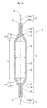
- a metal halide lamp (a ceramic metal halide lamp) 1 of the first embodiment of the present invention with the rated lamp wattage of 150W includes a bulb 3, feeders 4 and 5, an arc tube 6, and a base 7.
- the bulb 3 is made of hard glass or borosilicate glass or the like. One end of the bulb is blocked and the other end is sealed with a flare 2 made of borosilicate glass.
- the feeders 4 and 5 are made of nickel or mild steel, for instance. A portion of each of feeders 4 and 5 is sealed to the flare 2. Also, one end of each of feeders 4 and 5 is drawn into the bulb 3.
- the arc tube 6 is supported by these feeders 4 and 5 in the bulb 3.
- the base 7 is of a screw type (E type) and fixed to the other end of the bulb 3.
- the space in the bulb 3 is a vacuum having approximately 1 ⁇ 10 -1 Pa at a temperature of 300K.
- the other end of the feeder 4 is electrically connected to an eyelet 8 of the base 7, and the other end of the feeder 5 is electrically connected to a shell 9 of the base 7.
- a portion of the feeder 5 drawn into the bulb 3 is covered by a tube 10, which is for preventing photoelectrons from being generated on the surface of the feeder 5.
- a getter 11 is attached to the feeder 5 in order to absorb an impure gas in the bulb 3.
- the arc tube 6 includes an envelope 17 made of polycrystalline alumina, including a main tube 15 and thin tubes 16.
- the main tube 15 includes a cylinder 12, tapers 13, and rings 14.
- the inside diameter D of the cylinder 12 is 4mm.
- the tapers 13 are connected to both ends of the cylinder 12.
- the ring 14 is formed on one end of each taper 13. This end is not the end connected to the cylinder 12.
- the thin tubes 16 are shrinkage-fit to the rings 14 respectively.
- the cylinder 12, the tapers 13, and the rings 14 are integrally and seamlessly formed.
- these members 12, 13, and 14 may be integrally formed by shrinkage-fitting.
- the envelope 17 may be made of translucent ceramics other than polycrystalline alumina, such as yttrium aluminum garnet (YAG), aluminum nitride, yttria, and zirconia.
- YAG yttrium aluminum garnet
- aluminum nitride aluminum nitride
- yttria aluminum nitride
- zirconia zirconia
- arc tube 6 in total, 10mg of praseodymium iodide, sodium iodide, and mercuric iodide are enclosed, and xenon (Xe) is enclosed so as to have 20kPa at a room temperature.
- the amount of the mercuric iodide is 0.7mg, which includes 0.3mg of mercury.
- H hg / H ln is 1.00.
- the capacity of the arc tube 6 is 0.45cc in a state where electrodes 18 are inserted in the thin tubes 16.
- the electrodes 18 are described later.
- a pair of electrodes 18 is disposed so as to have substantially the same axis (an axis A in FIG.2) and substantially opposite to each other.
- a discharge space 19 is formed within the main tube 15.
- the distance L between each electrode 18 is 32mm.
- L / D is 8.
- Each electrode 18 includes an electrode rod 20 made of tungsten having 0.5mm in diameter, and an electrode coil 21 made of tungsten disposed on the tip of the electrode rod 20.
- An electrode inductor 22 is inserted into the thin tube 16. One end of the electrode inductor 22 is electrically connected to the electrode 18. The other end of the electrode inductor 22, where there is a gap formed between the internal surface of the thin tube 16 and a second member 24b included in the electrode inductor 22, is sealed with an inpoured glass frit 23. The second member 24b is described later.
- the electrode conductor 22 includes a first member 24a and a secondmember 23b.
- the first member 24a is made of molybdenum or conductive cermet, for instance.
- the electrode rod 20 is connected to the first member 24a.
- the second member 24b is made of niobium, for instance. Either of the members 24a and 24b has 0.9mm in diameter. One end of the second member 24b, which is not the end adjoining to the first member 24a, is lead out of the thin tube 16.
- the second member 24b is connected to feeders 4 and 5.
- the inventors had a life test. In this test, the inventors lit up the practical example 1 with alternating current having rectangular wave at frequency 150Hz with use of a publicly known electronic ballast. This is repeated in a predetermined ON/OFF cycle.
- the number of samples is five.
- the inventors also had the same life test as to another metal halide lamp (comparative example 1) that has the same structure as the practical example 1 except that metallic mercury in a liquid form is enclosed within the arc tube 6 instead of mercuric iodide.
- comparative example 1 again, the inventors lit up the comparative example 1 with alternating current having rectangular wave at frequency 150Hz with use of the same publicly known electronic ballast. This also is repeated in the predetermined ON/OFF cycle.
- the life test revealed that the lamp voltage rarely rose with all the samples of the practical example 1 until 1000 hours passed from the start of the lighting. Further, when 12000 hours, which is the rated lifetime, passed from the start of the lighting, the lamp voltage had risen by not more than 20V. This is not a problem in actual use.
- the lamp voltage had risen by not less than 30V when 500 to 1000 hours passed from the start of the lighting. Further, the re-striking potential at the start of lighting became markedly high, and two out of five samples could not be lit up. Examining these two samples, the inventors found that there is a trace of strong chemical reaction with metal iodide on the internal surface of the main tube 15 in the vicinity of the electrode 18.
- the inventors manufactured metal halide lamps (practical examples 2 to 11) , each having the rated lamp wattage of 150W and the same structure as the practical example 1 except that the total amount of the enclosed praseodymium iodide, sodium iodide, and mercuric iodide and the ratio H hg / H ln vary from each other as shown in FIG.4, which is described later.
- the inventors measured the lamp voltages during the early stage of the lighting (for 100 hours from the start of the lighting) as to the practical examples 2 to 11 adding to the practical example 1 and the comparative example 1. The following is the result.
- the lamp voltages are in a range from 80V to 100V. This is because the mercury halide is in solid form and easy to handle with, and therefore the amount of the halide can be controlled accurately and stability of the amount of the halide enclosed in each lamp can be realized.
- the practical examples require 0.7mg of mercuric halide including only 0.3mg of mercury to gain lamp voltage in a range from 80V to 100V. This amount is less than a half of the amount of the mercury in a liquid form enclosed within the comparative example 1 (requiring 0.7mg of mercury to gain the same lamp voltage).
- the comparative example 1 within which mercury as a liquid metal is enclosed, has a piece-to-piece variation in the lamp voltage, which is in the range from 60V to 115V. This is because the amount (the designed amount) of the enclosed mercury as a liquid metal is as small as 0.7mg. Even if the mercury douser has only a small piece-to-piece variation in the amount of the enclosure, the small amount (0.7mg) makes the variation relatively large. As a result, the amount of the enclosure varies greatly for each lamp.
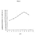
- L / D is the ratio of the distance L between the electrodes 18 to the inside diameter D , the values of L / D are numbered from 1 to 20 respectively.
- FIG.3 shows the luminous efficiencies (lm/W) of the manufactured lamps.
- metal halide lamp with high luminous efficiency and high color rendering having the rated lamp wattage of 150W, generally has 90 lm/W to 95 lm/W of luminous efficiency. It is generally said that human beings can visually recognize an increase of luminance when luminous flux (lm) is increased by not less than 10%.
- the luminous efficiency becomes more than 105 lm/W when L / D ⁇ 1 is satisfied. This increased luminous efficiency over the conventional metal halide lamp can be visually recognized by a man as an increase of the brightness.
- the luminous efficiency becomes more than 115 lm/W when L / D ⁇ 4 is satisfied. This increased luminous efficiency can be visually recognized as increase of the brightness more clearly. Further, the rise in the lamp voltage is only 18V when 12000 hours passed from the start of the lighting. Therefore, it is preferable that a relational expression L / D ⁇ 4 is satisfied in order to increase the luminous efficiency over the conventional metal halide lamp to an extent where the luminous efficiency can be visually recognized as an increase of the brightness very clearly, and suppress the rise in the lamp voltage.
- This blackening is caused by tungsten, which is the material of the electrodes, being diffused and attaching to the internal surface of the arc tube 6.
- tungsten which is the material of the electrodes, being diffused and attaching to the internal surface of the arc tube 6.
- a possible reason why the tungsten diffused is that the value of L / D becomes too large to realize smooth transition to the arc discharge and the sputtering occurred.
- the tungsten is diffused by this sputtering.
- L / D ⁇ 10 is satisfied in order to gain high luminous efficiency and not to ruin the appearance.
- the luminous efficiency becomes more than 130 lm/W when 7 ⁇ L / D ⁇ 9 is satisfied, and the rise in the lamp voltage is only 13V when 12000 hours passed from the start of the lighting. Therefore, it is preferable that 7 ⁇ L / D ⁇ 9 is satisfied in order to gain higher luminous efficiency and suppress the rise in the lamp voltage even more.
- the bulb wall loading (the rated lamp wattage per unit area on the internal surface of the arc tube) is set in a range from 20W/cm 2 to 35W/cm 2 in order to realize both high luminous efficiency and high color rendering, and suppress the chemical reaction between the halide and the glass frit 23.
- the bulb wall loading is less than 20W/cm 2 , high luminous efficiency and high color rendering might not be realized at the same time.
- the bulb wall loading is more than 35W/cm 2 , the halide and the glass frit 23 react chemically together and might cause a leak.
- the bulb wall loading is set in a range from 28 W/cm 2 to 33 W/cm 2 .
- a relational expression L / D ⁇ 1 is satisfied for realizing high luminous efficiency.
- L / D 8 namely when the arc tube 6 is long and thin
- the vapor pressure of iodine in the arc tube 6 is prevented from becoming extremely high. This is because excess iodine is previously enclosed within the arc tube 6, which keeps the equilibrium state of the chemical reaction between polycrystalline alumina and metal iodide, and therefore the iodine is not produced.
- the lamp voltage is prevented from rising up and causing lighting failure.
- mercury as a halide in a solid state is enclosed. This improves the accuracy of the amount of the enclosure during the manufacturing process, and decreases the piece-to-piece variation in the lamp voltage.
- the lamp requires 0.7mg of a mercury halide, such as a mercuric halide including only 0.3mg of mercury, to gain lamp voltage within an appropriate range (80V-100V) .
- This amount of the mercury is less than a half of the case where metal mercury in a liquid form is enclosed, in which 0.7mg of mercury is required to gain the same lamp voltage. This means that the lamp is capable of decreasing the amount of the mercury as the enclosure, and reducing an environmental burden.
- the lamp realizes much higher luminous efficiency than the conventional metal halide lamp (with 90 lm/W - 95 lm/W), because a relational expression 4 ⁇ L / D ⁇ 10 is satisfied in particular.
- the lamp further suppresses the rise in the lamp voltage, and prevents the blackening occurring on the internal surface of the arc tube, which ruins the appearance.
- mercurous iodide when mercurous iodide is enclosed as a mercury halide instead of mercuric iodide, 0.4mg of mercurous iodide including only 0.2 mg of mercury is required to gain lamp voltage in a range from 80V to 100V, which means that the amount of mercury as the enclosure is further reduced. Therefore, for reducing the amount of mercury as the enclosure, it is preferable that mercurous iodide is enclosed as a mercury halide.
- H hg (mol) is the amount of halogen included in a mercury halide, such as mercuric iodide
- H ln (mol) is the amount of halogen included in a lanthanide halide, such as praseodymium iodide.
- H hg (mol) is the amount of halogen included in a mercury halide, such as mercuric iodide
- H ln (mol) is the amount of halogen included in a lanthanide halide, such as praseodymium iodide.
- the inventors manufactured the metal halide lamps (the practical examples 2 to 11), each having the rated lamp wattage of 150W and the same structure as the practical example 1 except that the total amount of the enclosed praseodymium iodide, sodium iodide, and mercuric iodide and the ratio H hg / H ln vary from each other as shown in FIG.4. Then, the inventors had a life test. In this test, the inventors lit up the practical examples 2 to 11 adding to the practical example 1 and the comparative example 1, with alternating current having rectangular wave at frequency 150Hz with use of a publicly known electronic ballast. This is repeated in a predetermined ON/OFF cycle. Then, the inventors measured the probability of the lighting failure caused by the rise in the lamp voltage and the probability of the breakage of the electrodes 18 until 12000 hours passed from the start of the lighting. FIG.4 shows the result.
- the practical examples and the comparative examples have five samples for each.
- the denominators in “probability of lighting failure” and “probability of breakage of electrodes” represent the number of samples, and the numerators represent the number of samples in which the lighting failure or the breakage of the electrodes is observed.
- FIG.4 shows, when a relational expression 0.05 ⁇ H hg / H ln ⁇ 2.00 was satisfied, no lighting failure caused by the rise in the lamp voltage and the breakage of the electrodes 18 occurred in the practical examples 1 and 4 to 9.
- this relational expression is applicable not only to the case where the mercuric iodide is used, but also to the case where a mercury halide, such as mercuric bromide and mercurous iodide. Also, it is applicable not only to the case where the praseodymium iodide is used, but also to the case where a lanthanide halide, such as praseodymium bromide and later-described cerium iodide.
- the pressure is more than 5 ⁇ 10 4 Pa at 300K, the luminous efficiency decreases not less than 51m/W from the practical example 1 (1 ⁇ 10 3 Pa at 300K) for instance. This is because the heat of the arc tube 6 conducts to the bulb 3 via the gas in the space, and the heat is emitted to the outer space. It is much preferable that the pressure is not more than 1 ⁇ 10 3 Pa at 300K.
- a metal halide lamp of the second embodiment of the present invention having the rated lamp wattage of 150W has the same structure as the halide lamp 1 of the first embodiment of the present invention having the rated lamp wattage of 150W except that cerium iodide is enclosed within the arc tube instead of praseodymium iodide.
- the total amount of cerium iodide, sodium iodide, and mercuric iodide is 10mg, and the mole ratio among these enclosures is 1:10.5:0.72.
- the "mole ratio” mentioned here means the mole ratio of only metals included in a metal halide.
- H hg mol
- H ln mol
- the lighting failure caused by the rise in the lamp voltage can be prevented.
- mercury as a halide in a solid state is enclosed, and this improves the accuracy of the amount of the enclosure during the manufacturing process, and decreases the piece-to-piece variation in the lamp voltage.
- the lamp is capable of decreasing the amount of the mercury as the enclosure, and reducing an environmental burden.
- the lamp realizes much higher luminous efficiency than that of the conventional metal halide lamp (90 lm/W - 95 lm/W), because a relational expression 4 ⁇ L / D ⁇ 10 is satisfied in particular. At the same time, the lamp further suppresses the rise in the lamp voltage, and prevents the blackening occurring on the internal surface of the arc tube, which ruins the appearance.
- mercurous iodide as a mercury halide is enclosed.
- the bulb wall loading is set in a range from 20W/cm 2 to 35W/cm 2 in order to realize both high luminous efficiency and high color rendering, and suppress the chemical reaction between the halide and the glass frit 23.
- the bulb wall loading is set in a range from 28 W/cm 2 to 33 W/cm 2
- the pressure in the space between the bulb 3 and the arc tube 6 is not more than 5 ⁇ 10 4 Pa at 300K for preventing the decrease of the luminous efficiency. In particular, it is preferable that the pressure is not more than 1 ⁇ 10 3 Pa at 300K.
- a lighting apparatus pertaining to the third embodiment of the present invention includes the metal halide lamp 1 (practical example 1) pertaining to the first embodiment of the present invention and an electronic ballast 25.
- the metal halide lamp 1 has the rated lamp wattage of 150W.
- the electronic ballast 25 can change the input lamp wattage in a range from 25% to 100% of the rated lamp wattage.
- the electronic ballast 25 is connected to a 60Hz AC power supply 26.
- the AC power supply 26 supplies alternating current at 60Hz with a fixed voltage to the electronic ballast 25.
- the electronic ballast 25 includes a filtering circuit 27, a power conditioning circuit (a step-down chopper) 28, a full-bridge circuit (a full-bridge inverter) 29, an igniter 30, and a dimming control circuit 31.
- the filtering circuit 27 is for controlling power-factor and preventing electromagnetic wave interference, and connected to the AC power supply 26.
- the filtering circuit 27 receives electric power from the AC power supply 26, sustains a simple harmonic current having the same phase as a line voltage, and synchronously converts the line voltage having alternating polarity to a voltage having fixed polarity. At this time, the filtering circuit 27 steps up the line voltage to a voltage larger than a peak line voltage if needed. Also, the filtering circuit 27 limits the electromagnetic emission during the conversion.
- the power conditioning circuit 28 receives the simple harmonic current and the voltage having fixed polarity from the filtering circuit 27, and generates and outputs a voltage and a current having fixed polarity, which are conditioned by the dimming control circuit 31 connected to the power conditioning circuit 28.
- the power conditioning circuit 28 also outputs 100% voltage at the start-up of the metal halide lamp 1, and performs an arc discharge.
- the full-bridge circuit 29 converts the waveform of the fixed voltage outputted by the power conditioning circuit 28 into a low-frequency square wave.
- the igniter 30 generates a starting voltage pulse of 4kV, for instance. After that, the igniter 30 supplies the low-frequency square wave outputted by the full-bridge circuit 29 to the metal halide lamp 1, and lights up the metal halide lamp 1.
- the dimming control circuit 31 conditions the received voltage to be a predetermined voltage according to a reference value which the dimming control circuit 31 internally has.
- FIG.6 A circuit diagram of the electronic ballast 25 is shown in FIG.6.
- the filtering circuit 27 and the full-bridge circuit 29 is the same as the conventional technique, and therefore their descriptions are omitted here.
- the power conditioning circuit 28 includes a resistance R c for detecting the current passing through the metal halide lamp 1.
- the dimming control circuit 31 includes an amplifier 32, a comparison unit 33 , and a driving circuit 34.
- the dimming control circuit 31 monitors a current passing through the resistance R c and converts the detected current to a voltage. (This voltage converted from the current is hereinafter called a "feedback signal 35".)
- the amplifier 32 includes a resistance R 1 , a resistance R 2 , and an error amplifier 36, and stores a reference voltage V ref .
- the feedback signal 35 is inputted into the error amplifier 36 via the resistance R 1 .
- the error amplifier 36 amplifies the feedback signal 35 based on the reference voltage V ref and the resistances R 1 and R 2 .
- the reference voltage V ref By changing the reference voltage V ref , the value of the current passing through the metal halide lamp 1 is set to a desired value. This changes the lamp output and realizes the dimming control.
- the comparison unit 33 includes a comparer 37.
- the amplified feedback signal 35 is inputted to the comparer 37.
- the comparer 37 compares the feedback signal 35 to a sawtooth wave, and generates a switching pulse signal for switching a switch 38 of the power conditioning circuit 28.
- the driving circuit 34 conditions the level of switching pulse signal to be at a predetermined voltage level, and outputs the conditioned switching pulse signal to the switch 38.
- the ON/OFF of the power conditioning circuit 28 is controlled by the switching pulse, and a current at a desired level is supplied to the metal halide lamp 1.
- the inventors measured the change of the color temperature and the fluctuation rate of the lamp voltage after lighting up the lighting apparatus pertaining to the third embodiment of the present invention (hereinafter called the "practical example 12") for 6000 hours without dimming control, and successively changes the input lamp wattage down to 25% (38W) of the rated lamp wattage. The following is the result.
- the change of the color temperature means the change of the color temperature during the early stage of the lighting (until when approximately 100 hours passed from the start of the lighting).
- the fluctuation rate of the lamp voltage means the ratio of the lamp voltage at a time when the dimming control is performed to the lamp voltage at a time when the input lamp wattage is 100% of the rated lamp wattage.
- the number of samples is five.
- the inventors successively changed the input lamp wattage down to 25% (38W) of the rated lamp wattage.
- the change of the color temperature was not more than 300K in every sample, and the change was almost not recognizable with eyes.
- the fluctuation rate is only 5% to 10%.
- the dimming control is performed with lamp wattage not less than 25% of the rated lamp wattage for preventing the lighting failure.
- the lighting apparatus realizes high luminous efficiency, and at the same time, prevents the lighting failure of the metal halide lamp 1 caused by the rise in the lamp voltage. Also, the piece-to-piece variation in the lamp voltage can be decreased. Further, the lighting apparatus is capable of decreasing the amount of the mercury as the enclosure, and reducing an environmental burden.
- the lighting apparatus is capable of suppressing the fluctuation of the lamp voltage caused by the change of the input lamp voltage, and suppressing the change of color temperature.
- the metal halide lamp 1 is lit up with a current having substantially square wave. This reduces the fluctuation of lamp wattage corresponding to the fluctuation of lamp voltage and stabilizes the temperature of the arc tube 6, and at the same time, realizes evenness of the temperature distribution on the arc tube 6. As a result, the lamp can stabilize the vapor pressure of the enclosure in the arc tube 6, and suppress the rise in the lamp voltage.
- H hg (mol) is the amount of halogen included in a mercury halide, such as mercuric iodide
- H t (mol) is the total amount of metal included in enclosed metal halide except a mercury halide, such as praseodymium iodide and sodium iodide.
- FIG.5 and FIG.6 a device shown in FIG.5 and FIG.6 is used as an electronic ballast.
- other publicly known electronic ballast can realize the same effect.
- a metal halide lamp having the rated lamp wattage of 150W is taken as an example.
- other metal halide lamps having the rated lamp wattage in a range from 20W to 400W can realize the same effect.
- a lamp having high rated lamp wattage tends to realize low power loss and high luminous efficiency.
- a lamp having low rated lamp wattage for instance 150W, tends to suffer high power loss and low luminous efficiency. Therefore, the effectiveness varies depending on the value of the rated lamp wattage.
- the present invention can improve the luminous efficiency relatively to the luminous efficiency of the conventional lamp having the same rated lamp wattage.
- lanthanide halide such as lanthanum (La) halide and neodymium (Nd) halide
- La lanthanum
- Nd neodymium
- sodium iodide, and mercuric iodide or mercurous iodide, and at least one lanthanide halide of praseodymium iodide and cerium iodide are enclosed.
- other publicly known metal halide may be enclosed according to a desired color temperature and color rendering.
- metal iodide is taken as an example metal halide.
- other metal halides such as metal bromide can realize the same effect.
- the arc tube 6, which has a shape shown in FIG.1 and FIG.2, is explained.
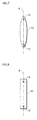
- arc tubes 39, 40, 41, 42, 43, and 44 respectively having shapes shown in FIG.7 to FIG.12 may be used.
- the arc tubes 39 to 44 are bodies of revolution, each having a rotation axis (shown as B in each figure) in the longitudinal direction of the arc tube.
- the thickness of each arc tube is not considered here.
- the shapes of internal and external surfaces of the arc tubes 39 to 44 are as shown in the figures.
- a thin-tube part may be formed if needed in each of the arc tubes 39 to 44 shown in figures.
- the out line of the cross section of the arc tube 39 which is cut along a plane including the rotation axis in longitudinal direction of the arc tube 39, is in a shape of an ellipse.
- This type of arc tube 39 has a simple structure, and therefore it can reduce the production cost. Also, a piece-to-piece variation in the color temperature can be reduced in a case of mass production. Therefore, when a plurality of lamps or lighting apparatuses respectively including such arc tubes are used in the same space for ceiling lighting, for instance, the piece-to-piece variation in the color temperature is not noticeable.
- the out line of the cross section of the arc tube 40 which is cut along a plane including the rotation axis in longitudinal direction of the arc tube 40, is in a shape of a rectangle. This particularly reduces the change of the color temperature.
- the cross section of the out line of the arc tube 41 which is cut along a plane including the rotation axis in longitudinal direction of the arc tube 41, is in a shape of a semicircle at both end portions, and the part connecting those semicircles is in a bow shape, having a depression.
- This arc tube 41 can quicken the initial rise of the light at a time of starting up. Although depending on its design, this arc tube 41 can shorten the time required to gain the rated light output by 10% to 20% as well. Also, its arc curvature is extremely gentle when it is horizontally disposed and lit up. This suppresses the flicker which occurs during the lighting.
- the out line of the cross section of the arc tube 40 which is cut along a plane including the rotation axis in longitudinal direction of the arc tube 41, is in a shape of a semicircle at both end portions, and the part connecting those semicircles is in a shape of a straight line.
- This arc tube reduces the change of the color temperature above all.
- the out line of the cross section of the arc tube 43 which is cut along a plane including the rotation axis in longitudinal direction of the arc tube 43, is in a shape of a semicircle at both end portions, and the part connecting those semicircles is in a bow shape, having a projection.
- the arc tube 43 can suppress the piece-to-piece variation in the color temperature in a case of mass production. Therefore, when a plurality of lamps or lighting apparatuses respectively including such arc tubes are used in the same space for ceiling lighting, for instance, thepiece-to-piecevariation in the color temperature is not noticeable.
- the out line of the cross section of the arc tube 44 which is cut along a plane including the rotation axis in longitudinal direction of the arc tube 44, is in a shape of a trapezoid at both end portions, and the part connecting those trapezoids is in a shape of straight line.
- the arc tube 44 can quicken the initial rise of the light at a time of starting up. Although depending on its design, this arc tube 44 can shorten the time required to gain the rated light output by 10% to 20% as well. Also, its arc curvature is extremely gentle when it is horizontally disposed and lit up, which suppresses the flicker during the lighting.
Landscapes
- Discharge Lamp (AREA)
- Vessels And Coating Films For Discharge Lamps (AREA)
- Circuit Arrangements For Discharge Lamps (AREA)
- Discharge-Lamp Control Circuits And Pulse- Feed Circuits (AREA)
Applications Claiming Priority (2)
| Application Number | Priority Date | Filing Date | Title |
|---|---|---|---|
| JP2003414488 | 2003-12-12 | ||
| JP2003414488A JP4273951B2 (ja) | 2003-12-12 | 2003-12-12 | メタルハライドランプ、およびこれを用いた照明装置 |
Publications (2)
| Publication Number | Publication Date |
|---|---|
| EP1562222A2 true EP1562222A2 (de) | 2005-08-10 |
| EP1562222A3 EP1562222A3 (de) | 2008-01-30 |
Family
ID=34675098
Family Applications (1)
| Application Number | Title | Priority Date | Filing Date |
|---|---|---|---|
| EP04257618A Withdrawn EP1562222A3 (de) | 2003-12-12 | 2004-12-08 | Metallhalogenidlampe und Beleuchtungsvorrichtung unter Verwendung derselben |
Country Status (4)
| Country | Link |
|---|---|
| US (1) | US20050156528A1 (de) |
| EP (1) | EP1562222A3 (de) |
| JP (1) | JP4273951B2 (de) |
| CN (1) | CN100538991C (de) |
Cited By (1)
| Publication number | Priority date | Publication date | Assignee | Title |
|---|---|---|---|---|
| CN103094022A (zh) * | 2011-10-31 | 2013-05-08 | 岩崎电气株式会社 | 陶瓷金属卤化物灯 |
Families Citing this family (5)
| Publication number | Priority date | Publication date | Assignee | Title |
|---|---|---|---|---|
| CN101142651A (zh) * | 2005-01-25 | 2008-03-12 | 松下电器产业株式会社 | 金属卤化物灯和使用该金属卤化物灯的照明装置 |
| JP2009516331A (ja) * | 2005-11-14 | 2009-04-16 | コーニンクレッカ フィリップス エレクトロニクス エヌ ヴィ | メタルハライドランプに関するループ型フレームアーク管取り付けアセンブリ及びランプ |
| US20090146571A1 (en) * | 2007-12-06 | 2009-06-11 | Russell Timothy D | Metal halide lamp with halogen-promoted wall cleaning cycle |
| CN101459031B (zh) * | 2008-12-17 | 2010-09-29 | 海宁新光阳光电有限公司 | 陶瓷金属卤化物灯专用电极组件、电弧管及其制造方法 |
| JP2012119129A (ja) * | 2010-11-30 | 2012-06-21 | Ngk Insulators Ltd | 発光管及びその製造方法 |
Citations (4)
| Publication number | Priority date | Publication date | Assignee | Title |
|---|---|---|---|---|
| US3714493A (en) * | 1970-04-06 | 1973-01-30 | Gen Electric | Compact metal halide arc lamp containing primarily mercury iodide |
| US3748520A (en) * | 1972-05-05 | 1973-07-24 | Gen Telephone & Elect | Electric discharge lamp having a fill including niobium pentaiodide complexed with an inorganic oxo-compound as the primary active component |
| EP0386602A2 (de) * | 1989-03-10 | 1990-09-12 | General Electric Company | Reprographie-Metallhalogenidlampen mit hoher Blau-Emission |
| JPH06168701A (ja) * | 1992-11-30 | 1994-06-14 | Iwasaki Electric Co Ltd | メタルハライドランプ |
Family Cites Families (7)
| Publication number | Priority date | Publication date | Assignee | Title |
|---|---|---|---|---|
| US3771009A (en) * | 1971-12-27 | 1973-11-06 | Gte Laboratories Inc | Electrode discharge device with electrode-activating fill |
| DE4013039A1 (de) * | 1990-04-24 | 1991-10-31 | Patent Treuhand Ges Fuer Elektrische Gluehlampen Mbh | Hochdruckentladungslampe |
| TW343348B (en) * | 1996-12-04 | 1998-10-21 | Philips Electronics Nv | Metal halide lamp |
| KR20010042208A (ko) * | 1999-01-28 | 2001-05-25 | 롤페스 요하네스 게라투스 알베르투스 | 금속 할로겐화물 램프 |
| JP4024151B2 (ja) * | 2001-05-01 | 2007-12-19 | コーニンクレッカ フィリップス エレクトロニクス エヌ ヴィ | 放電ランプ |
| US6979958B2 (en) * | 2002-01-31 | 2005-12-27 | Matsushita Electric Industrial Co., Ltd. | High efficacy metal halide lamp with praseodymium and sodium halides in a configured chamber |
| US7633228B2 (en) * | 2005-11-30 | 2009-12-15 | General Electric Company | Mercury-free metal halide discharge lamp |
-
2003
- 2003-12-12 JP JP2003414488A patent/JP4273951B2/ja not_active Expired - Fee Related
-
2004
- 2004-12-08 US US11/009,814 patent/US20050156528A1/en not_active Abandoned
- 2004-12-08 EP EP04257618A patent/EP1562222A3/de not_active Withdrawn
- 2004-12-10 CN CNB2004100997242A patent/CN100538991C/zh not_active Expired - Fee Related
Patent Citations (4)
| Publication number | Priority date | Publication date | Assignee | Title |
|---|---|---|---|---|
| US3714493A (en) * | 1970-04-06 | 1973-01-30 | Gen Electric | Compact metal halide arc lamp containing primarily mercury iodide |
| US3748520A (en) * | 1972-05-05 | 1973-07-24 | Gen Telephone & Elect | Electric discharge lamp having a fill including niobium pentaiodide complexed with an inorganic oxo-compound as the primary active component |
| EP0386602A2 (de) * | 1989-03-10 | 1990-09-12 | General Electric Company | Reprographie-Metallhalogenidlampen mit hoher Blau-Emission |
| JPH06168701A (ja) * | 1992-11-30 | 1994-06-14 | Iwasaki Electric Co Ltd | メタルハライドランプ |
Cited By (2)
| Publication number | Priority date | Publication date | Assignee | Title |
|---|---|---|---|---|
| CN103094022A (zh) * | 2011-10-31 | 2013-05-08 | 岩崎电气株式会社 | 陶瓷金属卤化物灯 |
| CN103094022B (zh) * | 2011-10-31 | 2016-04-13 | 岩崎电气株式会社 | 陶瓷金属卤化物灯 |
Also Published As
| Publication number | Publication date |
|---|---|
| US20050156528A1 (en) | 2005-07-21 |
| CN100538991C (zh) | 2009-09-09 |
| JP4273951B2 (ja) | 2009-06-03 |
| CN1645555A (zh) | 2005-07-27 |
| EP1562222A3 (de) | 2008-01-30 |
| JP2005174795A (ja) | 2005-06-30 |
Similar Documents
| Publication | Publication Date | Title |
|---|---|---|
| EP1335406B1 (de) | Metallhalogenidlampe und Beleuchtungssystem | |
| EP1150337A1 (de) | Quecksilberfreie Metallhalogenid-Entladungslampe und Kfz-Beleuchtung mit einer solchen Lampe | |
| JPH04230946A (ja) | 高圧放電ランプ | |
| EP1308987B1 (de) | Quecksilber-Höchstdruck-Entladungslampe vom Kurzbogentyp | |
| JP4203418B2 (ja) | 高圧放電ランプ、高圧放電ランプ点灯装置および自動車用前照灯装置 | |
| US20050156528A1 (en) | Metal halide lamp and lighting apparatus using the same | |
| US7049768B1 (en) | High intensity discharge lamps with electronic control of dimming | |
| CN100390923C (zh) | 金属卤化物灯 | |
| JP3959940B2 (ja) | メタルハライドランプ | |
| WO2006003895A1 (ja) | メタルハライドランプ、メタルハライドランプ点灯装置および前照灯 | |
| EP1763067A1 (de) | Metallhalogenlampe, leuchte für metallhalogenlampe und scheinwerfer | |
| US20080007178A1 (en) | Metal Halide Lamp and Illuminating Device Using the Same | |
| JP4062234B2 (ja) | メタルハライドランプとそれを用いた点灯装置 | |
| JP2000223068A (ja) | 高圧放電ランプおよびこのランプを用いたランプ器具,点灯装置,投光装置,画像投影装置 | |
| US20080224614A1 (en) | Looped Frame Arc Tube Mounting Assembly for Metal Halide Lamp | |
| JP4503577B2 (ja) | メタルハライドランプ | |
| US20020190668A1 (en) | High-pressure discharge lamp | |
| JP4289430B2 (ja) | メタルハライドランプとそれを用いた点灯装置 | |
| WO2006120805A1 (ja) | メタルハライド放電ランプおよびメタルハライド放電ランプシステム | |
| JPS60220544A (ja) | 直流点灯用メタルハライドランプ | |
| EP0596676A1 (de) | Hochdrucknatriumentladungslampe | |
| JPH03236151A (ja) | 無水銀封入形のメタルハライドランプ | |
| JP2005093355A (ja) | 2重管形ランプおよび照明装置 | |
| JP2006236815A (ja) | セラミック放電ランプ点灯装置 | |
| JP2000340173A (ja) | ショートアーク放電ランプおよび光源装置 |
Legal Events
| Date | Code | Title | Description |
|---|---|---|---|
| PUAI | Public reference made under article 153(3) epc to a published international application that has entered the european phase |
Free format text: ORIGINAL CODE: 0009012 |
|
| AK | Designated contracting states |
Kind code of ref document: A2 Designated state(s): AT BE BG CH CY CZ DE DK EE ES FI FR GB GR HU IE IS IT LI LT LU MC NL PL PT RO SE SI SK TR |
|
| AX | Request for extension of the european patent |
Extension state: AL BA HR LV MK YU |
|
| PUAL | Search report despatched |
Free format text: ORIGINAL CODE: 0009013 |
|
| AK | Designated contracting states |
Kind code of ref document: A3 Designated state(s): AT BE BG CH CY CZ DE DK EE ES FI FR GB GR HU IE IS IT LI LT LU MC NL PL PT RO SE SI SK TR |
|
| AX | Request for extension of the european patent |
Extension state: AL BA HR LV MK YU |
|
| 17P | Request for examination filed |
Effective date: 20080623 |
|
| AKX | Designation fees paid |
Designated state(s): BE DE |
|
| RAP1 | Party data changed (applicant data changed or rights of an application transferred) |
Owner name: PANASONIC CORPORATION |
|
| 17Q | First examination report despatched |
Effective date: 20101103 |
|
| STAA | Information on the status of an ep patent application or granted ep patent |
Free format text: STATUS: THE APPLICATION IS DEEMED TO BE WITHDRAWN |
|
| 18D | Application deemed to be withdrawn |
Effective date: 20110315 |