EP1562274A2 - Energiespeichervorrichtung, Fixiergerät und Bilderzeugungsgerät - Google Patents
Energiespeichervorrichtung, Fixiergerät und Bilderzeugungsgerät Download PDFInfo
- Publication number
- EP1562274A2 EP1562274A2 EP05250560A EP05250560A EP1562274A2 EP 1562274 A2 EP1562274 A2 EP 1562274A2 EP 05250560 A EP05250560 A EP 05250560A EP 05250560 A EP05250560 A EP 05250560A EP 1562274 A2 EP1562274 A2 EP 1562274A2
- Authority
- EP
- European Patent Office
- Prior art keywords
- voltage
- power storage
- storage apparatus
- power
- unit
- Prior art date
- Legal status (The legal status is an assumption and is not a legal conclusion. Google has not performed a legal analysis and makes no representation as to the accuracy of the status listed.)
- Granted
Links
Images


Classifications
-
- G—PHYSICS
- G03—PHOTOGRAPHY; CINEMATOGRAPHY; ANALOGOUS TECHNIQUES USING WAVES OTHER THAN OPTICAL WAVES; ELECTROGRAPHY; HOLOGRAPHY
- G03G—ELECTROGRAPHY; ELECTROPHOTOGRAPHY; MAGNETOGRAPHY
- G03G15/00—Apparatus for electrographic processes using a charge pattern
- G03G15/50—Machine control of apparatus for electrographic processes using a charge pattern, e.g. regulating differents parts of the machine, multimode copiers, microprocessor control
- G03G15/5004—Power supply control, e.g. power-saving mode, automatic power turn-off
-
- H—ELECTRICITY
- H02—GENERATION; CONVERSION OR DISTRIBUTION OF ELECTRIC POWER
- H02J—ELECTRIC POWER NETWORKS; CIRCUIT ARRANGEMENTS OR SYSTEMS FOR SUPPLYING OR DISTRIBUTING ELECTRIC POWER; SYSTEMS FOR STORING ELECTRIC ENERGY
- H02J7/00—Circuit arrangements for charging or discharging batteries or for supplying loads from batteries
- H02J7/34—Parallel operation in networks using both storage and other DC sources, e.g. providing buffering
- H02J7/345—Parallel operation in networks using both storage and other DC sources, e.g. providing buffering using capacitors as storage or buffering devices
Definitions
- the present invention generally relates to a power storage apparatus that can be charged, and can supply power to a load, a fixing apparatus serving as the load of the supplied power, and an image formation apparatus equipped with the fixing apparatus, such as a copying machine, a printer, a facsimile apparatus, and a multifunctional machine capable of any combination of copying, printing, and facsimile operations.
- Patent Reference 1 a technology of providing an auxiliary power storage apparatus in addition to a main power supply has been known (for example, Patent Reference 1).
- the technology aims at improving operability of the image formation apparatus by shortening a time required for the temperature of the fixing apparatus to rise when starting operations, the image formation apparatus using electrophotography methods.
- the technology also aims at reducing the power consumption of the fixing apparatus for energy savings.
- the fixing apparatus is usually constituted by a fixing roller that includes a heating member, and a pressurization roller that contacts the fixing roller with pressure.
- a toner image is formed on the surface of a recording medium that is conveyed along a conveyance path of the image formation apparatus.
- the recording medium that supports and carries the toner image, which toner image is yet to be fixed further travels along the conveyance path at a predetermined conveyance speed, and reaches the fixing apparatus.
- the recording medium travels between the fixing roller and the pressurization roller (called a nip), the fixing roller applies heat to the recording medium, and both rollers apply pressure to the recording medium such that the toner image is fixed.
- the recording medium carrying the fixed image is sent out from the nip, and is discharged from the image formation apparatus.
- the image formation apparatus includes a main power supply that is connected to commercial main power, and provides power to loads, such as the fixing apparatus, of the image formation apparatus.
- the image formation apparatus includes an auxiliary power supply consisting of a power storage apparatus that provides auxiliary power by discharging stored power to the fixing apparatus as required.
- the power storage apparatus includes one or more capacitor units (cell units) that are capable of charging and discharging, a switching unit that switches between charging and discharging states of the capacitor units, a converting unit that rectifies alternating current power (AC) provided from the commercial main power supply into direct current (DC) power, the DC power being provided to the capacitor units, devices, such as a FET, and connection terminals for providing power to the loads, all of which are electrically connected as required.
- capacitor units cell units
- switching unit that switches between charging and discharging states of the capacitor units
- DC direct current
- devices such as a FET
- the power storage apparatus serving as the auxiliary power supply also supplies power to the fixing apparatus. Accordingly, power that is greater than rated (e.g., 100V 15A of the commercial main power) can be provided to the fixing apparatus, the power supplied by the power storage apparatus being added in.
- the fixing roller can reach a desired temperature (fixing temperature) in a short time. Therefore, the image formation apparatus can become operational in a short time even after the main power has been disconnected for a long time, and the temperature of the fixing roller can be held low during a standby mode. In this way, the operability of the image formation apparatus is improved; and since the temperature of the fixing roller can be set up lower while in standby, the power consumption of the image formation apparatus is reduced.
- the power storage apparatus provides the additional power to the fixing apparatus.
- the power storage apparatus supplements the insufficient power provided from the main power supply to the fixing apparatus. In this manner, stable and sufficient power is provided to the fixing roller of the fixing apparatus irrespective of the operation modes of the image formation apparatus, and the fixing temperature of the fixing roller can be properly maintained.
- the time required for the fixing roller to reach the operational temperature can be shortened while the fixing nature of an output image is always maintained at a proper level.
- the fixing temperature while at standby can be lowered, the standby power consumption can be reduced, the heat dissipation loss is reduced, and as a result, energy savings are attained.
- the capacitor unit of the power storage apparatus can be charged at any time as required after the image formation apparatus is started, when the image formation apparatus is operating at power less than the power available from the main power, and a part of the main power can be supplied to the power storage apparatus.
- the problems are common to generic power storage apparatuses, not being peculiar to the power storage apparatus for supplying the auxiliary power to the fixing apparatus of the image formation apparatus. That is, when the capacitor unit of the power storage apparatus is degraded, generally, power that can be provided to the load runs short, and the function the power storage apparatus is not attained as desired.
- a charge time and discharge time for the same voltage of a degraded capacitor unit become shorter than those in early stages of the service life of the capacitor unit.
- the present invention is based on the knowledge as described above.
- the invention provides as follows.
- An aspect of the present invention provides a power storage apparatus that includes a capacitor unit that is capable of being charged and discharging, discharged power being provided to a load, and a detection unit that detects that power stored by the capacitor unit falls below a predetermined level at a predetermined voltage.
- Another aspect of the present invention provides the power storage apparatus, wherein the above-mentioned detection unit serves as a degradation detection unit that detects degradation of the power storage apparatus.
- the detection unit includes a voltage detection unit to detect the voltage of the above-mentioned capacitor unit, and a time detection unit to measure an elapse of time.
- the power storage apparatus includes an adjustment unit configured to adjust setting values concerning charging and discharging of the above-mentioned capacitor unit based on a result of the detection by the above-mentioned detection unit.
- Another aspect of the present invention provides the power storage apparatus, wherein controls are carried out such that discharging is made possible when a charged voltage becomes greater than a predetermined value for a discharge start, and the above-mentioned adjustment unit increases a setting value of the above-mentioned discharge starting voltage, when the above-mentioned power is determined to be below a predetermined value.
- Another aspect of the present invention provides the power storage apparatus, wherein the discharge starting voltage is adjusted to be no greater than a withstand voltage of the power storage apparatus.
- Another aspect of the present invention provides the power storage apparatus, wherein discharge is stopped when a discharging voltage becomes below a predetermined value for stopping discharge, and the above-mentioned adjustment unit reduces the value the above-mentioned discharge stopping voltage, when the above-mentioned detection unit detects that the above-mentioned power becomes below a predetermined value.
- Another aspect of the present invention provides the power storage apparatus, wherein the discharge stopping voltage is set at no less than a reverse potential generating voltage of the power storage apparatus.
- Another aspect of the present invention provides the power storage apparatus, wherein charging is controlled so that the charging voltage reaches a predetermined target charge voltage, and the above-mentioned adjustment unit raises the predetermined target charge voltage, when the detection unit detects that the power becomes below the predetermined value.
- Another aspect of the present invention provides the power storage apparatus, wherein the above-mentioned target charge voltage is adjusted no greater than the withstand voltage.
- Another aspect of the present invention provides the power storage apparatus, wherein the detection unit determines that the power is below the predetermined value by determining whether one of a period between a first charging voltage and a second charging voltage, and a period between a first discharging voltage and a second discharging voltage, is less than a predetermined period.
- Another aspect of the present invention provides the power storage apparatus, wherein the power is determined to be below a predetermined value by determining whether one of a charging voltage change and a discharging voltage change in a predetermined period is greater than a predetermined value.
- Another aspect of the present invention provides the power storage apparatus, wherein degradation of the capacitor unit is determined by the detection unit detecting that the power falls below the predetermined value under the predetermined voltage, and in consideration of information concerning an operating environment.
- Another aspect of the present invention provides the power storage apparatus, wherein degradation of the capacitor unit is determined by the detection unit detecting that the power falls below the predetermined value under the predetermined voltage two or more times.
- Another aspect of the present invention provides the power storage apparatus, wherein a load, to which the power storage apparatus provides power, is a heating member.
- Another aspect of the present invention provides the power storage apparatus, wherein the heating member is installed in a fixing apparatus that heats a toner image on a recording medium such that the toner image is fixed to the recording medium.
- Another aspect of the present invention provides the fixing apparatus configured to fix the toner image to the recording medium by heating the toner image on the recording medium, the fixing apparatus being configured to receive power from the power storage apparatus of the present invention.
- Another aspect of the present invention provides the image formation apparatus that includes the power storage apparatus of the present invention.
- Another aspect of the present invention provides the image formation apparatus that includes a display unit that is configured to display a message that the power storage apparatus is degraded, when the detection unit detects that the power becomes below the predetermined value.
- Another aspect of the present invention provides the image formation apparatus that includes an operating unit capable of adjusting the setting value concerning charging and discharging of the capacitor unit by an external input based on the displayed message.
- Another aspect of the present invention provides the image formation apparatus that includes the fixing apparatus configured to thermally fix the toner image to the recording medium, and the power storage apparatus configured to provide power to the image formation apparatus.
- Another aspect of the present invention provides the image formation apparatus that includes a changing unit that changes the number of sheets of the recording medium that are continuously conveyed to the fixing apparatus per unit time, and the changing unit reduces the number of sheets to be conveyed per the unit time when the detection unit detects that the power becomes below the predetermined value.
- Another aspect of the present invention provides the image formation apparatus, wherein the changing unit reduces the conveyance number of sheets per the unit time by increasing intervals between conveyances of the sheets of the recording medium.
- Another aspect of the present invention provides the image formation apparatus, wherein the changing unit reduces the conveyance number of sheets per the unit time by reducing the speed of the conveyance.
- charge power represents the electrical energy stored in the power storage apparatus when charging
- discharge power represents the electrical energy discharged from the power storage apparatus when discharging
- power of charge power represents a product of the charge power and charge time
- power of discharge power represents a product of the discharge power and discharge time. Accordingly, in the case that the power storage apparatus is charged by constant current control or constant power control, the charge power amount is small if the charge time for reaching a predetermined charging voltage is short, and the discharge power amount is small if the discharge time from a predetermined discharging voltage is short.
- the present invention it is detected whether the stored power of the capacitor unit becomes below the predetermined value at a predetermined voltage. In this manner, the present invention provides the power storage apparatus, the fixing apparatus, and the image formation apparatus that can detect degradation of the capacitor unit.
- Embodiment 1 of the present invention is described with reference to Fig. 1 through Fig. 5.
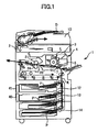
- the image formation apparatus 1 includes a document reading unit 2 that optically reads image information of a document D, an exposure unit 3 that irradiates an exposure light L to a photo conductor drum 5 based on the image information read by the document reading unit 2, an imaging unit 4 that forms a toner image on the photo conductor drum 5, an imprint unit 7 that imprints the toner image formed on the photo conductor drum 5 to a recording medium P, a document conveyance unit (ADF) 10 that conveys the document D to the document reading unit 2, feed units 12, 13, and 14 that store recording media P such as sheets of imprint paper, a fixing apparatus 20 that fixes the toner image to the recording medium P, a fixing roller 21 that is installed in the fixing apparatus 20, a pressurization roller 24 that is installed in the fixing apparatus 20, a main power supply 40 that supplies power to the fixing apparatus 20 and the like, and a power storage apparatus 41 that supplies auxiliary power to the fixing apparatus 20.
- ADF document conveyance unit
- the document D is conveyed in the direction of an arrow in Fig. 1 by the conveyance roller of the document conveyance unit 10 from a document stand, and passes on the top of the document reading unit 2.
- the document reading unit 2 optically reads image information of the document D.
- the optical image information read by the document reading unit 2 is converted into an electrical signal, and is provided to the exposure unit 3 (write-in unit).
- the exposure unit 3 emits the exposure light L, such as a laser beam, based on the electrical signal representing the image information, the exposure light L being emitted to the photo conductor drum 5 of the imaging unit 4.
- the photo conductor drum 5 rotates clockwise as shown in Fig. 1, and the toner image corresponding to the image information is formed on the photo conductor drum 5 through predetermined imaging processes (an electrification process, an exposure process, a development process, and the like).
- the imprint unit 7 imprints the toner image formed on the photo conductor drum 5 on the recording medium P conveyed by the resist roller.
- one of the feed units 12, 13, and 14 is chosen either automatically or manually.
- the feed unit 12 is assumed as being chosen.
- the top sheet of the recording medium P stored by the feed unit 12 is conveyed toward the position of a conveyance path K.
- the recording medium P passes the conveyance path K, and arrives at the position of a resist roller. Then, the recording medium P that arrives at the position of the resist roller waits for a proper timing such that the timing and position match with the toner image formed on the photo conductor drum 5, and travels again toward the imprint unit 7.
- the recording medium P that reaches the fixing apparatus 20 is fed between the fixing roller 21 and the pressurization roller 24, and the toner image is fixed by heat received from the fixing roller 21 and pressure received from both fixing roller 21 and pressurization roller 24.
- the recording medium P, on which the image is fixed is sent out from between the fixing roller 21 and the pressurization roller 24 and is discharged from the image formation apparatus 1.
- the fixing apparatus 20 includes a thermistor 37, a separation nail 38, and a guide board 35 in addition to the fixing roller 21, the pressurization roller 24.
- the fixing roller 21 is constituted by a thin-walled cylinder that rotates in the direction of an arrow shown in Fig. 2, and two heaters 22 and 23 that serve as heating members and are fixed inside the thin-walled cylinder.
- the surface of the thin-walled cylinder of the fixing roller 21 is fluorocarbon-resin processed such that the mold-release characteristic of toner T is obtained.
- the heaters 22 and 23 of the fixing roller 21 are cylindrical heaters, each of which has a heating wire inside, with both ends being fixed to side plates of the fixing apparatus 20.
- the heaters 22 and 23, to which electric power is provided, apply heat to the thin-walled cylinder, which heat is then applied to the toner T on the recording medium P from the surface of the thin-walled cylinder.
- the main power supply 40 supplies power to the heater 22 (as indicated by a dotted line arrow Y1), and the power storage apparatus 41 supplies power to the heater 23 (as indicated by a dotted line arrow Y2). Further details are described below.
- the thermistor 37 is provided so as to contact the surface of the fixing roller 21 such that the temperature of the surface of the fixing roller 21 is measured. Magnitudes of power provided from the main power supply 40 and the power storage apparatus 41 are adjusted based on the roller surface temperature measured by the thermistor 37.
- the separation nail 38 is arranged rocking-free, touching the surface of the fixing roller 21.
- the tip of the separation nail 38 touches the surface of the fixing roller 21 such that winding (coiling) of the recording medium P around the fixing roller 21 along with rotation of the fixing roller 21 is prevented from occurring, the recording medium P being sent out from between the fixing roller 21 and the pressurization roller 24.
- the pressurization roller 24 that contacts and pressures the fixing roller 21 (through a pressurization mechanism that is not illustrated) is structured by a core metal, and two or more elastic layers formed around the perimeter of the core metal through an adhesion layer.
- the elastic layers of the pressurization roller 24 are 1 through 10 mm thick, and are made of a fluororubber, silicone rubber, foaming silicone rubber, etc.
- the mold release layer is made of poly-imide, polyether imide, PES (polyether sulphide), PFA (4 fluoride ethylene perfuloro arkyl vinyl ether copolymer resin), etc.
- guide boards 35 are arranged on the entrance and the exit sides of the nip constituted by the fixing roller 21 and the pressurization roller 24 such that the recording medium P is properly guided for proper conveyance.
- the guide boards 35 are fixed to the side plate of the fixing apparatus 20.
- the fixing apparatus 20 as described above operates as follows.
- the main power supply 40 and the power storage apparatus 41 of the image formation apparatus 1 start supplying power to the heaters 22 and 23, respectively, of the fixing roller 21.
- the main power supply 40 supplies power to the heater 22, the power being based on the rated commercial main power supplied from a socket that is outside of the image formation apparatus 1, and the power storage apparatus 41 discharges and supplies power to the heater 23.
- the surface of the fixing roller 21 reaches a desired temperature (for example, 180 degrees C) in a short time, and the image formation apparatus 1 becomes operational.
- the fixing roller 21 and the pressurization roller 24 start rotating, being driven by a drive unit (not illustrated) in the directions of the arrows in Fig. 2.
- the imaging processes as described above are performed such that the recording medium P carrying the toner image T is guided by the guide boards 35, the recording medium P carrying the toner image T is fed between the fixing roller 21 and the pressurization roller 24 (movement in the direction of arrow Y10), the toner image T is fixed to the recording medium P by the heat received from the fixing roller 21 and the pressure received from both fixing roller 21 and pressurization roller 24, and the recording medium P is discharged from between the fixing roller 21 and the pressurization rollers 24 (movement in the direction of arrow Y11).
- the power storage apparatus 41 supplies power to the heater 23.
- the power consumption increases as compared with the time when the scanning operation is not performed, and the power storage apparatus 41 supplies power to the heater 23.
- the power storage apparatus 41 also supplies power to the heater 23.
- the power storage apparatus 41 also supplies power to the heater 23. In this manner, insufficiency of the power provided to the fixing apparatus 20 from the main power supply 40 is supplemented by discharge power of the power storage apparatus 41.
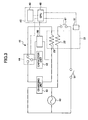
- the power storage apparatus 41 includes a capacitor unit 42 (cell unit), to which power is charged and from which power is discharged, a charging unit 43 configured to charge the capacitor unit 42, a switching unit 44 configured to switch between charging and discharging states of the capacitor unit 42, a voltmeter 50 serving as a voltage detection unit configured to detect the voltage of the capacitor unit 42, and a main power switch 51.
- the capacitor unit 42 of the power storage apparatus 41 an electric double layer capacitor, a nickel-cadmium battery, etc., can be used.
- the switching unit 44 When the switching unit 44 is turned on to the discharging side as illustrated in Fig. 3, the capacitor unit 42 discharges and supplies power to the heater 23.
- the charging unit 43 charges the capacitor unit 42, the charging unit 43 rectifying the AC power provided from the main power supply 40 into DC power.
- the change of the switching unit 44 is performed based on a change signal sent from a CPU 48 based on a predetermined control program stored in a memory of a control unit 45.
- the switching unit 44 may be configured by an FET, etc., such that the capacitor unit 42, which is a secondary heater, discharges and provides the power to the heater 23.
- control unit 45 controls the magnitude of the discharging power based on detection information of the thermistor 37. Further, the power storage apparatus 41 is charged at constant current or constant power. That is, the power storage apparatus 41 is controlled so that constant-current charging or constant power charging is carried out.
- the CPU 48 of the control unit 45 receives information concerning the voltage of the capacitor unit 42 from the voltmeter 50, and information concerning time from a timer 49, the timer 49 serving as a time detection unit.
- the CPU 48, the voltmeter 50 and the timer 49 serve as a degradation detection unit to detect degradation of the capacitor unit 42 by detecting that the power stored by the capacitor unit 42 falls below a predetermined value at a predetermined voltage.
- the main power supply 40 is connected to the power storage apparatus 41, the heater 22 that serves as the main heater, the main power switch 51, a control switch 47, and other loads (not illustrated) of the image formation apparatus 1.
- the main power switch 51 When the main power switch 51 is closed, the power supply to the main heater 22, the charge of the power storage apparatus 41, and the like become possible.
- the power supply to the heater 22 and the charge of the power storage apparatus 41 are performed based on a signal supplied by the control unit 45 based on the predetermined control program stored in the memory of the control unit 45. That is, when the control switch 47 is closed, the power is supplied to the heater 22. Further, when the switching unit 44 of the power storage apparatus 41 is connected to the charging unit 43, the power storage apparatus 41 is charged.
- the discharge power amount that the power storage apparatus 41 discharges is detected. Specifically, at the time of discharge, a time (discharge time), during which the voltage (discharging voltage) that remains in the capacitor unit 42 drops from a first discharging voltage (for example, 30V) to a second discharging voltage (for example, 20V) is measured using the voltmeter 50 and the timer 49. Since a constant-current charge or constant-resistance discharge is carried out, in the case that the first discharging voltage (discharge starting voltage) is the same (under the condition of the same voltage), the shorter the measured discharge time is, the smaller the discharge power amount is.
- the control unit 45 determines that the capacitor unit 42 is degraded. If the capacitor unit 42 is degraded, in comparison with the early stages of the service life, the discharge time becomes shorter. The discharge power that the capacitor unit 42 can provide to the heater 23 decreases, and the desired heating effect cannot be obtained. Further, if the capacitor unit 42 is degraded, compared with the early stages of the service life, the charge time become shorter. Therefore, the charge power (stored power) that is charged to the capacitor unit 42 decreases.
- control unit 45 finally determines the degradation of the capacitor unit 42 after carrying out the detection of the discharge time being below the predetermined value two or more times. In this manner, incorrect detection of the degradation state can be prevented from occurring.
- determination of the degradation state of the capacitor unit 42 by the control unit 45 is desirably carried out in consideration of an operating environment of the power storage apparatus 41. For example, when the power storage apparatus 41 is used under a high temperature environment and the discharge time is short, based on predetermined compensation data, the detected discharge time is compensated for and converted to a normal temperature environment. In this manner, the shortening of the discharge time due to the environment can be separated from what is due to degradation. In addition, the information concerning the operating environment is obtained by a thermometer, a hygrometer, and the like.
- setting values concerning charging/discharging are adjusted such that the discharge power amount is increased, based on degradation detection of the capacitor unit 42, the detection being carried out by the CPU 48, the timer 49, and the voltage meter 50 serving as the degradation detection unit.
- the CPU 48 the CPU 48, the timer 49, and the voltage meter 50 serving as the degradation detection unit.
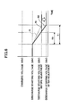
- Fig. 4 Reference is made to Fig. 4.
- a predetermined discharge starting voltage (discharge permission voltage) is adjusted to 33V from 30V.
- Fig. 4 gives a graph that shows change of the discharge time when adjusting the discharge starting voltage based on the degradation detection.
- the horizontal axis shows the time (detected by the timer 49), and the vertical axis shows the discharging voltage (which is in agreement with the charging voltage, and detected by the voltmeter 50) of the capacitor unit 42.
- a dashed line S shows the discharge property of the capacitor unit 42 in the early stages of the service life of the capacitor unit 42
- a solid line R1 shows the discharge property of the capacitor unit 42 that is degraded before adjusting the discharge starting voltage
- a solid line R2 shows the discharge property of the degraded capacitor unit 42 after adjusting discharge starting voltage.
- the "discharge starting voltage” is a voltage at which the discharge from the capacitor unit 42 is enabled, and it is a value set up for controlling purposes. That is, when the charging voltage of the capacitor unit 42 has not reached the discharge starting voltage, the capacitor unit 42 does not supply the discharge power to the heater 23. In other words, when the voltmeter 50 detects that the charging voltage of the capacitor unit 42 becomes greater than the discharge starting voltage, the switching unit 44 can be turned on to the discharging side.
- the charging voltage in Fig. 4 is a "target charge voltage" (the charging voltage of the capacitor unit 42 targeted when charging), and is a value set up for controlling purposes. That is, when there are no instructions from the control unit 45 to start discharging, and when the charging voltage exceeds the discharge starting voltage, the capacitor unit 42 is charged until the charging voltage reaches the target charge voltage.
- the "discharge stopping voltage” is a voltage at which the discharge from the capacitor unit 42 is stopped, and is a value set up for controlling purposes. That is, the capacitor unit 42 does not have to stop supplying the discharged power to the heater 23 while the discharging voltage of the capacitor unit 42 has not reached the discharge stopping voltage. Specifically, when the voltmeter 50 detects that the discharging voltage of the capacitor unit 42 is below the discharge stopping voltage, the switching unit 44 turns off the connection to the heater 23.
- the dashed line S in Fig. 4 shows the case wherein the discharge starting voltage is set at 30V, and the discharge time is a period from when the discharging voltage is equal to the discharge starting voltage (30 V) until the discharging voltage becomes the discharge stopping voltage (20 V), which represents the case of the early stages of the service life of the capacitor unit 42, and is expressed by T1.
- the discharge power amount at this time is sufficient to supply the power to the heater 23 of the fixing roller 21.
- the discharge time becomes T2, which is less than T1.
- the discharge power amount at this time is insufficient to properly supply the power to the heater 23 of the fixing roller 21.
- the control unit 45 (serving as an adjustment unit) raises the setting value of the discharge starting voltage from 30 V to 33 V (in the direction indicated by a white arrow in Fig. 4). Then, as shown by the solid line R2, the discharge time from 33 V to 20 V becomes equal to the early stages discharge time T1. The discharge power amount at this time becomes almost equal to the initial available power amount, i.e., is sufficient to supply the power to the heater 23.
- the setting value of the discharge starting voltage after adjustment is arranged to be no greater than the withstand voltage (the maximum voltage to be used) of the capacitor unit 42. Accordingly, reliable operation of the power storage apparatus 41 is ensured.
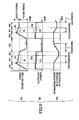
- Fig. 5 gives graphs showing state transitions of the fixing apparatus 20, the power storage apparatus 41, and the main power supply 40 when the image formation apparatus 1 of Embodiment 1 carries out image formation.
- the capacitor unit 42 of the power storage apparatus 41 is assumed be in a degradation state.
- a time change of the fixing temperature of the surface of the fixing roller 21 detected by the thermistor 37 is shown.
- a solid line M shows the fixing temperature change in the case where the discharge starting voltage is adjusted for degradation
- a dashed line N shows the fixing temperature change in the case where the adjustment is not performed.
- a time change of the supply power of the main power supply 40 and the power storage apparatus 41 is shown.
- a solid line Q1 shows the supply power change of the main power supply 40 to the image formation apparatus 1 (i.e., to all the loads including but not limited to the heater 22)
- a dashed line Q2 shows the supply power change to the heaters 22 and 23 from the main power supply 40 and the power storage apparatus 41, respectively (note that this is the total of the supply power to the heaters 22 and 23).
- time W0 is a preparation time, i.e., from the time when the image formation apparatus 1 is started after a state where the main power switch 51 is turned off for a long time.
- Time W1 is time wherein scanning of the document D by the document reading unit 2 and image formation are carried out.
- Time W2 is time wherein image formation is carried out based on the image information provided by the document reading unit 2 during the time W1. During the time W2, the document reading unit 2 does not perform scanning.
- Time W3 is time during which the image formation apparatus 1 is in the standby mode without performing image formation, while the main power switch 51 is kept turned on following the time W2.
- time W0' is time during which the image formation apparatus 1 is preparing for operation from the standby state.
- Time W1' is time during which scanning of the document D by the document reading unit 2 and image formation are carried out.
- Time W2' is time during which image formation is carried out without performing the scan by the document reading unit 2.
- the power storage apparatus 41 If the power storage apparatus 41 is degraded, unless the discharge starting voltage is adjusted as explained above with reference to Fig. 4, the power storage apparatus 41 cannot provide sufficient power during the times W1 and W1' for supplementing the power from the main power supply 40 to the fixing apparatus 20, with the operation of the document reading unit 2 ongoing, as shown by the dashed lines N at (A) of Fig. 5. For this reason, in the times W1 and W1', poor fixing due to temperature drop of the fixing roller 21 occurs. In addition, a dashed line that is parallel to the horizontal axis at (A) of Fig. 5 represents the minimum fixing temperature, below which poor fixing is produced.
- the power storage apparatus 41 is capable of supplementing the power from the main power supply 40 to the fixing apparatus 20 during the times W1 and W1'. That is, during the times W1 and W1', as shown at (C) of Fig. 5, the power storage apparatus 41 discharges, and as shown by the dashed lines Q2 at (B) of Fig. 5, the power supplied to the fixing apparatus 20 is increased. In this manner, during the times W1 and W1', the temperature dropping below the minimum fixing temperature can be prevented from occurring, and satisfactory fixing is obtained.
- the degradation state of the power storage apparatus 41 can be reliably managed. Furthermore, when the power storage apparatus 41 is degraded, the shortened discharge time is restored to the early stages level by adjusting the discharge starting voltage. The service life of the power storage apparatus 41 is prolonged by suppressing the discharge power drop and maintaining the performance of the power storage apparatus 41, even if the power storage apparatus 41 is degraded.
- the degradation of the capacitor unit 42 can also be determined by detecting a voltage change of the capacitor unit 42 in a fixed time. That is, since the discharging voltage drop per unit time when discharging becomes greater when the capacitor unit 42 is degraded as compared with the early stages, an amount of voltage drop (discharging voltage change) per unit time represents the degree of the degradation.
- the discharging voltage change becomes greater than a predetermined value, it is determined that the capacitor 42 is degraded, and the setting value of the discharge starting voltage is adjusted upward as described above. This variation provides the same effect as Embodiment 1.
- the change of the discharge power amount of the power storage apparatus 41 when discharging is detected, and the degradation of the capacitor unit 42 is determined based on this.
- a different method is possible. That is, a change of the charge power amount of the power storage apparatus 41 when charging may be detected, and the degradation of the capacitor unit 42 may be determined based on this. Furthermore, the changes of both charge amount and discharge amount may be detected, and the degradation of the capacitor unit 42 may be determined based on the changes. Since the power storage apparatus 41 is charged by a constant current control, if the capacitor unit 42 is degraded, the charge time becomes short, and a charged power amount declines.
- Embodiment 2 of the present invention is described in detail with reference to Fig. 6.
- Fig. 6 is a graph that shows an adjustment control that is carried out when the power storage apparatus 41 is degraded according to Embodiment 2.
- the discharge stopping voltage is adjusted according to Embodiment 2, which is different from Embodiment 1 wherein the discharge starting voltage is adjusted.
- Fig. 6 is a graph that shows a change of the discharge time when adjusting the discharge stopping voltage based on the same degradation detection carried out by the same degradation detection unit as Embodiment 1, the degradation detection unit being constituted by the CPU 48, the timer 49.
- the horizontal axis shows the time and the vertical axis shows the voltage of the capacitor unit 42.
- a dashed line S shows the discharge property of the capacitor unit 42 in the early stages of the service life
- a solid line R1 shows the discharge property of the capacitor unit 42 that is degraded before the discharge stopping voltage is adjusted
- a solid line R2 shows the discharge property of the degraded capacitor unit 42 after the discharge stopping voltage is adjusted.
- the discharge stopping voltage is set at 20 V, and the discharge time from the discharge starting voltage (30 V) to the discharge stopping voltage 20 V is T1.
- the discharge power amount at this time is sufficient to provide power to the heater 23 of the fixing roller 21.
- the capacitor unit 42 With the passage of time, the capacitor unit 42 is degraded, which is detected as described above. At this time, the discharge time becomes shorter as shown by T2 (refer to the solid line R1). The discharge power amount at this time is insufficient to provide power to the heater 23 of the fixing roller 21.
- the setting value of the discharge stopping voltage is adjusted downward to 18 V from 20 V by the control unit 45 as indicated by a white arrow in Fig. 6. Accordingly, as shown by the solid line R2, the discharge time from 30 V to the adjusted 18 V is made as long as T1. The discharge power amount at this time becomes almost equivalent to that of the early stages, and sufficient power can be supplied to the heater 23.
- the setting value of the discharge stopping voltage is adjusted to be no less than the reverse voltage generating voltage (i.e., the minimum voltage to be used) of the capacitor unit 42. In this manner, the power storage apparatus 41 being reliable is offered.
- the degradation state of the power storage apparatus 41 can be reliably managed. Furthermore, when the power storage apparatus 41 is degraded, the shortened discharge time is restored to that of the early stages by adjusting the discharge stopping voltage. In this manner, the service life of the power storage apparatus 41 is prolonged with the discharge power drop being suppressed, and the performance of power storage apparatus 41 being maintained, even if the power storage apparatus 41 is degraded.
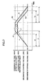
- Embodiment 3 of the present invention is described in detail with reference to Fig. 7.
- Fig. 7 is a graph that shows an adjustment control of Embodiment 3, which adjustment control is carried out when the power storage apparatus 41 is degraded.
- Embodiment 3 differs from Embodiments 1 and 2 in that Embodiment 3 adjusts a target charge voltage when the capacitor unit 42 of the power storage apparatus 41 is degraded, and that degradation of the capacitor unit 42 is also detected when charging in addition to when discharging.
- Fig. 7 is a graph that shows changes of the charge time and the discharge time when the target charge voltage is adjusted based on the degradation state of the capacitor unit 42.
- the horizontal axis shows the time and the vertical axis shows the charging voltage and discharging voltage of the capacitor unit 42.
- a dashed line s shows the charging property of the capacitor unit 42 in the early stages of the service life
- a solid line r1 shows the charging property of the capacitor unit 42 that is degraded before adjusting the target charge voltage
- a solid line r2 shows the charging property of the degraded capacitor unit 42 after adjusting the target charge voltage
- a dashed line S shows the discharging property of the capacitor unit 42 in the early stages
- a solid line R1 shows the discharging property of the capacitor unit 42 that is degraded before adjusting the target charge voltage
- a solid line R2 shows the discharging property of the degraded capacitor unit 42 after adjusting the target charge voltage.
- the target charge voltage is set at 40 V, and the charge time required to raise the voltage from the discharge stopping voltage (20 V) to the target charge voltage (40 V) is expressed by t1.
- the charge power amount at this time is sufficient as the amount of charge to be stored in the capacitor unit 42.
- the target charge voltage is set at 40 V, and the discharge time during which the voltage drops from the target charge voltage 40 V to the discharge stopping voltage 20 V is expressed by T1.
- the discharge power amount at this time is sufficient to supply power to the heater 23 of the fixing roller 21.
- the degradation of the capacitor unit 42 is detected based on the charge time being shortened at the time of charging, and the discharge time being shortened at the time of discharging.
- the charge time t2 from the discharge stopping voltage (20V) to the target charge voltage (40V) becomes shorter than t1.
- the charged power amount at this time is insufficient as the amount of charge stored in the capacitor unit 42.
- the discharge time from the target charge voltage (40V) to the discharge stopping voltage (20V), which discharge time is expressed by T2 becomes shorter than T1.
- the discharge power amount at this time is insufficient to supply the power to the heater 23 of the fixing roller 21.
- the control unit 45 raises the setting value of the target charge voltage from 40 V to 43 V (the adjustment in the direction of the white arrow in Fig. 7). That is, as shown by the solid line r2, the charge time from the discharge stopping voltage 20 V to the adjusted target charge voltage 43 V becomes equivalent to t1, which is the charge time at the early stages. The charge power amount at this time becomes almost equivalent to that of the early stages, and is sufficient as the amount of charge stored in the capacitor unit 42.
- the discharge time from the target charge voltage after adjustment, i.e., 43 V, to the discharge stopping voltage 20 V becomes equivalent to T1, which is the discharge time of the early stages.
- the discharge power amount at this time is almost equivalent to that of the early stages, and is sufficient to supply the power to the heater 23.
- the setting value of the target charge voltage is adjusted to be no greater than the withstand voltage (the maximum voltage to be used) of the capacitor unit 42. In this manner, the power storage apparatus 41 offered provides high reliability.
- the drop of the charge power amount and the drop of the discharge power amount accompanying the short charge time and discharge time, respectively, are detected by the detection unit (which includes the CPU 48, the timer 49, and the voltage meter 50), and the degradation state of the power storage apparatus 41 is properly managed. Furthermore, when the power storage apparatus 41 is degraded, the shortened charge time and the shortened discharge time are restored to those at the early stages of the service life of the power storage apparatus 41 by adjusting the target charge voltage. In this manner, even when the capacitor unit 42 is degraded, the service life of the power storage apparatus 41 is prolonged, the charge power amount drop and the discharge power amount drop are prevented from occurring, and the performance of the power storage apparatus 41 is maintained.
- the detection unit which includes the CPU 48, the timer 49, and the voltage meter 50
- the control unit 45 controls based on the control program such that the degradation detection unit including the CPU 48, the timer 49, and the voltage meter 50 detects the degradation of the capacitor unit 42, and adjusts the setting values of such as the discharge starting voltage so that the discharge power amount is adjusted.
- the adjustment can be manually performed. That is, when the degradation detection unit (the CPU 48, the timer 49, and the voltage meter 50) detects the degradation of the capacitor unit 42, a message to that effect is displayed on a display (not illustrated) of the image formation apparatus 1 such that a person, e.g., a service-person, is notified of the fact.
- the service-person adjusts the setting value of the discharge starting voltage of the power storage apparatus 41 by manually operating (external input) an operations unit (not illustrated) according to the displayed message.
- the degradation of the capacitor unit 42 is detected by the degradation detection unit (the CPU 48, the timer 49, and the voltage meter 50 serving as the degradation detection unit), and the setting value of the discharge starting voltage, etc., is adjusted such that the shortened discharge time is restored. If the degradation of the capacitor unit 42 progresses further, and if the discharge time cannot be restored to that of the early stages of the service life by adjusting the discharge starting voltage, etc., the number of sheets of the recording medium P that are conveyed per unit time (CPM) to the fixing apparatus 20 can be controlled downward.
- the degradation detection unit the CPU 48, the timer 49, and the voltage meter 50 serving as the degradation detection unit
- an interval of sheet conveyance can be controlled while keeping the conveyance speed; or alternatively, the conveyance speed can be reduced while keeping the sheet conveyance interval. In this manner, the heat consumption (dissipation) of the fixing roller 21 per unit time is reduced, and the degraded power storage apparatus 41 can continue to provide services.
- Embodiments 1, 2 and 3 describe the power storage apparatus 41 serving as an auxiliary power supply at the time of starting the image formation apparatus 1, and when otherwise required.
- the present invention is not limited to this, but can be applied to any power storage apparatus that supplies power to any electrical load, providing the same highly efficient and long-life power storage apparatus as embodied as above.
- the present invention can be suitably modified within the limits of the technical thought of the present invention, besides as embodied above and as suggested above.
- the present invention is not limited to Embodiments described above.
- the structure, the number of members, the position, the form, etc., as described above are not limited to what are described as Embodiments, but the present invention can be implemented with a suitable structure, a suitable number, a suitable position, a suitable form, etc.
Landscapes
- Engineering & Computer Science (AREA)
- Power Engineering (AREA)
- Microelectronics & Electronic Packaging (AREA)
- Physics & Mathematics (AREA)
- General Physics & Mathematics (AREA)
- Fixing For Electrophotography (AREA)
- Control Or Security For Electrophotography (AREA)
- Charge And Discharge Circuits For Batteries Or The Like (AREA)
- Accessory Devices And Overall Control Thereof (AREA)
- Dc-Dc Converters (AREA)
- Secondary Cells (AREA)
Applications Claiming Priority (2)
| Application Number | Priority Date | Filing Date | Title |
|---|---|---|---|
| JP2004027796A JP2005219273A (ja) | 2004-02-04 | 2004-02-04 | 蓄電装置、定着装置、及び、画像形成装置 |
| JP2004027796 | 2004-02-04 |
Publications (3)
| Publication Number | Publication Date |
|---|---|
| EP1562274A2 true EP1562274A2 (de) | 2005-08-10 |
| EP1562274A3 EP1562274A3 (de) | 2011-03-09 |
| EP1562274B1 EP1562274B1 (de) | 2015-08-05 |
Family
ID=34675492
Family Applications (1)
| Application Number | Title | Priority Date | Filing Date |
|---|---|---|---|
| EP05250560.9A Expired - Lifetime EP1562274B1 (de) | 2004-02-04 | 2005-02-02 | Energiespeichervorrichtung, Fixiergerät und Bilderzeugungsgerät |
Country Status (3)
| Country | Link |
|---|---|
| US (1) | US7603049B2 (de) |
| EP (1) | EP1562274B1 (de) |
| JP (1) | JP2005219273A (de) |
Cited By (1)
| Publication number | Priority date | Publication date | Assignee | Title |
|---|---|---|---|---|
| EP3576250A4 (de) * | 2017-01-27 | 2019-12-04 | Panasonic Intellectual Property Management Co., Ltd. | Fahrzeugmontierte notstromversorgungsvorrichtung |
Families Citing this family (49)
| Publication number | Priority date | Publication date | Assignee | Title |
|---|---|---|---|---|
| JP2005219273A (ja) | 2004-02-04 | 2005-08-18 | Ricoh Co Ltd | 蓄電装置、定着装置、及び、画像形成装置 |
| JP2006154010A (ja) * | 2004-11-26 | 2006-06-15 | Ricoh Co Ltd | 定着装置及び画像形成装置 |
| JP4866031B2 (ja) * | 2005-04-22 | 2012-02-01 | 株式会社リコー | 画像形成装置 |
| JP2007035606A (ja) * | 2005-07-29 | 2007-02-08 | Ricoh Co Ltd | 加熱装置、定着装置及び画像形成装置 |
| US7933529B2 (en) * | 2005-08-30 | 2011-04-26 | Ricoh Company, Ltd. | Image forming apparatus, method for controlling image forming apparatus, fixing apparatus |
| JP4943100B2 (ja) * | 2005-09-16 | 2012-05-30 | 株式会社リコー | 画像形成装置 |
| US8315534B2 (en) * | 2005-11-01 | 2012-11-20 | Ricoh Company, Ltd. | Image forming device to supply DC power to a load from both a main power supply device and a capacitor supply device |
| US7629780B2 (en) * | 2005-11-21 | 2009-12-08 | Ricoh Company, Ltd. | Power supply unit and printing apparatus with a supplemental power supply unit |
| JP4803583B2 (ja) * | 2006-02-03 | 2011-10-26 | 株式会社リコー | 電源装置および画像形成装置 |
| JP4824396B2 (ja) | 2005-12-19 | 2011-11-30 | 株式会社リコー | 画像形成装置 |
| JP4942148B2 (ja) * | 2006-02-24 | 2012-05-30 | 株式会社リコー | 画像形成装置 |
| JP4793920B2 (ja) | 2006-02-24 | 2011-10-12 | 株式会社リコー | 電源装置および画像形成装置 |
| JP4577781B2 (ja) | 2006-03-03 | 2010-11-10 | 株式会社リコー | 電源装置および画像形成装置 |
| JP4956082B2 (ja) * | 2006-07-31 | 2012-06-20 | 京セラドキュメントソリュ−ションズ株式会社 | 画像形成装置 |
| JP5259073B2 (ja) * | 2006-10-31 | 2013-08-07 | 京セラドキュメントソリューションズ株式会社 | 画像形成装置 |
| JP4917903B2 (ja) * | 2007-01-31 | 2012-04-18 | 株式会社リコー | 加熱装置、定着装置、加熱部材の温度制御方法及び画像形成装置 |
| KR101460537B1 (ko) * | 2007-02-01 | 2014-11-12 | 삼성전자 주식회사 | 화상형성장치 및 그 제어방법 |
| US7546052B2 (en) * | 2007-03-20 | 2009-06-09 | Kabushiki Kaisha Toshiba | Image forming apparatus and method of controlling charging the apparatus to reduce warm up time |
| JP2011090232A (ja) * | 2009-10-26 | 2011-05-06 | Ricoh Co Ltd | 加熱装置、定着装置及び画像形成装置 |
| JP5648291B2 (ja) * | 2010-02-01 | 2015-01-07 | 株式会社リコー | 光沢付与装置および画像形成装置 |
| JP2011170267A (ja) * | 2010-02-22 | 2011-09-01 | Ricoh Co Ltd | 画像形成装置 |
| JP5482310B2 (ja) * | 2010-03-09 | 2014-05-07 | 株式会社リコー | 定着装置及び画像形成装置 |
| JP5640473B2 (ja) | 2010-06-04 | 2014-12-17 | 株式会社リコー | 定着装置及び画像形成装置 |
| JP5552939B2 (ja) | 2010-07-27 | 2014-07-16 | 株式会社リコー | ベルト走行装置、定着装置及び画像形成装置 |
| JP5625865B2 (ja) | 2010-12-16 | 2014-11-19 | 株式会社リコー | 定着装置及び画像形成装置 |
| US8693934B2 (en) | 2010-12-17 | 2014-04-08 | Ricoh Company, Ltd. | Fixing device and image forming apparatus incorporating same |
| JP5589820B2 (ja) | 2010-12-17 | 2014-09-17 | 株式会社リコー | 定着装置及び画像形成装置 |
| JP5640750B2 (ja) | 2011-01-07 | 2014-12-17 | 株式会社リコー | 定着装置、画像形成装置、定着制御方法 |
| JP5879988B2 (ja) | 2011-01-11 | 2016-03-08 | 株式会社リコー | 定着装置及び画像形成装置 |
| JP5825545B2 (ja) | 2011-01-11 | 2015-12-02 | 株式会社リコー | 定着装置および画像形成装置 |
| JP5699656B2 (ja) | 2011-02-08 | 2015-04-15 | 株式会社リコー | 光沢付与装置及び定着装置、画像形成装置 |
| JP5741905B2 (ja) * | 2011-02-16 | 2015-07-01 | 株式会社リコー | 画像形成装置 |
| JP2012181337A (ja) | 2011-03-01 | 2012-09-20 | Ricoh Co Ltd | 光沢付与装置及びこれを用いた画像形成装置 |
| JP2012185295A (ja) | 2011-03-04 | 2012-09-27 | Ricoh Co Ltd | 定着装置および画像形成装置 |
| JP5870569B2 (ja) | 2011-03-09 | 2016-03-01 | 株式会社リコー | 定着装置及び画像形成装置 |
| JP5768507B2 (ja) | 2011-03-17 | 2015-08-26 | 株式会社リコー | 定着装置および画像形成装置 |
| JP5708084B2 (ja) | 2011-03-17 | 2015-04-30 | 株式会社リコー | 定着装置、及び、これを備える画像形成装置 |
| JP5822061B2 (ja) | 2011-06-21 | 2015-11-24 | 株式会社リコー | 光沢付与装置、画像形成装置、カラー画像形成装置 |
| JP2013003517A (ja) | 2011-06-21 | 2013-01-07 | Ricoh Co Ltd | 光沢付与装置、定着装置、及び画像形成装置 |
| JP2013007801A (ja) | 2011-06-22 | 2013-01-10 | Ricoh Co Ltd | 光沢付与装置、及び画像形成装置 |
| JP5824903B2 (ja) | 2011-06-23 | 2015-12-02 | 株式会社リコー | 光沢付与装置および画像形成装置 |
| JP5831740B2 (ja) | 2011-06-30 | 2015-12-09 | 株式会社リコー | 定着装置、および画像形成装置 |
| JP5891764B2 (ja) | 2011-12-12 | 2016-03-23 | 株式会社リコー | 光沢付与装置および画像形成装置 |
| JP2013140214A (ja) | 2011-12-28 | 2013-07-18 | Ricoh Co Ltd | 画像形成装置 |
| JP5751428B2 (ja) | 2012-01-31 | 2015-07-22 | 株式会社リコー | 定着装置及び画像形成装置 |
| JP6209311B2 (ja) | 2012-02-09 | 2017-10-04 | 株式会社リコー | 定着装置及び画像形成装置 |
| JP6015176B2 (ja) | 2012-07-10 | 2016-10-26 | 株式会社リコー | 光沢付与装置、及び、画像形成装置 |
| US20150008896A1 (en) * | 2013-07-02 | 2015-01-08 | Experium Technologies, Llc | Constant resistance to constant current/constant power start-up |
| TWI798671B (zh) * | 2021-03-30 | 2023-04-11 | 力林科技股份有限公司 | 電源供應裝置及其放電方法 |
Citations (1)
| Publication number | Priority date | Publication date | Assignee | Title |
|---|---|---|---|---|
| US6459242B1 (en) | 2001-09-06 | 2002-10-01 | Hewlett-Packard Company | Methods and systems for indicating a charge state of a charge storage device |
Family Cites Families (11)
| Publication number | Priority date | Publication date | Assignee | Title |
|---|---|---|---|---|
| JP3545834B2 (ja) * | 1994-09-21 | 2004-07-21 | 株式会社リコー | 熱定着装置 |
| US5670915A (en) * | 1996-05-24 | 1997-09-23 | Microchip Technology Incorporated | Accurate RC oscillator having peak - to - peak voltage control |
| JPH09320785A (ja) * | 1996-05-29 | 1997-12-12 | Minolta Co Ltd | フラッシュ充電装置 |
| US6094051A (en) * | 1998-09-15 | 2000-07-25 | Alliedsignal Inc. | Apparatus and method for detecting memory effect in nickel cadmium batteries |
| JP4107539B2 (ja) | 1999-08-27 | 2008-06-25 | 株式会社リコー | 画像形成装置 |
| US6204634B1 (en) * | 2000-06-26 | 2001-03-20 | The Aerospace Corporation | Adaptive charging method for lithium-ion battery cells |
| US6542705B2 (en) * | 2000-09-29 | 2003-04-01 | Ricoh Company, Ltd. | Electrophotographic heating apparatus, system, and method |
| US6385412B1 (en) * | 2000-11-28 | 2002-05-07 | Toshiba Tec Kabushiki Kaisha | Image forming apparatus |
| JP3902565B2 (ja) * | 2002-05-31 | 2007-04-11 | 株式会社リコー | 定着装置および画像形成装置 |
| CN100527899C (zh) * | 2002-07-12 | 2009-08-12 | 株式会社理光 | 加热装置、辅助电力供给装置、辅助电力供给系统、定影装置及图像形成装置 |
| JP2005219273A (ja) | 2004-02-04 | 2005-08-18 | Ricoh Co Ltd | 蓄電装置、定着装置、及び、画像形成装置 |
-
2004
- 2004-02-04 JP JP2004027796A patent/JP2005219273A/ja active Pending
-
2005
- 2005-02-02 US US11/047,686 patent/US7603049B2/en not_active Expired - Fee Related
- 2005-02-02 EP EP05250560.9A patent/EP1562274B1/de not_active Expired - Lifetime
Patent Citations (1)
| Publication number | Priority date | Publication date | Assignee | Title |
|---|---|---|---|---|
| US6459242B1 (en) | 2001-09-06 | 2002-10-01 | Hewlett-Packard Company | Methods and systems for indicating a charge state of a charge storage device |
Cited By (1)
| Publication number | Priority date | Publication date | Assignee | Title |
|---|---|---|---|---|
| EP3576250A4 (de) * | 2017-01-27 | 2019-12-04 | Panasonic Intellectual Property Management Co., Ltd. | Fahrzeugmontierte notstromversorgungsvorrichtung |
Also Published As
| Publication number | Publication date |
|---|---|
| US7603049B2 (en) | 2009-10-13 |
| JP2005219273A (ja) | 2005-08-18 |
| US20050191078A1 (en) | 2005-09-01 |
| EP1562274A3 (de) | 2011-03-09 |
| EP1562274B1 (de) | 2015-08-05 |
Similar Documents
| Publication | Publication Date | Title |
|---|---|---|
| EP1562274B1 (de) | Energiespeichervorrichtung, Fixiergerät und Bilderzeugungsgerät | |
| US7212759B2 (en) | Heating device, fixing device and image forming apparatus | |
| US7609988B2 (en) | Heater, fixing unit and image forming apparatus having power supplied from chargeable auxiliary power supplying unit varied per unit time | |
| EP1542085B1 (de) | Heizvorrichtung mit haupt und neben Stromversorgungseinheit in einer Fixiervorrichtung für ein Bilderzeugungsgerät | |
| US8023126B2 (en) | Image forming apparatus with a chargeable capacitor | |
| US20060051121A1 (en) | Fixing device, image forming apparatus including the fixing device, and fixing method | |
| CN100590545C (zh) | 加热系统以及使用该加热系统的图像形成装置 | |
| US7583910B2 (en) | Image forming apparatus | |
| JP4824396B2 (ja) | 画像形成装置 | |
| JP2010117652A (ja) | 画像形成装置及びその制御方法 | |
| JP2003257590A (ja) | 加熱装置とそれを使用した定着装置及び画像形成装置 | |
| JP4429951B2 (ja) | 画像形成装置 | |
| JP2004117468A (ja) | 画像形成装置 | |
| JP4390142B2 (ja) | 画像形成装置 | |
| JP4944546B2 (ja) | 電気機器および画像形成装置 | |
| JP4532921B2 (ja) | 画像形成装置 | |
| JP5741905B2 (ja) | 画像形成装置 | |
| JP4462578B2 (ja) | 画像形成装置 | |
| JP4490130B2 (ja) | 画像形成装置 | |
| JP4944236B2 (ja) | 画像形成装置 | |
| JP4956082B2 (ja) | 画像形成装置 | |
| JP2008039922A (ja) | 画像形成装置 | |
| JP2008052099A (ja) | 画像形成装置 |
Legal Events
| Date | Code | Title | Description |
|---|---|---|---|
| PUAI | Public reference made under article 153(3) epc to a published international application that has entered the european phase |
Free format text: ORIGINAL CODE: 0009012 |
|
| 17P | Request for examination filed |
Effective date: 20050222 |
|
| AK | Designated contracting states |
Kind code of ref document: A2 Designated state(s): AT BE BG CH CY CZ DE DK EE ES FI FR GB GR HU IE IS IT LI LT LU MC NL PL PT RO SE SI SK TR |
|
| AX | Request for extension of the european patent |
Extension state: AL BA HR LV MK YU |
|
| PUAL | Search report despatched |
Free format text: ORIGINAL CODE: 0009013 |
|
| AK | Designated contracting states |
Kind code of ref document: A3 Designated state(s): AT BE BG CH CY CZ DE DK EE ES FI FR GB GR HU IE IS IT LI LT LU MC NL PL PT RO SE SI SK TR |
|
| AX | Request for extension of the european patent |
Extension state: AL BA HR LV MK YU |
|
| AKX | Designation fees paid |
Designated state(s): DE FR GB |
|
| 17Q | First examination report despatched |
Effective date: 20121008 |
|
| RIC1 | Information provided on ipc code assigned before grant |
Ipc: H02J 7/34 20060101AFI20140225BHEP Ipc: G03G 15/00 20060101ALI20140225BHEP |
|
| GRAP | Despatch of communication of intention to grant a patent |
Free format text: ORIGINAL CODE: EPIDOSNIGR1 |
|
| INTG | Intention to grant announced |
Effective date: 20141021 |
|
| GRAJ | Information related to disapproval of communication of intention to grant by the applicant or resumption of examination proceedings by the epo deleted |
Free format text: ORIGINAL CODE: EPIDOSDIGR1 |
|
| GRAP | Despatch of communication of intention to grant a patent |
Free format text: ORIGINAL CODE: EPIDOSNIGR1 |
|
| INTG | Intention to grant announced |
Effective date: 20150108 |
|
| INTG | Intention to grant announced |
Effective date: 20150114 |
|
| GRAS | Grant fee paid |
Free format text: ORIGINAL CODE: EPIDOSNIGR3 |
|
| RIN1 | Information on inventor provided before grant (corrected) |
Inventor name: KATO, YASUHISA Inventor name: TAKAGI, HIROMASA Inventor name: TSUKIOKA, YASUTADA Inventor name: OKAMOTO, MASAMI Inventor name: MATSUSAKA, SUSUMU Inventor name: KISHI, KAZUHITO Inventor name: AMITA, AKIYASU |
|
| GRAA | (expected) grant |
Free format text: ORIGINAL CODE: 0009210 |
|
| AK | Designated contracting states |
Kind code of ref document: B1 Designated state(s): DE FR GB |
|
| REG | Reference to a national code |
Ref country code: GB Ref legal event code: FG4D |
|
| REG | Reference to a national code |
Ref country code: DE Ref legal event code: R096 Ref document number: 602005047144 Country of ref document: DE |
|
| REG | Reference to a national code |
Ref country code: FR Ref legal event code: PLFP Year of fee payment: 12 |
|
| REG | Reference to a national code |
Ref country code: DE Ref legal event code: R097 Ref document number: 602005047144 Country of ref document: DE |
|
| PLBE | No opposition filed within time limit |
Free format text: ORIGINAL CODE: 0009261 |
|
| STAA | Information on the status of an ep patent application or granted ep patent |
Free format text: STATUS: NO OPPOSITION FILED WITHIN TIME LIMIT |
|
| 26N | No opposition filed |
Effective date: 20160509 |
|
| REG | Reference to a national code |
Ref country code: FR Ref legal event code: PLFP Year of fee payment: 13 |
|
| REG | Reference to a national code |
Ref country code: FR Ref legal event code: PLFP Year of fee payment: 14 |
|
| P01 | Opt-out of the competence of the unified patent court (upc) registered |
Effective date: 20230522 |
|
| PGFP | Annual fee paid to national office [announced via postgrant information from national office to epo] |
Ref country code: DE Payment date: 20240219 Year of fee payment: 20 Ref country code: GB Payment date: 20240219 Year of fee payment: 20 |
|
| PGFP | Annual fee paid to national office [announced via postgrant information from national office to epo] |
Ref country code: FR Payment date: 20240220 Year of fee payment: 20 |
|
| REG | Reference to a national code |
Ref country code: DE Ref legal event code: R071 Ref document number: 602005047144 Country of ref document: DE |
|
| REG | Reference to a national code |
Ref country code: GB Ref legal event code: PE20 Expiry date: 20250201 |
|
| PG25 | Lapsed in a contracting state [announced via postgrant information from national office to epo] |
Ref country code: GB Free format text: LAPSE BECAUSE OF EXPIRATION OF PROTECTION Effective date: 20250201 |