EP1562401A2 - Tonwiedergabegerät und Verfahren zur Tonwiedergabe - Google Patents
Tonwiedergabegerät und Verfahren zur Tonwiedergabe Download PDFInfo
- Publication number
- EP1562401A2 EP1562401A2 EP05250362A EP05250362A EP1562401A2 EP 1562401 A2 EP1562401 A2 EP 1562401A2 EP 05250362 A EP05250362 A EP 05250362A EP 05250362 A EP05250362 A EP 05250362A EP 1562401 A2 EP1562401 A2 EP 1562401A2
- Authority
- EP
- European Patent Office
- Prior art keywords
- sound
- signal
- frequency components
- listener
- reproduction
- Prior art date
- Legal status (The legal status is an assumption and is not a legal conclusion. Google has not performed a legal analysis and makes no representation as to the accuracy of the status listed.)
- Withdrawn
Links
Images


Classifications
-
- H—ELECTRICITY
- H04—ELECTRIC COMMUNICATION TECHNIQUE
- H04S—STEREOPHONIC SYSTEMS
- H04S1/00—Two-channel systems
- H04S1/002—Non-adaptive circuits, e.g. manually adjustable or static, for enhancing the sound image or the spatial distribution
-
- A—HUMAN NECESSITIES
- A01—AGRICULTURE; FORESTRY; ANIMAL HUSBANDRY; HUNTING; TRAPPING; FISHING
- A01G—HORTICULTURE; CULTIVATION OF VEGETABLES, FLOWERS, RICE, FRUIT, VINES, HOPS OR SEAWEED; FORESTRY; WATERING
- A01G7/00—Botany in general
- A01G7/06—Treatment of growing trees or plants, e.g. for preventing decay of wood, for tingeing flowers or wood, for prolonging the life of plants
-
- B—PERFORMING OPERATIONS; TRANSPORTING
- B65—CONVEYING; PACKING; STORING; HANDLING THIN OR FILAMENTARY MATERIAL
- B65D—CONTAINERS FOR STORAGE OR TRANSPORT OF ARTICLES OR MATERIALS, e.g. BAGS, BARRELS, BOTTLES, BOXES, CANS, CARTONS, CRATES, DRUMS, JARS, TANKS, HOPPERS, FORWARDING CONTAINERS; ACCESSORIES, CLOSURES, OR FITTINGS THEREFOR; PACKAGING ELEMENTS; PACKAGES
- B65D47/00—Closures with filling and discharging, or with discharging, devices
- B65D47/04—Closures with discharging devices other than pumps
- B65D47/043—Closures with discharging devices other than pumps with pouring baffles, e.g. for controlling the flow
-
- B—PERFORMING OPERATIONS; TRANSPORTING
- B65—CONVEYING; PACKING; STORING; HANDLING THIN OR FILAMENTARY MATERIAL
- B65D—CONTAINERS FOR STORAGE OR TRANSPORT OF ARTICLES OR MATERIALS, e.g. BAGS, BARRELS, BOTTLES, BOXES, CANS, CARTONS, CRATES, DRUMS, JARS, TANKS, HOPPERS, FORWARDING CONTAINERS; ACCESSORIES, CLOSURES, OR FITTINGS THEREFOR; PACKAGING ELEMENTS; PACKAGES
- B65D47/00—Closures with filling and discharging, or with discharging, devices
- B65D47/04—Closures with discharging devices other than pumps
- B65D47/06—Closures with discharging devices other than pumps with pouring spouts or tubes; with discharge nozzles or passages
-
- H—ELECTRICITY
- H04—ELECTRIC COMMUNICATION TECHNIQUE
- H04S—STEREOPHONIC SYSTEMS
- H04S1/00—Two-channel systems
- H04S1/002—Non-adaptive circuits, e.g. manually adjustable or static, for enhancing the sound image or the spatial distribution
- H04S1/005—For headphones
-
- H—ELECTRICITY
- H04—ELECTRIC COMMUNICATION TECHNIQUE
- H04S—STEREOPHONIC SYSTEMS
- H04S2420/00—Techniques used stereophonic systems covered by H04S but not provided for in its groups
- H04S2420/01—Enhancing the perception of the sound image or of the spatial distribution using head related transfer functions [HRTF's] or equivalents thereof, e.g. interaural time difference [ITD] or interaural level difference [ILD]
-
- H—ELECTRICITY
- H04—ELECTRIC COMMUNICATION TECHNIQUE
- H04S—STEREOPHONIC SYSTEMS
- H04S2420/00—Techniques used stereophonic systems covered by H04S but not provided for in its groups
- H04S2420/05—Application of the precedence or Haas effect, i.e. the effect of first wavefront, in order to improve sound-source localisation
Definitions
- the present invention relates to a sound reproduction apparatus capable of three-dimensional stereophonic sound reproduction and a sound reproduction method for use with the sound reproduction apparatus.
- a sound field reproduction system for reproducing a three-dimensional stereophonic sound field for example, a sound system for reproducing three-dimensional stereophonic sound using two speakers in front of and two speakers behind a listener, that is, a total of four speakers, is known.
- a three-dimensional sound reproduction system for reproducing a three-dimensional stereophonic sound field using two speakers has also been proposed.
- a sound signal that is radiated from a sound source, such as a musical instrument, and that arrives at the ears of the audience accompanied with the reverberations of the hall is necessary. It is known that such a sound signal is obtained by picking up sound by using a dummy head microphone such that microphones are mounted at the positions of two ears of a dummy head based on the shape of the head of a human being, that is, by binaural sound pickup.
- binaural sound pickup examples include a method in which a sound signal that arrives at the ears of the audience is directly picked up by arranging a dummy head microphone in a seat of a concert hall, and a method in which sound is picked up by electrically superposing propagation characteristics from the position of the sound source, which are determined by measurements or simulation, to the ears of a listener onto a signal of a sound source such as a musical instrument (see Japanese Unexamined Patent Application Publication No. 5-115098).
- the propagation characteristics from the position of the sound source to the ears of the listener are acoustically superposed onto the sound from the sound source.
- Japanese Unexamined Patent Application Publication No. 5-30600 discloses a method in which a frequency band that is effective for sound image control is separated by a filter, and sound image control is performed on a signal of the frequency band, so that the amount of computation is reduced.
- Japanese Unexamined Patent Application Publication No. 7-107598 discloses a method in which signal processing is performed by increasing the number of band divisions, and a sound image having natural expansion is reproduced.
- a head-related transfer function which indicates propagation characteristics from the position of the sound source to the ears of the listener in the binaural sound pickup described above, is also called a head diffraction transfer function, and the propagation characteristics are measured by using the sound source direction (angle) as a parameter.
- the head-related transfer function in order for the head-related transfer function to apply to many listeners, it is considered that superposition is performed by permitting a certain degree of error in order to generalize the head-related transfer function.
- the head-related transfer function is generalized over a wide band, there is a risk of the sound localization of the stereophonic sound becoming unstable, and the sound image that should originally be perceived as a front sound image is mistakenly perceived as a back sound image, that is, so-called reverse front/back mis-perception occurs.
- Variations in the head-related transfer function described above occur due to variations of the head shape and the pinna shape of the listener and due to the relationship with the wavelength of sound waves that arrive from the sound source. For this reason, variations in the head-related transfer function for each listener are small for the low frequency components and are large for the high frequency components.
- the head-related transfer function can be generalized. However, in that case, there is a drawback in that an unnatural sound having no high frequency components is generated.
- the characteristics of the canceling filter depend on the propagation characteristics of the listener, strictly speaking, it is necessary to design a canceling filter for each listener.
- the characteristics of such a canceling filter can also be generalized.
- an error becomes larger particularly in the high frequency band, there are drawbacks in that the canceling effect is small, and the perception of the sound image direction becomes unstable.
- An object of at least preferred embodiments of the present invention is to provide a sound reproduction apparatus and a sound reproduction method capable of providing a target sensation of sound localization to listeners by using a standard head-related transfer function.
- the present invention provides a sound reproduction apparatus for reproducing a stereophonic sound by using two speakers, the sound reproduction apparatus including: separation means for separating low frequency components from a binaural sound pickup signal; delay means for delaying at least high frequency components of the binaural sound pickup signal; and stereophonic sound signal generation means for generating, based on a transfer function from the two speakers to a listening position, a stereophonic sound reproduction signal by performing predetermined signal processing on a signal output from the separation means and a signal output from the delay means.
- the present invention provides a sound reproduction apparatus for reproducing a stereophonic sound by using two speakers, the sound reproduction apparatus including: separation means for separating low frequency components from an input signal; delay means for delaying at least high frequency components of the input signal; and stereophonic sound signal generation means for generating, based on a transfer function from the two speakers to a listening position, a stereophonic sound reproduction signal by performing predetermined signal processing on at least a signal of the low frequency components contained in the input signal.
- the present invention provides a sound reproduction method for reproducing a stereophonic sound by using two speakers, the sound reproduction method including: a step of separating low frequency components I from an input signal; a step of delaying at least high frequency components of the input signal; and a step of reproducing, based on a transfer function from the two speakers to a listening position, a stereophonic sound at the listening position by performing predetermined signal processing on the separated low frequency components and the delayed input signal.
- a sound signal in which the low frequency components of the input signal or the binaural sound pickup signal come first in time can be reproduced. Therefore, even when stereophonic sound characteristics are generated by using a standard head-related transfer function, it is possible to enable the listener in the reproduction sound field to perceive a target sound image and it is possible to reproduce a more natural, rich stereophonic sound.
- a sound apparatus according to an example embodiment of the present invention will now be described below. Before the sound apparatus according to this embodiment is described, the relationship between physical sound information and sound phenomena perceived subjectively by a listener, and properties of the sense of hearing regarding sound image perception of a human being are described.
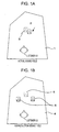
- Figs. 1A and 1B are illustrations showing the relationship between the position of a sound source and the position of a sound image perceived by a listener in a sound field space.
- Fig. 1A shows the relationship between the position of a sound source and the position of a perceptual sound image perceived by a listener in an actual sound field.
- Fig. 1B shows the relationship between the playback position and the position of a perceptual sound image perceived by a listener in a reproduction sound field.
- the perceptual sound image position perceived by the listener differs from the physical sound image position.
- an actual sound source 2 is arranged in an actual sound field space 1 shown in Fig. 1A, there are cases in which the position of a perceptual sound image 3 perceived by a listener U1 differs from the position of the actual sound source 2.
- a dummy head microphone for the purpose of picking up sound at positions of the two ears of the listener.
- the dummy head microphone is configured by mounting microphones at positions of the two ears of a dummy head produced by imitating, for example, the shape and the size of the head and the pinna of a human being.
- Fig. 2 is an illustration of an example of sound pickup using a dummy head microphone.
- the dummy head microphone 13 when sound pickup is performed using a dummy head microphone 13, originally, the dummy head microphone 13 is arranged at a position where the listener should listen in an actual sound field space 11, and direct sound that directly arrives from an actual sound source 12 and reflected sound that is reflected at a wall, a floor, a ceiling, etc., is picked up using microphones mounted on the corresponding two ear positions of a dummy head. Then, the sounds picked up by the individual microphones are output as a left sound pickup signal SL and a right sound pickup signal SR.
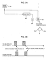
- the sense of hearing of a human being has properties such that, among sounds originating from the same sound source, the sound image is localized in the direction of the sound that arrives earlier at the ears of the listener. Such properties of a human being are described with reference to Figs. 3A and 3B.
- a sound apparatus shown in Fig. 3A is considered.
- a sound source signal from a sound source 21 is output as is as a reproduction sound from a speaker 23.
- a signal such that a sound source signal from the sound source 21 is delayed by a delay circuit 22 is output as a reproduction sound from a speaker 24.
- the reproduction sound arrives at a listener U who listens at a position shown in Fig. 3A at a timing shown in Fig. 3B. That is, first, the reproduction sound of the speaker 23 arrives at the listener U. Then, the reproduction sound of the speaker 24 arrives at a timing that is delayed by the delay time due to the delay circuit 22. In this case, the position of the sound image perception of the listener U, shown in Fig. 3A, becomes the position of the speaker 23, at which the reproduction sound arrives earlier.
- the inventors of the present invention have made further studies on the properties of the sense of hearing and have found the following fact.
- the sense of hearing of a human being separates sound originating from the same sound source into low frequency components and high frequency components, and causes information on the direction of the sound source to be contained in the low frequency components, and if the low frequency components are output earlier, the listener can clearly perceive the sound localization even if the information of the sound source direction contained in the high frequency components is not accurate.
- a low-pass filter 25 is provided between the sound source 21 and the speaker 23, and a high-pass filter 26 and a delay circuit 22 are provided between the sound source 21 and the speaker 24.
- the reproduction sound arrives at the listener U who listens at the position shown in Fig. 4A at the timing shown in Fig. 4B. That is, also, in this case, first, the reproduction sound (the low frequency components) of the speaker 23 arrives at the listener U. Then, the reproduction sound (the high frequency components) of the speaker 24 arrives at the listener U at a timing delayed by the delay time due to the delay circuit 22. Therefore, the listener U shown in Fig. 4A obtains the perception of the sound image by the reproduction sound of the speaker 23 that arrives earlier, that is, the low tone range reproduced from the speaker 23. Then, in this case, it is possible to enable the listener U to clearly perceive the sound image with respect to the sound of the sound source, which is the same as the low tone range reproduced from the speaker 23.
- reproduction sound that is reproduced from the left speaker arrives at not only the left ear of the listener, but also the right ear.
- the sound pickup signal picked up by the dummy head microphone 13 shown in Fig. 2 is reproduced by a stereo reproduction system using an intensity-based method
- the left ear sound corresponding to the left sound pickup signal SL picked up by the dummy head microphone 13 and the right ear sound corresponding to the right sound pickup signal SR not only arrive at the corresponding left and right ears of the listener, but also arrive at the ears on the opposite sides.
- a stereophonic sound reproduction signal generation filter capable of canceling propagation characteristics from a playback speaker to the ears of the listener in a listening room is used. Then, if such a stereophonic sound reproduction signal generation filter is used, the signal input to the left channel of the filter is reproduced at only the left ear of the listener, and the signal input to the right channel of the filter is reproduced at only the right ear of the listener.
- Fig. 5 shows the configuration of a stereophonic sound reproduction signal generation filter.
- a description is given by using as an example a case in which a speaker is arranged to the left and to the right in the front of the listener U.
- a head diffraction transfer function of a path that starts from a left speaker 37 and that reaches the left ear EL of the listener U in a reproduction sound field space 39 is denoted as HLS
- a head diffraction transfer function of a path that starts from a right speaker 38 and that reaches the right ear ER of the listener U is denoted as HRS
- HR0 a head diffraction transfer function of a path that starts from the left speaker 37 and that reaches the right ear ER of the listener U
- HR0 head diffraction transfer function of a path that starts from the right speaker 38 and that reaches the left ear EL of the listener U
- a left sound pickup signal SLin from a dummy head microphone (not shown in Fig. 5) is input as a left channel signal
- a right sound pickup signal SRin is input as a right channel signal.
- the left sound pickup signal SLin that is used as a left channel signal is input to an adder 31 and a crosstalk canceling section 32.
- the right sound pickup signal SRin that is used as a right channel signal is input to an adder 34 and a crosstalk canceling section 33.
- crosstalk canceling sections 32 and 33 filters for canceling crosstalk components to the right ear ER of the listener U from the left speaker 37 and crosstalk components to the left ear EL of the listener U from the right speaker 38 are used respectively.
- propagation characteristics CR of the crosstalk canceling section 32 are denoted as -HRO/HRS
- propagation characteristics CL of the crosstalk canceling section 33 are denoted as -HLO/HLS.
- Such a left sound pickup signal SLin that passes through the crosstalk canceling section 32 is input as a cancel signal to the adder 34.
- the right sound pickup signal SRin that passes through the crosstalk canceling section 33 is input as a cancel signal to the adder 31.
- the adder 31 adds together the left sound pickup signal SLin and the cancel signal, which are input from the crosstalk canceling section 33, and outputs the signals.
- the output of the adder 31 is supplied to a correction block section 35.
- the adder 34 adds together the right sound pickup signal SRin and the cancel signal, which are input from the crosstalk canceling section 32, and supplies the signals to a correction block section 36.
- the correction block section 35 is a block section for correcting the reproduction system, including the left speaker 37, with respect to the left channel.
- the correction block section 35 is formed by a correction section 35a for correcting changes of the characteristics, which occur due to the crosstalk canceling section 33, and a speaker correction section 35b for correcting speaker characteristics.
- the propagation characteristics of the correction section 35a are denoted as 1/(1 - CL ⁇ CR).
- the propagation characteristics of the correction section 35b are denoted as 1/HLS.
- the output of the correction block section 35 is output as a left sound pickup signal SLout from the stereophonic sound reproduction signal generation filter 30.
- the correction block section 36 is a block section for correcting the reproduction system, including the right speaker 38, with respect to the right channel.
- the correction block section 36 is formed by a correction section 36a for correcting changes of the characteristics, which occur due to the crosstalk canceling section 32, and a speaker correction section 36b for correcting speaker characteristics.
- the propagation characteristics of the correction section 36a are denoted as 1/(1 - CL ⁇ CR).
- the propagation characteristics of the correction section 36b are denoted as 1/HRS.
- the output of the correction block section 36 is output as a right sound pickup signal SRout from the stereophonic sound reproduction signal generation filter 30.
- the left sound pickup signal SLout output from the stereophonic sound reproduction signal generation filter 30 is input to the left speaker 37 in the reproduction sound field space 39, and the right sound pickup signal SRout is input to the right speaker 38 in the reproduction sound field space 39.
- the left ear EL of the listener U in the reproduction sound field space only the left ear sound corresponding to the left sound pickup signal SLin input to the stereophonic sound reproduction signal generation filter 30 can be reproduced.
- the right ear ER of the listener U similarly, only the right ear sound corresponding to the right sound pickup signal SRin input to the stereophonic sound reproduction signal generation filter 30 can be reproduced.
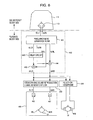
- Fig. 6 shows the configuration of a sound apparatus according to a first embodiment of the present invention.
- the sound apparatus shown in Fig. 6 is formed of a sound pickup block and a playback block, which are sound reproduction apparatuses.
- the sound pickup block is formed by the dummy head microphone 13 arranged in the actual sound field space 11.
- sound is picked up by the dummy head microphone 13, and a left sound pickup signal SL1 and a right sound pickup signal SR1, which are converted into electrical signals, are output to a microphone amplifying section 40 on the playback block side.
- the microphone amplifying section 40 includes a frequency band separation filter 41, a delay circuit 42, and adders 43 and 44.
- the frequency band separation filter 41 separates the left sound pickup signal SL1 and the right sound pickup signal SR1, which are input from the dummy head microphone 13, into corresponding signals of low frequency components (low frequency signals) SLL and SRL, and signals of high frequency components (high frequency signals) SLH and SRH with, for example, approximately 3 kHz being set as a boundary.
- the reason for setting the boundary frequency to 3 kHz in this embodiment is that the error between the standard dummy head microphone 13 and the head diffraction transfer function of the listener begins to increase from approximately 1 kHz, further increases when exceeding approximately 3 kHz, and the fundamental frequency components of speech, musical instrument sounds, etc., are contained within 3 kHz at the highest.
- the boundary frequency of the frequency band separation filter 41 needs not always to be set to 3 kHz, and may be set to any frequency between, for example, 1 kHz and 3 kHz.
- the left high frequency signal SLH and the right high frequency signal SRH which are separated by the frequency band separation filter 41, are input to the delay circuit 42.
- the left high frequency signal SLH and right high frequency signal SRH which are input, are delayed by a set delay time and are output.
- the left high frequency signal SLH and the right high frequency signal SRH in the delay circuit 42 are output by being delayed by several milliseconds to several tens of milliseconds from the output timing of the left low frequency signal SLL and the right low frequency signal SRL.
- a delay time needs only to be set I within a time in which the high tone range that is finally reproduced by being delayed is not heard as echo sound of a low tone range to the listener U.
- the adder 43 adds together the left high frequency signal SLH from the delay circuit 42 and the left low frequency signal SLL from the frequency band separation filter 41. Then, the added output of the adder 43 is output as a left sound pickup signal SL2.
- the adder 44 adds together the right high frequency signal SRH from the delay circuit 42 and the right low frequency signal SRL from the frequency band separation filter 41. Then, the added output of the adder 44 is output as a right sound pickup signal SR2.
- the left sound pickup signal SL2 and the right sound pickup signal SR2 output from the microphone amplifying section 40 are input to the stereophonic sound reproduction signal generation filter 30.
- the stereophonic sound reproduction signal generation filter 30 a filter capable of canceling propagation characteristics from speakers 46 and 47 to the ears of the listener U is used.
- the left sound pickup signal SL2 and the right sound pickup signal SR2 input from the microphone amplifying section 40 are input as a left sound pickup signal SL3 and a right sound pickup signal SR3 to the corresponding speakers 46 and 47.
- the left ear sound picked up at the position of the left ear of the dummy head microphone 13 arranged in the actual sound field space 11 can be reproduced at only the left ear EL of the listener U in a reproduction sound field space 45. Furthermore, the right ear sound picked up at the position of the right ear of the dummy head microphone 13 can be reproduced at only the right ear ER of the listener U.
- the playback block is formed of a headphone
- the left sound pickup signal SL2 and the right sound pickup signal SR2 output from the microphone amplifying section 40 are input to a headphone 49 via a filter 48 for a headphone.
- a filter 48 for a headphone a filter for making corrections in accordance with the characteristics of the headphone 49 is used.
- the microphone amplifying section 40 in the microphone amplifying section 40, only the high frequency components of the left sound pickup signal SL1 and the right sound pickup signal SR1 input from the dummy head microphone 13 are delayed by the delay circuit 42. That is, in this embodiment, only the high frequency components are delayed in which the influence of the head-related transfer function for which the individual differences are large tends to appear as sound image perception.
- the sound apparatus of this embodiment since the influence of the individual differences with respect to the sound image perception can be reduced, even when the stereophonic sound reproduction signal generation filter 30 is configured by using a standard head-related transfer function, it is possible to enable the listener U to perceive a target sensation of sound localization, for example, a sensation of sound localization as if the listener is in the actual sound field space 11.
- the delay circuit 42 may also be configured by using the phase delay characteristics of the frequency band separation filter 41.
- Fig. 7 shows the configuration of a sound apparatus according to a second embodiment of the present invention.
- Components of the sound apparatus in Fig. 7, which are identical to the components of the sound apparatus shown in Fig. 6, are designated with the same reference numerals, and accordingly, detailed descriptions thereof are omitted.
- the I sound apparatus shown in Fig. 7 differs from the sound apparatus shown in Fig. 6 in the configuratidn of a microphone amplifying section 50 provided in the sound pickup block.
- the left sound pickup signal SL1 and the right sound pickup signal SR1 input from the dummy head microphone 13 are input to the delay circuit 42 and a low-pass filter 51.
- the low-pass filter (LPF) 51 for example, only the low frequency components lower than or equal to 3 kHz are separated from the left sound pickup signal SL1 and right sound pickup signal SR1, which are input.
- the frequency band that can be separated by the low-pass filter 51 is set to be lower than or equal to 3 kHz, this is only an example.
- the frequency band can be set to any frequency between, for example, 1 kHz to 3 kHz.
- the left low frequency signal SLL output from the low-pass filter 51 is input to the adder 43.
- the right low frequency signal SRL output from the low-pass filter 51 is output to the adder 44.
- the left sound pickup signal SL1 delayed by the delay circuit 42 and the left low frequency signal SLL from the low-pass filter 51 are added together, and the added output is output as a left sound pickup signal SL2.
- the right sound pickup signal SR1 delayed by the delay circuit 42 and the right low frequency signal SRL from the low-pass filter 51 are added together, and the added output is output as a right sound pickup signal SR2.
- the microphone amplifying section 50 of the sound apparatus shown in Fig. 7 is such that, in place of the frequency band separation filter 41 provided in the microphone amplifying section 40 shown in Fig. 6, the low-pass filter 51 for separating only the low frequency components is provided.
- the reproduction sound of the low frequency components is output earlier from the speakers 46 and 47. Therefore, in any case of the two-channel speaker playback and the headphone playback, it is possible to enable the listener U to perceive the sensation of sound localization by the reproduction sound of the low frequency components that arrive earlier.
- a sound pickup signal is obtained by binaural sound pickup from the actual sound field space 11 by using the dummy head microphone 13.
- this is only an example, and even when microphones are installed at both ears of a human being in place of a dummy head, a sound pickup signal can also be obtained by binaural sound pickup in a similar manner.
- binaural sound pickup by picking up the left sound pickup signal SL1 and the right sound pickup signal SR1 input to the sound pickup block by mounting a dummy head microphone or by mounting microphones at both ears of a human being, binaural sound pickup is performed.
- This is only an example, and, for example, it is also possible to use a sound source signal that is not picked up by binaural sound pickup.
- Fig. 8 shows the configuration of a sound apparatus according to a third embodiment of the present invention.
- Components of the sound apparatus shown in Fig. 8, which are identical to the components of the sound apparatus shown in Fig. 6, are designated with the same reference numerals, and I accordingly, detailed descriptions thereof are omitted.
- the sound apparatus shown in Fig. 8 differs from the sound apparatus shown in Fig. 6 in that a binaural sound pickup signal generation circuit 60 is provided.
- the binaural sound pickup signal generation circuit 60 for example, by superposing, on the sound source signal, the propagation characteristics for each propagation path of sound waves and the head-related transfer function for each incidence angle to the listening position in an indoor space, a signal such that the total sum for the propagation paths is a hearing sound is obtained.
- signals corresponding to the binaural sound pickup signals that is, signals corresponding to the left sound pickup signal SL1 and the right sound pickup signal SR1 are obtained from the sound source signal.
- the sound source signal input to the binaural sound pickup signal generation circuit 60 may be any of an audio signal of an existing source, an audio signal synthesized by an electronic musical instrument, etc.
- any audio method for example, a monaural method, a stereo method, and a surround method, may be used.
- the left sound pickup signal SL1 and the right sound pickup signal SR1 in the binaural sound pickup signal generation circuit 60 first, based on the acoustic characteristics of a concert hall, etc., and the radiation directional characteristics of the sound source, how the sound radiated from the sound source propagates in the indoor space is computed. More specifically, first, based on wall surface acoustic characteristics such as the sound reflection/absorption characteristics of the shape of the acoustic space such as a concert hall, a wall surface, a floor, and a ceiling, the radiation directional characteristics of the sound source position and the sound source, and the directional characteristics of the listening point position and the hearing microphone, the propagation characteristics of sound waves from the sound source to the listening position are computed.
- Fig. 9A is a schematic view showing an actual propagation path from the position of the sound source to both ears of the listener in an indoor space.
- the actual sound field space 11 such as a concert hall
- sound waves are reflected on the wall surface, the floor, the ceiling, etc., and arrive toward the listening position (in this case, the dummy head microphone 13 indicated by the broken line is arranged at the listening position) from various directions.
- the direction of the sound source and the distance to the sound source when viewed from the listening position are computed, and the sound source signal is superposed on the head diffraction transfer function data in the direction of the sound source and at the distance to the sound source.
- the head diffraction transfer function data in the direction of the sound source and at the distance to the sound source may be obtained as follows. That is, the head diffraction transfer function data is measured in advance for each direction of the sound source and for each distance to the sound source. The head diffraction transfer function data of the closest angle is extracted from the head diffraction transfer function data from among the head diffraction transfer function data stored in the memory, and based on the data, the head diffraction transfer function data of a desired angle (the direction of the sound source) is obtained by an interpolation process.
- the above-described head diffraction transfer function data differs depending not only on the direction of the sound source but also on the distance from the sound source.
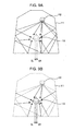
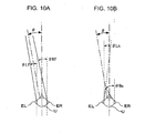
- the reason for this is that, as shown in Figs. 10A and 10B, when the distances from the left and right ears of the listener to the position of the sound source differs from each other, the incidence angle differs even if the direction ⁇ of the sound source is the same.
- the incidence angle ⁇ Lf of sound waves that arrive at the left ear EL of the listener U and the incidence angle ⁇ Rf of sound waves that arrive at the right ear ER of the listener U are shown in Fig. 10A.
- the incidence angle ⁇ Ln of sound waves that arrive at the left ear EL of the listener U and the incidence angle ⁇ Rn of sound waves that arrive at the right ear ER of the listener U are shown in Fig. 10B.
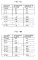
- Figs. 11A and 11B correspondence tables in which the direction of the sound source with respect to both ears of the listener corresponds to the head diffraction transfer function data are provided according to the distance from the sound source to far.
- Fig. 11A shows an example of a correspondence table when the distance from the position of the sound source to the listening position is a long distance.
- Fig. 11B shows an example of a correspondence table when the distance from the position of the sound source to the listening position is near.
- correspondence table if there is no limitation on the storage capacity of the memory in which the data is stored, it is also possible to subdivide the distance to the sound source, so that the correspondence table of head diffraction transfer function data, in which the subdivided distances and the direction of the sound source are parameters, is stored in the memory.
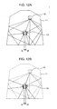
- Fig. 12A is a schematic view showing an actual propagation path from the position of the sound source to the center position of the listener at the listening position in an indoor space.
- sound waves arrive at the dummy head microphone 13 at the listening position from various directions.
- the direction of the sound source and the distance to the sound source when viewed from the listening position are computed, and the sound source signal is superposed on the head diffraction transfer function data in the direction of the sound source and at the distance to the sound source.
- the head diffraction transfer function data in the direction of the sound source and at the distance to the sound source may be obtained as follows. That is, the head diffraction transfer function data is measured in advance for each direction of the sound source and for each distance to the sound source. The head diffraction transfer function data of the closest angle is extracted from the head diffraction transfer function data from among the head diffraction transfer function data stored in the memory, and based on the data, the head diffraction transfer function data of a desired angle (the direction of the sound source) is obtained by an interpolation process.
- the head diffraction transfer function data in this case differs according to not only the direction of the sound source but also the distance from the sound source. The reason for this is that, as shown in Fig. 13, when the distance from the center position of the listener to the sound source differs, the incidence angle differs even if the sound source direction ⁇ is the same.
- a correspondence table in which the direction of the sound source with respect to the center position of the listener corresponds to the head diffraction transfer function data is provided according to the distance from the sound source to the listening position.
- correspondence table if there is no limitation on the storage capacity of the memory for storage, of course, it is also possible to subdivide the distance to the sound source, so that the correspondence table of head diffraction transfer function data, in which the distance to the sound source and the direction of the sound source are parameters, is stored in the memory.
- the sound pickup block of the sound apparatus according to this embodiment may be configured in another way.
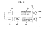
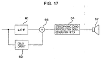
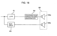
- Figs. 15 to 18 show other examples of the configuration of the sound pickup block of the sound apparatus according to this embodiment. In Figs. 15 to 18, only the configuration of the speaker reproduction system for one channel from among the two-channel speaker playback blocks is shown.
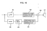
- the playback block shown in Fig. 15 includes a low-pass filter (LPF) 61, a high-pass filter (HPF) 62, a delay circuit 63, stereophonic sound reproduction signal generation filters 64 and 65, an adder 66, and a speaker 67.
- LPF low-pass filter
- HPF high-pass filter
- the stereophonic sound reproduction signal generation filter 64 performs a filtering process for generating a stereophonic sound reproduction signal with respect to low frequency components that pass through the low-pass filter (LPF) 61 from among the input signals from the sound pickup block at the previous stage (not shown).
- LPF low-pass filter
- the stereophonic sound reproduction signal generation filter 65 performs a filtering process for generating a stereophonic sound reproduction signal. Then, the adder 66 adds together the output of the stereophonic sound reproduction signal generation filter 64 and the output of the stereophonic sound reproduction signal generation filter 65, and outputs the combined output.
- the playback block shown in Fig. 16 does not add the output of the stereophonic sound reproduction signal generation filter 64 and the output of the stereophonic sound reproduction signal generation filter 65, and the reproduction signal of the low frequency components output from the stereophonic sound reproduction signal generation filter 64 is reproduced using a woofer 68a of a speaker system 68, the woofer 68a playing back the low frequencies. Then, the reproduction signal of the high frequency components output from the stereophonic sound reproduction signal generation filter 65 is reproduced using a tweeter 68b of the speaker system 68, the tweeter 68b playing back medium to high frequency components.
- the adder 66 adds together the low frequency component signal that pass through the low-pass filter (LPF) 61 from among the input signals and the signal such that the input signal is delayed by a predetermined time by the delay circuit 63. Then, the added output of the adder 66 is supplied to the speaker 67 through the stereophonic sound reproduction signal generation filter 64.
- LPF low-pass filter
- the low frequency component signal output from the LPF 61 is reproduced by the woofer 68a of the speaker system 68 through the stereophonic sound reproduction signal generation filter 64, and the output of the delay circuit 63 is reproduced by the tweeter 68b of the speaker system 68.
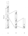
- Fig. 21 is a schematic view showing an example of data structure of a recording medium in that case.
- packs composed of, for example, a video packet, a subtitle packet, a plurality of audio packet 1, audio packet 2,... audio packet n are formed.
- a pack header is attached to the beginning thereof. In the pack header, for example, additional information serving as a reference during synchronous playback is given.
- the audio packet is composed of a plurality of audio channel 1, audio channel 2,... audio channel n, and a packet header is attached to the beginning thereof.
- a packet header for example, various kinds of control data used for audio control are recorded. For example, a sampling frequency, the number of multiplexing channels, a crossover frequency, a data coding method code indicating a data coding method, an audio signal specification code indicating the specification (format) of an audio signal playback method, etc., are recorded.
- a channel header is attached to the beginning of the data.
- pieces of data indicating a channel number, a frequency band, a gain, and the amount of phase are recorded as additional information.
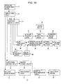
- Fig. 19 is a block diagram showing the configuration of the above-described AV system. It is assumed in this case that video data and subtitle data are multiplexed with audio data on the recording medium. Furthermore, it is assumed in this case that, as audio data to be recorded on recording medium, audio data is recorded such that a signal picked up by the above-described dummy head microphone is separated into low frequency components and high frequency components, the high frequency components are delayed, and these components are multiplexed.
- an optical disc playback section 71 reads multiplexed data recorded on an optical disc.
- a demultiplexing circuit 72 detects and separates the header, the video data, the subtitle data, and the audio data of a plurality of channels from the read multiplexed data.
- An audio data decoding circuit 73 decodes the audio data transmitted from the demultiplexing circuit 72. At this time, the audio data decoding circuit 73 outputs the ultra-low frequency data among the decoded audio data to an ultra-low frequency buffer circuit 81 and outputs the low frequency data to a low frequency buffer circuit 84. Furthermore, the audio data decoding circuit 73 outputs the high frequency data to a high frequency buffer circuit 88.
- the ultra-low frequency buffer circuit 81 converts the input ultra-low frequency data into an analog ultra-low frequency signal, and outputs the signal.
- the low frequency buffer circuit 84 converts the input low frequency data into an analog low frequency signal, and outputs the signal.
- the high-frequency buffer circuit 88 converts the input high I frequency data into an analog high frequency signal, and outputs the signal.
- a power amplifying circuit 82 amplifies the ultra-low frequency signal from the ultra-low frequency buffer circuit 81 to a predetermined level, and thereafter outputs the signal to a subwoofer speaker system 83, whereby the signal is output.
- a delay circuit 89 delays the high frequency signal from the high-frequency buffer circuit 88 by a predetermined time and outputs the signal.
- a stereophonic sound reproduction signal generation filter 85 combines the low frequency signal input from the low frequency buffer circuit 84 and the high frequency signal delayed by a predetermined time by the delay circuit 89, thereafter performs a stereophonic sound reproduction signal generation process on the signals, and outputs them to a power amplifying circuit 86.
- the power amplifying circuit 86 after the audio signal from the stereophonic sound reproduction signal generation filter 85 is amplified to a predetermined level, the signal is output to a speaker system 87, whereby the signal is output.
- a subtitle data decoding circuit 74 decodes subtitle data from a subtitle packet in accordance with timing information contained in the header information transmitted from the demultiplexing circuit 72, and outputs the subtitle data.
- a video data decoding circuit 75 decodes the video data in accordance with the frame rate contained in the header information transmitted from the demultiplexing circuit 72, and outputs the data.
- a subtitle playback circuit 76 performs a predetermined playback process on the subtitle data decoded by the subtitle data decoding circuit 74, and outputs the data as a subtitle signal.
- a video playback circuit 77 performs a predetermined playback process on the video data decoded by the video data decoding circuit 75, and outputs the data as a video signal.
- a subtitle/superimposition circuit 78 performs a so-called superimposition process of superimposing a subtitle signal onto a video signal in accordance with timing information, such as subtitle control information, recorded as the header information in the packet header attached to the subtitle packet, converts the signal into a video signal format in compliance with a video display section 79, and outputs the signal.
- a video display section 79 displays a video image on the basis of the video signal supplied from the subtitle/superimposition circuit 78.
- a control section 80 controls the entire AV system 70 and performs various kinds of control by using the header information demultiplexed from the multiplexed data in the demultiplexing circuit 72. For example, switching control for switching the operation of the audio data decoding circuit 73 is performed in accordance with the sampling frequency and the data coding method code attached to the packet header shown in Fig. 20.
- the audio packet matching the specification of the audio reproduction system is selected from the audio signal specification (format) code attached to the packet header in a similar manner. For example, if the audio packet 1 is an audio packet of a binaural system, the audio packet being picked up by the sound apparatus according to this embodiment, and the audio packet 2 is an audio packet of a surround playback system, the audio packet 1 is selected.
- FIG. 20 The block configuration of the AV system in that case is shown in Fig. 20.
- Blocks in Fig. 20, which are identical to the blocks shown in Fig. 19, are designated with the same reference numerals, and accordingly, detailed descriptions thereof are omitted.
- An AV system 90 shown in Fig. 20 differs from the AV system 70 shown in Fig. 19 in that, as shown in Fig. 20, a frequency band separation circuit 91 is provided between the audio data decoding circuit 73 and the buffer circuits 81, 84, and 88.
- the audio data that is read from the optical disc and that is decoded by the audio data decoding circuit 73 is separated into ultra-low frequency data, high frequency data, and low frequency data.
- the ultra-low frequency data that is separated by the frequency band separation circuit 91 in this manner is supplied to the ultra-low frequency buffer circuit 81, the low frequency data is supplied to the low frequency buffer circuit 84, and the high frequency data is supplied to the high-frequency buffer circuit 88.
- the embodiment has been discussed above by assuming that, in such an AV system, various kinds of data to be played back, in which video data, subtitle data, and audio data of a plurality of audio channels are multiplexed, is recorded on a recording medium, such as an optical disc.
- a recording medium such as an optical disc.
- the AV system can also be configured in such a way that data to be played back, such as video data, subtitle data, and audio data of a plurality of audio channels, is received, for example, via a network.
- a subwoofer playback system for playing back ultra-low frequency components is provided.
- a subwoofer playback system needs not to be provided.
Landscapes
- Engineering & Computer Science (AREA)
- Life Sciences & Earth Sciences (AREA)
- Physics & Mathematics (AREA)
- Ecology (AREA)
- Forests & Forestry (AREA)
- Mechanical Engineering (AREA)
- Biodiversity & Conservation Biology (AREA)
- Acoustics & Sound (AREA)
- Signal Processing (AREA)
- Wood Science & Technology (AREA)
- Botany (AREA)
- Environmental Sciences (AREA)
- Stereophonic System (AREA)
- Stereophonic Arrangements (AREA)
Applications Claiming Priority (2)
| Application Number | Priority Date | Filing Date | Title |
|---|---|---|---|
| JP2004030876A JP2005223713A (ja) | 2004-02-06 | 2004-02-06 | 音響再生装置、音響再生方法 |
| JP2004030876 | 2004-02-06 |
Publications (2)
| Publication Number | Publication Date |
|---|---|
| EP1562401A2 true EP1562401A2 (de) | 2005-08-10 |
| EP1562401A3 EP1562401A3 (de) | 2007-11-14 |
Family
ID=34675563
Family Applications (1)
| Application Number | Title | Priority Date | Filing Date |
|---|---|---|---|
| EP05250362A Withdrawn EP1562401A3 (de) | 2004-02-06 | 2005-01-25 | Tonwiedergabegerät und Verfahren zur Tonwiedergabe |
Country Status (5)
| Country | Link |
|---|---|
| US (1) | US8027476B2 (de) |
| EP (1) | EP1562401A3 (de) |
| JP (1) | JP2005223713A (de) |
| KR (1) | KR20060041736A (de) |
| CN (1) | CN1658709B (de) |
Cited By (3)
| Publication number | Priority date | Publication date | Assignee | Title |
|---|---|---|---|---|
| EP2630808A4 (de) * | 2010-10-20 | 2016-01-20 | Dts Llc | System zur verbreiterung von stereobildern |
| EP3726858A1 (de) * | 2019-04-16 | 2020-10-21 | Fraunhofer Gesellschaft zur Förderung der Angewand | Reproduktion einer unteren schicht |
| RU2804680C2 (ru) * | 2019-04-16 | 2023-10-03 | Фраунхофер-Гезелльшафт Цур Фердерунг Дер Ангевандтен Форшунг Е.Ф. | Воспроизведение на нижнем уровне |
Families Citing this family (26)
| Publication number | Priority date | Publication date | Assignee | Title |
|---|---|---|---|---|
| US20090041254A1 (en) * | 2005-10-20 | 2009-02-12 | Personal Audio Pty Ltd | Spatial audio simulation |
| US8000958B2 (en) * | 2006-05-15 | 2011-08-16 | Kent State University | Device and method for improving communication through dichotic input of a speech signal |
| CN101960866B (zh) * | 2007-03-01 | 2013-09-25 | 杰里·马哈布比 | 音频空间化及环境模拟 |
| JP4518151B2 (ja) | 2008-01-15 | 2010-08-04 | ソニー株式会社 | 信号処理装置、信号処理方法、プログラム |
| US10158958B2 (en) | 2010-03-23 | 2018-12-18 | Dolby Laboratories Licensing Corporation | Techniques for localized perceptual audio |
| CN108989721B (zh) * | 2010-03-23 | 2021-04-16 | 杜比实验室特许公司 | 用于局域化感知音频的技术 |
| EP2719200B1 (de) * | 2011-06-09 | 2019-12-25 | Sony Ericsson Mobile Communications AB | Reduzierung des datenvolumens kopfbezogenener übertragungsfunktionen |
| KR101676634B1 (ko) * | 2012-08-31 | 2016-11-16 | 돌비 레버러토리즈 라이쎈싱 코오포레이션 | 오브젝트―기반 오디오를 위한 반사된 사운드 렌더링 |
| FI20135125L (fi) * | 2013-02-12 | 2014-08-13 | Hannu Hätinen | Laitteisto ja menetelmä auditiivisen viiveen korjaamiseksi |
| JP6539943B2 (ja) * | 2014-02-07 | 2019-07-10 | 日産自動車株式会社 | 車両の付加音量算出方法および付加音量算出装置 |
| WO2015134658A1 (en) | 2014-03-06 | 2015-09-11 | Dolby Laboratories Licensing Corporation | Structural modeling of the head related impulse response |
| DE102014210215A1 (de) * | 2014-05-28 | 2015-12-03 | Fraunhofer-Gesellschaft zur Förderung der angewandten Forschung e.V. | Ermittlung und Nutzung hörraumoptimierter Übertragungsfunktionen |
| WO2018006856A1 (zh) * | 2016-07-07 | 2018-01-11 | 腾讯科技(深圳)有限公司 | 一种回声消除的方法及终端、计算机存储介质 |
| CN106162206A (zh) * | 2016-08-03 | 2016-11-23 | 北京疯景科技有限公司 | 全景录制、播放方法及装置 |
| JP6753329B2 (ja) * | 2017-02-15 | 2020-09-09 | 株式会社Jvcケンウッド | フィルタ生成装置、及びフィルタ生成方法 |
| JP6791001B2 (ja) * | 2017-05-10 | 2020-11-25 | 株式会社Jvcケンウッド | 頭外定位フィルタ決定システム、頭外定位フィルタ決定装置、頭外定位決定方法、及びプログラム |
| US11122384B2 (en) * | 2017-09-12 | 2021-09-14 | The Regents Of The University Of California | Devices and methods for binaural spatial processing and projection of audio signals |
| JP7413267B2 (ja) * | 2018-10-16 | 2024-01-15 | ドルビー ラボラトリーズ ライセンシング コーポレイション | 低音マネジメントのための方法及び装置 |
| JP7533223B2 (ja) * | 2019-01-24 | 2024-08-14 | ソニーグループ株式会社 | オーディオシステム、オーディオ再生装置、サーバー装置、オーディオ再生方法及びオーディオ再生プログラム |
| CN113994716B (zh) * | 2019-06-21 | 2025-01-21 | 索尼集团公司 | 信号处理装置和方法以及程序 |
| WO2021061675A1 (en) * | 2019-09-23 | 2021-04-01 | Dolby Laboratories Licensing Corporation | Audio encoding/decoding with transform parameters |
| CN113875265A (zh) * | 2020-04-20 | 2021-12-31 | 深圳市大疆创新科技有限公司 | 音频信号处理方法、音频处理装置及录音设备 |
| CN113596647B (zh) * | 2020-04-30 | 2024-05-28 | 深圳市韶音科技有限公司 | 声音输出装置及调节声像的方法 |
| EP4124067B1 (de) | 2020-04-30 | 2025-12-10 | Shenzhen Shokz Co., Ltd. | Tonausgabevorrichtung |
| IT202100010502A1 (it) * | 2021-04-26 | 2022-10-26 | Iinformatica S R L | Metodo e relativo dispositivo innovativo per il green sensing ossia per il controllo e l’ascolto dello stato di piante e alberi |
| JP7716132B1 (ja) | 2024-03-01 | 2025-07-31 | Whismr合同会社 | 収音装置 |
Family Cites Families (36)
| Publication number | Priority date | Publication date | Assignee | Title |
|---|---|---|---|---|
| JPS5739113A (en) | 1980-08-20 | 1982-03-04 | Nippon Kokan Kk <Nkk> | Steel-making process by converter |
| FR2567142B1 (fr) | 1984-07-04 | 1986-09-12 | Raffinage Cie Francaise | Procede perfectionne de craquage catalytique |
| JPS625713A (ja) | 1985-07-01 | 1987-01-12 | Clarion Co Ltd | 狭帯域伝送系の音質補償回路 |
| US4893342A (en) * | 1987-10-15 | 1990-01-09 | Cooper Duane H | Head diffraction compensated stereo system |
| EP0407037B1 (de) | 1989-06-12 | 1994-09-21 | Merck & Co. Inc. | Verfahren zur Entfernung von bakteriellen Endotoxinen aus gram-negativen Polysacchariden |
| US5185801A (en) * | 1989-12-28 | 1993-02-09 | Meyer Sound Laboratories Incorporated | Correction circuit and method for improving the transient behavior of a two-way loudspeaker system |
| JPH04284100A (ja) | 1991-03-12 | 1992-10-08 | Clarion Co Ltd | 車室内音場再生装置 |
| JPH04364700A (ja) | 1991-06-12 | 1992-12-17 | Matsushita Electric Ind Co Ltd | 音場補正装置 |
| JPH0530600A (ja) | 1991-07-23 | 1993-02-05 | Fujitsu Ten Ltd | 音像制御装置 |
| JP2932801B2 (ja) | 1991-10-22 | 1999-08-09 | 株式会社大林組 | 立体音場シミュレーション方法 |
| EP0553832B1 (de) * | 1992-01-30 | 1998-07-08 | Matsushita Electric Industrial Co., Ltd. | Schallfeldsteuerungssystem |
| JPH06165298A (ja) | 1992-11-24 | 1994-06-10 | Nissan Motor Co Ltd | 音響再生装置 |
| JP3374425B2 (ja) | 1993-01-19 | 2003-02-04 | ソニー株式会社 | 音響装置 |
| US5666425A (en) | 1993-03-18 | 1997-09-09 | Central Research Laboratories Limited | Plural-channel sound processing |
| US5536773A (en) | 1993-07-16 | 1996-07-16 | Mitsui Petrochemical Industries, Ltd. | Polypropylene resin composition and the use of the same |
| JPH07107598A (ja) | 1993-09-29 | 1995-04-21 | Toshiba Corp | 音像拡大装置 |
| GB9326092D0 (en) * | 1993-12-21 | 1994-02-23 | Central Research Lab Ltd | Apparatus and method for audio signal balance control |
| US5841879A (en) * | 1996-11-21 | 1998-11-24 | Sonics Associates, Inc. | Virtually positioned head mounted surround sound system |
| IT1268925B1 (it) * | 1994-04-12 | 1997-03-13 | Syfal Srl | Apparecchiatura per l'incisione di matrici cilindriche in gomma. |
| WO1995034883A1 (en) | 1994-06-15 | 1995-12-21 | Sony Corporation | Signal processor and sound reproducing device |
| JP3385725B2 (ja) * | 1994-06-21 | 2003-03-10 | ソニー株式会社 | 映像を伴うオーディオ再生装置 |
| JPH08182100A (ja) | 1994-10-28 | 1996-07-12 | Matsushita Electric Ind Co Ltd | 音像定位方法および音像定位装置 |
| JPH09163346A (ja) | 1995-12-11 | 1997-06-20 | Toshiba Corp | テレビ応答サーバシステム |
| WO1997025834A2 (en) | 1996-01-04 | 1997-07-17 | Virtual Listening Systems, Inc. | Method and device for processing a multi-channel signal for use with a headphone |
| JPH09327099A (ja) | 1996-06-06 | 1997-12-16 | Sony Corp | 音響再生装置 |
| JPH1070798A (ja) | 1996-06-21 | 1998-03-10 | Yamaha Corp | 3次元音響再生装置 |
| JP3131564B2 (ja) | 1996-07-03 | 2001-02-05 | 松下電器産業株式会社 | 放送システム、サービス提供装置及び受信端末装置 |
| JPH10164447A (ja) | 1996-11-25 | 1998-06-19 | Matsushita Electric Ind Co Ltd | 放送受信装置 |
| JPH10320413A (ja) | 1997-05-22 | 1998-12-04 | Matsushita Electric Ind Co Ltd | ユーザプロファイル情報管理システム |
| JPH1188280A (ja) | 1997-09-12 | 1999-03-30 | Sharp Corp | 放送サービスの案内システム |
| GB9726338D0 (en) * | 1997-12-13 | 1998-02-11 | Central Research Lab Ltd | A method of processing an audio signal |
| JP2000333297A (ja) | 1999-05-14 | 2000-11-30 | Sound Vision:Kk | 立体音生成装置、立体音生成方法及び立体音を記録した媒体 |
| JP3586401B2 (ja) | 1999-12-09 | 2004-11-10 | 本田技研工業株式会社 | 自動変速機の制御装置 |
| JP2001346298A (ja) | 2000-06-06 | 2001-12-14 | Fuji Xerox Co Ltd | バイノーラル再生装置及び音源評価支援方法 |
| AUPQ941600A0 (en) * | 2000-08-14 | 2000-09-07 | Lake Technology Limited | Audio frequency response processing sytem |
| CN100481722C (zh) | 2002-06-05 | 2009-04-22 | 索尼克焦点公司 | 声虚拟现实引擎中增强传送音的系统和方法 |
-
2004
- 2004-02-06 JP JP2004030876A patent/JP2005223713A/ja active Pending
-
2005
- 2005-01-25 EP EP05250362A patent/EP1562401A3/de not_active Withdrawn
- 2005-02-03 US US11/049,911 patent/US8027476B2/en not_active Expired - Fee Related
- 2005-02-04 KR KR1020050010521A patent/KR20060041736A/ko not_active Ceased
- 2005-02-06 CN CN2005100655112A patent/CN1658709B/zh not_active Expired - Fee Related
Cited By (5)
| Publication number | Priority date | Publication date | Assignee | Title |
|---|---|---|---|---|
| EP2630808A4 (de) * | 2010-10-20 | 2016-01-20 | Dts Llc | System zur verbreiterung von stereobildern |
| EP3726858A1 (de) * | 2019-04-16 | 2020-10-21 | Fraunhofer Gesellschaft zur Förderung der Angewand | Reproduktion einer unteren schicht |
| WO2020212414A1 (en) * | 2019-04-16 | 2020-10-22 | Fraunhofer-Gesellschaft zur Förderung der angewandten Forschung e.V. | Lower layer reproduction |
| RU2804680C2 (ru) * | 2019-04-16 | 2023-10-03 | Фраунхофер-Гезелльшафт Цур Фердерунг Дер Ангевандтен Форшунг Е.Ф. | Воспроизведение на нижнем уровне |
| US12262191B2 (en) | 2019-04-16 | 2025-03-25 | Fraunhofer-Gesellschaft zur Förderung der angewandten Forschung e. V. | Lower layer reproduction |
Also Published As
| Publication number | Publication date |
|---|---|
| EP1562401A3 (de) | 2007-11-14 |
| CN1658709B (zh) | 2011-06-08 |
| JP2005223713A (ja) | 2005-08-18 |
| KR20060041736A (ko) | 2006-05-12 |
| CN1658709A (zh) | 2005-08-24 |
| US20050190925A1 (en) | 2005-09-01 |
| US8027476B2 (en) | 2011-09-27 |
Similar Documents
| Publication | Publication Date | Title |
|---|---|---|
| US8027476B2 (en) | Sound reproduction apparatus and sound reproduction method | |
| US8477951B2 (en) | Front surround system and method of reproducing sound using psychoacoustic models | |
| CN1235443C (zh) | 多声道音频重放装置和方法 | |
| US6577736B1 (en) | Method of synthesizing a three dimensional sound-field | |
| KR101368859B1 (ko) | 개인 청각 특성을 고려한 2채널 입체 음향 재생 방법 및장치 | |
| CN100586227C (zh) | 立体声扩展网络中的输出均衡 | |
| US7277551B2 (en) | Sound reproducing apparatus and sound reproducing method | |
| JP3435141B2 (ja) | 音像定位装置、並びに音像定位装置を用いた会議装置、携帯電話機、音声再生装置、音声記録装置、情報端末装置、ゲーム機、通信および放送システム | |
| CN1875656A (zh) | 来自于前置扬声器的多声道音频环绕声 | |
| JP2002159100A (ja) | 2チャネル・ステレオ・フォーマットの左及び右のチャネル入力信号を左及び右のチャネル出力信号に変換する方法及び信号処理装置 | |
| EP1562402A2 (de) | Tonaufnahmegerät, Verfahren zur Tonaufnahme und Aufzeichnungsmedium | |
| EP2229012B1 (de) | Vorrichtung, Verfahren, Programm und System zur Unterdrückung von Übersprechun bei der Tonwiedergabe über mehrere um den Hörer angeordnete Lautsprecher | |
| WO2002015637A1 (en) | Method and system for recording and reproduction of binaural sound | |
| CN1956606B (zh) | 产生空间立体声的方法和装置 | |
| CN102598718A (zh) | 用于再现具有改进的声像的多通道声音的扩音器系统 | |
| JP2002291100A (ja) | オーディオ信号再生方法、及びパッケージメディア | |
| KR101417065B1 (ko) | 가상 입체 음향 구현 장치 및 방법 | |
| JP2005328315A (ja) | 音響装置および記録方法 | |
| KR101526014B1 (ko) | 다채널 서라운드 스피커 시스템 | |
| JP2003032782A (ja) | 音響再生装置 | |
| Sibbald | Transaural acoustic crosstalk cancellation | |
| JP3942914B2 (ja) | ステレオ信号処理装置 | |
| JP2005184140A (ja) | 立体音響記録方法ならびに立体音響再生方法、立体音響再生装置 | |
| AU751831C (en) | Method and system for recording and reproduction of binaural sound | |
| JP2008011099A (ja) | ヘッドフォン音響再生システム、ヘッドフォン装置 |
Legal Events
| Date | Code | Title | Description |
|---|---|---|---|
| PUAI | Public reference made under article 153(3) epc to a published international application that has entered the european phase |
Free format text: ORIGINAL CODE: 0009012 |
|
| AK | Designated contracting states |
Kind code of ref document: A2 Designated state(s): AT BE BG CH CY CZ DE DK EE ES FI FR GB GR HU IE IS IT LI LT LU MC NL PL PT RO SE SI SK TR |
|
| AX | Request for extension of the european patent |
Extension state: AL BA HR LV MK YU |
|
| PUAL | Search report despatched |
Free format text: ORIGINAL CODE: 0009013 |
|
| AK | Designated contracting states |
Kind code of ref document: A3 Designated state(s): AT BE BG CH CY CZ DE DK EE ES FI FR GB GR HU IE IS IT LI LT LU MC NL PL PT RO SE SI SK TR |
|
| AX | Request for extension of the european patent |
Extension state: AL BA HR LV MK YU |
|
| 17P | Request for examination filed |
Effective date: 20080424 |
|
| AKX | Designation fees paid |
Designated state(s): DE FR GB |
|
| 17Q | First examination report despatched |
Effective date: 20110503 |
|
| STAA | Information on the status of an ep patent application or granted ep patent |
Free format text: STATUS: THE APPLICATION IS DEEMED TO BE WITHDRAWN |
|
| 18D | Application deemed to be withdrawn |
Effective date: 20110914 |