EP1562865B1 - System zur zufuhr von flüssigkeit - Google Patents
System zur zufuhr von flüssigkeit Download PDFInfo
- Publication number
- EP1562865B1 EP1562865B1 EP03774426A EP03774426A EP1562865B1 EP 1562865 B1 EP1562865 B1 EP 1562865B1 EP 03774426 A EP03774426 A EP 03774426A EP 03774426 A EP03774426 A EP 03774426A EP 1562865 B1 EP1562865 B1 EP 1562865B1
- Authority
- EP
- European Patent Office
- Prior art keywords
- flow regulator
- liquid
- light source
- pump
- supply
- Prior art date
- Legal status (The legal status is an assumption and is not a legal conclusion. Google has not performed a legal analysis and makes no representation as to the accuracy of the status listed.)
- Expired - Lifetime
Links
- 239000007788 liquid Substances 0.000 title claims abstract description 58
- 238000010079 rubber tapping Methods 0.000 claims description 27
- 230000004913 activation Effects 0.000 abstract 2
- 239000012530 fluid Substances 0.000 abstract 1
- XLYOFNOQVPJJNP-UHFFFAOYSA-N water Substances O XLYOFNOQVPJJNP-UHFFFAOYSA-N 0.000 description 50
- VYPSYNLAJGMNEJ-UHFFFAOYSA-N Silicium dioxide Chemical compound O=[Si]=O VYPSYNLAJGMNEJ-UHFFFAOYSA-N 0.000 description 11
- 244000005700 microbiome Species 0.000 description 7
- 238000004891 communication Methods 0.000 description 5
- 238000000746 purification Methods 0.000 description 5
- OKTJSMMVPCPJKN-UHFFFAOYSA-N Carbon Chemical compound [C] OKTJSMMVPCPJKN-UHFFFAOYSA-N 0.000 description 3
- 229910052799 carbon Inorganic materials 0.000 description 3
- 230000007257 malfunction Effects 0.000 description 3
- 230000002159 abnormal effect Effects 0.000 description 2
- 230000006378 damage Effects 0.000 description 2
- 238000010586 diagram Methods 0.000 description 2
- 239000003651 drinking water Substances 0.000 description 2
- 235000020188 drinking water Nutrition 0.000 description 2
- 238000005516 engineering process Methods 0.000 description 2
- ZAMOUSCENKQFHK-UHFFFAOYSA-N Chlorine atom Chemical compound [Cl] ZAMOUSCENKQFHK-UHFFFAOYSA-N 0.000 description 1
- 230000003213 activating effect Effects 0.000 description 1
- 230000015556 catabolic process Effects 0.000 description 1
- 229910052801 chlorine Inorganic materials 0.000 description 1
- 239000000460 chlorine Substances 0.000 description 1
- 230000001419 dependent effect Effects 0.000 description 1
- 230000005611 electricity Effects 0.000 description 1
- 239000012535 impurity Substances 0.000 description 1
- 230000007774 longterm Effects 0.000 description 1
- 238000004519 manufacturing process Methods 0.000 description 1
- 238000000034 method Methods 0.000 description 1
- 230000005855 radiation Effects 0.000 description 1
- 239000007787 solid Substances 0.000 description 1
- 230000001960 triggered effect Effects 0.000 description 1
Images

Classifications
-
- C—CHEMISTRY; METALLURGY
- C02—TREATMENT OF WATER, WASTE WATER, SEWAGE, OR SLUDGE
- C02F—TREATMENT OF WATER, WASTE WATER, SEWAGE, OR SLUDGE
- C02F1/00—Treatment of water, waste water, or sewage
- C02F1/008—Control or steering systems not provided for elsewhere in subclass C02F
-
- C—CHEMISTRY; METALLURGY
- C02—TREATMENT OF WATER, WASTE WATER, SEWAGE, OR SLUDGE
- C02F—TREATMENT OF WATER, WASTE WATER, SEWAGE, OR SLUDGE
- C02F1/00—Treatment of water, waste water, or sewage
- C02F1/30—Treatment of water, waste water, or sewage by irradiation
- C02F1/32—Treatment of water, waste water, or sewage by irradiation with ultraviolet light
-
- C—CHEMISTRY; METALLURGY
- C02—TREATMENT OF WATER, WASTE WATER, SEWAGE, OR SLUDGE
- C02F—TREATMENT OF WATER, WASTE WATER, SEWAGE, OR SLUDGE
- C02F2209/00—Controlling or monitoring parameters in water treatment
- C02F2209/005—Processes using a programmable logic controller [PLC]
-
- C—CHEMISTRY; METALLURGY
- C02—TREATMENT OF WATER, WASTE WATER, SEWAGE, OR SLUDGE
- C02F—TREATMENT OF WATER, WASTE WATER, SEWAGE, OR SLUDGE
- C02F2209/00—Controlling or monitoring parameters in water treatment
- C02F2209/40—Liquid flow rate
Definitions
- the present invention relates to a system for supplying liquid, comprising a tapping point for drawing off liquid from the system, a liquid pipe which connects the tapping point with a flow regulator, which in an active mode passes liquid from a liquid source through the pipe to the tapping point and in an inactive mode prevents the flow of liquid through the liquid pipe, a liquid purifier, which is connected to the liquid pipe between the tapping point and the flow regulator and which comprises an electrical UV light source and means for automatically lighting up the UV light source when the flow regulator is activated for passing liquid through the liquid pipe and the tapping point.
- the system is particularly suitable for use with mobile applications, such as in campers and caravans.
- campers there is a need to carry and store water for domestic requirements.
- the water is normally stored in a storage tank, which contains the normal requirements for anything from a couple of days up to several weeks.
- a storage tank which contains the normal requirements for anything from a couple of days up to several weeks.
- Such long-term storage can give rise to the growth of micro-organisms which can be harmful to the user, particularly if the water is used as drinking water. Tests have shown that water which is stored for a week in the storage tank of a camper exceeds the guidelines of the Swedish National Food Administration relating to the presence of micro-organisms in drinking water by a factor of 28.
- the water supply system can be equipped with a water purifier, which is connected in series between the storage tank and the tapping points.
- the water supply system can comprise a storage tank, a flow regulator in the form of a pump, a water purifier, a water heater and one or more tapping points in the form, for example, of faucets.
- One type of water purifier comprises a filter with active carbon which is connected via a reducing valve to a UV-light purifier, which comprises a purification chamber with a UV light source and a water pipe, for example a quartz glass tube, which allows UV light to pass through.
- a user wants to draw off water he or she must first light up the UV light source and ensure that it is shining with sufficient intensity. Thereafter the user can start the pump. This is carried out either by the user opening the faucet at a tapping point, whereupon a pressure sensor in the system or an automatic switch in the faucet starts the pump, or, alternatively, the pump can be started manually by a switch at the tapping point.
- the pump starts, water is pumped from the tank to the water purifier, where it first passes through the filter with active carbon to filter off solid impurities, chlorine, smell and taste. From the filter, the water is taken via the reducing valve to the purification chamber.
- the water is passed through a quartz glass tube which is arranged parallel to a UV fluorescent tube.
- a reflector is normally arranged parallel to the longitudinal axis of the quartz glass tube and the UV fluorescent tube, surrounding these elements, so that the UV light is focused towards the central longitudinal axis of the quartz glass tube, as described, for example, in WO 96/33135.
- the quartz glass tube it is illuminated by the UV light, whereby the micro-organisms that have passed through the filter are exposed to UV radiation. This affects certain molecular structures in the micro-organisms, whereupon these die or at least are made harmless for a period of time.
- the quartz glass tube it is taken out of the purification chamber and, if required via a heater, to the tapping point.
- a problem with the use of the known water supply systems described above is that the user must start the UV light source in the liquid purifier and the pump separately. This involves an extra operation which is perceived by the user as inconvenient and annoying.
- WO 00/71227 describes a water treatment unit with a UV light source.
- the unit is user-activated, with the UV light source being lit up automatically when the user opens a faucet in order to draw off water from the unit.
- the automatic lighting up is carried out by a flow sensor detecting the flow through the system when the faucet is opened and sending a signal that lights up the UV light source via an electronic load.
- a flow sensor detecting the flow through the system when the faucet is opened and sending a signal that lights up the UV light source via an electronic load.
- the UV light source will not be lit up if the flow is lower than what the flow sensor can detect, for example due to a blockage in the pipes.
- An object of the present invention is therefore to make easier the operation of liquid supply systems of the type described in the introduction by providing a system in which the user only needs to carry out a single action when he or she wants to draw off liquid from the system.
- Another object is to provide such a liquid supply system that ensures with greater reliability that the UV light source is actually lit up when the flow regulator is activated in order to draw off liquid through the system.
- An additional object is to provide such a system that is simple, cheap to manufacture and reliable and in which the number of mechanical components is minimized.
- a system for supplying liquid which is characterized in that the flow regulator is controlled electrically and is connected to a voltage source via an electrical supply lead and in that means for automatically lighting up the UV light source are arranged to detect a supply current that passes through the supply lead when the flow regulator is activated and to light up the UV light source when the supply current passes through the supply lead.
- the controlling of the UV light source is thus carried out by completely electrical means.
- An integrated electrical direct connection is hereby achieved between the flow regulator and the UV light source. In this way, it is ensured that the UV light source is actually lit up as soon as the flow regulator is activated.
- the invention provides a simple, relatively cheap and reliable system, with a minimum of mechanical components.
- the flow regulator can, for example, consist of an electrical liquid pump which pumps liquid from a storage tank or a well to the liquid pipe.
- activating the flow regulator means quite simply starting the pump, which can be carried out in a number of different ways.
- a pressure sensor is arranged in the pump, on its pressure side, or in the liquid pipe between the pump and the tapping point.
- the pressure sensor is also electrically connected to a switch on the electrical supply lead of the pump. When the user opens the faucet at a tapping point, the pressure sensor detects a drop in pressure in the liquid system and sends a signal to the pump switch which starts the pump by connecting the pump to the voltage source.
- the means for automatically lighting up the UV light source detects the current that passes through the pump's electrical supply lead and connects the UV light source to the voltage source so that the UV light source is automatically lit up.
- a manual pump switch can be arranged, for example in the vicinity of the tapping point, whereby the user manually switches on the pump when water is to be drawn off from the system.
- the pump switch can also be mechanically connected to the faucet so the pump is connected to the voltage source when the faucet is turned.
- the flow regulator can instead consist of an electrically-controlled valve.
- the valve is normally closed and is activated, that is opened, by connecting the valve to the voltage source. This can be carried out in a corresponding way as for the pump, for example using a pressure sensor, a manual valve switch or a valve switch that is mechanically connected to the faucet.
- the means for automatically lighting up the UV light source detects, in a corresponding way as for the pump, the current that passes through the valve's electrical supply lead when the valve is open and connects the UV light source to the voltage source so that the UV light source is lit up automatically.
- the flow regulator and the UV light source are connected to one and the same voltage source when they are switched on.
- the means for automatically lighting up the UV light source comprises a so-called high side driver (in the following called HSD) which is connected to the plus pole of the flow regulator and to a microprocessor, which controls the UV light source.
- HSD high side driver
- the HSD consists of a number of integrated electronic components and can be described functionally as a combined current detector and switch. In this way, the HSD can be used both to detect when the pump is in operation and to switch off the pump and thereby the UV light source if the microprocessor detects any malfunction in the operation of the system.
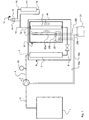
- FIG. 1 shows schematically a water supply system, for example for caravans, campers, boats, planes or any similar application, where the water for domestic purposes is carried in a storage tank 1.
- the water supply system comprises a pump 2, the suction side of which is connected to the storage tank 1 by a pipe 3.
- the pressure side of the pump 2 is connected via a pipe 4 to an inlet 5 of a water purifier 6.
- the water purifier 6 comprises a filter 7 which contains active carbon, a reducing valve 8 and a UV-light purifier 9 with a UV fluorescent tube 10 and a quartz glass tube 11, through which water is passed while it is illuminated by the UV light.
- An outlet 12 of the water purifier is connected to a cold water faucet 14 at a tapping point 15 via a pipe 13.
- the outlet 12 is also connected to a water heater 17 powered by electricity or bottled gas, which is connected to the hot water faucet 19 at the tapping point via a pipe 18.
- a pressure sensor 20 is connected to the liquid pipe 4 and arranged to detect the pressure in the water pipe between the pressure side of the pump 2 and the tapping point 15.
- the pressure sensor 20 can alternatively be connected to any other section of liquid pipe on the pressure side of the pump or to the pump 2 on its pressure side.
- a voltage source 21 in the form of a 12V DC battery is arranged to supply power to the pump 2 and the UV fluorescent tube 10 in the UV-light purifier 9.
- Electrical supply leads 22a, 22b connect the plus and minus poles respectively of the voltage source 21 to a circuit board 23 which is arranged in the UV-light purifier 9 for controlling the function of the system.
- electrical supply leads 24a, 24b are taken from the circuit board 23 to the supply connections of the pump 2.
- the UV fluorescent tube 10 is also electrically connected to the circuit board 23 by means of two supply leads 25a, 25b.
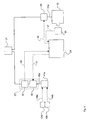
- FIG. 2 shows the function of the means for automatically lighting up the UV fluorescent tube when the pump is started.
- the pump 2 is connected by its positive supply lead 24a to the voltage source 21 via a pump switch 26 and an HSD 27.
- the UV fluorescent tube 10 is connected by its positive supply lead 25a to the voltage source 21 via a switch 28.
- a microprocessor 29 communicates with the HSD 27 and the switch 28. This communication is symbolized in the figure by the broken arrows 30 and 31, 32 respectively.
- the pressure sensor 20 is arranged in the liquid pipe 4 (see also Figure 1) and is electrically connected to the pump switch 26 for communication 33 with this.
- the HSD comprises functionally a current detector 34 and an emergency cut-out 35.
- the microprocessor can be programmed to switch off the UV fluorescent tube a certain time, for example 30-60 seconds, after the pump is switched off. If the user again draws off water from the system within this period of time, the UV fluorescent tube does not need to be switched off and lit up again, which prolongs its life, as each lighting up of the fluorescent tube shortens its life.
- the HSD 27 can also comprise an emergency cut-out function 35, which is used to switch off the pump 2 and thereby the UV fluorescent tube 10 if an abnormal operating situation arises.
- an abnormal operating situation can, for example, be that the light intensity from the UV fluorescent tube 10 is too low, so that an adequate destruction of micro-organisms can not be ensured.
- a low light intensity can in turn be due to the UV fluorescent tube 10 being worn out or can be due to deposits on the quartz glass tube 11.
- a light-intensity sensor 36 can be arranged in the UV-light purifier 9 on the opposite side of the quartz glass tube 11 to the UV fluorescent tube 10.
- the light-intensity sensor 36 detects that the UV light intensity is less than a certain predetermined level, the sensor 36 sends a signal 37 to the microprocessor 29, which then sends an order signal 31 to the HSD's 27 emergency cut-out function 35.
- the emergency cut-out 35 then breaks, whereupon the supply current of the pump 2 ceases to pass through the supply lead 24a, so that the pump 2 and hence the UV fluorescent tube 10 are switched off, as described above.
- a light-emitting diode can be connected to the microprocessor in order to give the user an indication that the system needs attention when the emergency cut-out function 35 operates.
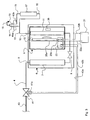
- Figures 3 and 4 show an alternative embodiment of the liquid supply system according to the invention, which can be used for stationary applications where there is access to a pressurized water supply network 40.
- the components and elements that are common to the embodiment described above have the same reference numbers in Figures 3 and 4 as in Figures 1 and 2. The description below deals principally with what distinguishes this embodiment from the embodiment described above.
- the liquid supply system is connected to the water supply network 40 by means of a flow regulator in the form of an electrically-controlled valve 41.
- the valve 41 is normally closed and is opened by means of a supply voltage being connected from the voltage source 21 via the circuit board 23 and the valve's electrical supply leads 42a, 42b to an electrical control device 41 a on the valve 41.
- Two microswitches 43a, 43b are mechanically connected to the cold 14 and hot water faucets 19 respectively at the tapping point.
- the microswitches 43a, 43b are electrically connected to the valve's electrical control device 41 a for communication 44a and 44b respectively with this.
- a user wants to draw off water from the liquid supply system, he or she opens one or both faucets 14, 19 at the tapping point 15, whereupon one or both of the microswitches 43a, 43b closes and sends a signal 44a, 44b respectively to the valve's control device 41 a.
- the control device 41 a is then activated, whereupon the valve 41 opens so that water flows through the liquid pipe 4 to the liquid purifier 6 and the tapping point 15, while at the same time a current starts to pass through the positive supply lead 42a of the control device 41 a.
- the supply current is detected by the HSD's 27 current detector 34, which thereupon sends a signal 30 to the microprocessor 29.
- the signal 30 causes the microprocessor 29 to send a signal 32 to the UV fluorescent tube's 10 switch 28 which closes, whereupon the UV fluorescent tube 10 is connected to the voltage source 21 and is lit up.
- the microswitches 43a, 43b are broken and thereby cease to send the signals 44a, 44b respectively to the valve's 41 control device 41 a which then closes the valve 41.
- the supply current to the control device 41 a then ceases, which is detected by the HSD 27, which communicates with the UV fluorescent tube's 10 switch 28 via the microprocessor 29, so that the UV fluorescent tube is switched off.
- the HSD can be replaced by a low side driver, which is connected to the negative supply lead of the pump or of the valve's control device.
- the means for automatically lighting up the UV light source when the pump starts can comprise a diode which is connected between the pump's negative or positive supply lead and earth.
- the flow regulator 2, 41 can consist of a manual switch which is suitably located in the vicinity of the tapping point.
- the choice of means for controlling the flow regulator is not dependent upon the type of flow regulator.
- a pump switch can be controlled by, or can consist of, a manual switch or one or microswitches that are mechanically connected to the faucets, and similarly an electrically-controlled valve can be controlled by a pressure sensor or by a manual switch.
- the system can also be used for other applications, such as stationary households, where the storage tank or water supply network can be replaced by, for example, a well.
- the signals can be achieved by the respective signal-transmitting component generating a high or a low voltage at its communication output, with the different voltage levels representing different instructions to the signal-receiving component.
- the voltage source consists suitably of a 9 V - 35 V, preferably a 12 V or 24 V DC voltage source but also other voltage sources such as a transformer or battery charger that is supplied with 100 - 240 V AC voltage, and which supplies 9 - 35 V DC voltage, can be used.
- the emergency cut-out function 35 can also be triggered as a result of order signals from the microprocessor, which are caused by other malfunctions than low UV light intensity. Examples of such malfunctions are too high a flow through the quartz glass tube, whereby adequate destruction of micro-organisms cannot be ensured, or too low a flow through the quartz glass tube which indicates that the filter is blocked.
Landscapes
- Life Sciences & Earth Sciences (AREA)
- Hydrology & Water Resources (AREA)
- Engineering & Computer Science (AREA)
- Environmental & Geological Engineering (AREA)
- Water Supply & Treatment (AREA)
- Chemical & Material Sciences (AREA)
- Organic Chemistry (AREA)
- Physical Water Treatments (AREA)
- Apparatus For Disinfection Or Sterilisation (AREA)
- Pipeline Systems (AREA)
- Fluid-Driven Valves (AREA)
- Sorption Type Refrigeration Machines (AREA)
Claims (10)
- System zum Liefern einer Flüssigkeit, aufweisend einen Entnahmepunkt (15) zum Entnehmen einer Flüssigkeit aus dem System, eine Flüssigkeitsleitung (4, 5, 12, 13, 16, 18), welche den Entnahmepunkt mit einem Strömungsregler (2, 41) verbindet, welcher in einem aktiven Modus die Flüssigkeit von einer Flüssigkeitsquelle (1, 40) durch die Leitung zu dem Entnahmepunkt passieren lässt und in einem inaktiven Modus die Strömung der Flüssigkeit durch die Flüssigkeitsleitung verhindert, einen Flüssigkeitsreiniger (6), welcher mit der Flüssigkeitsleitung zwischen dem Entnahmepunkt und dem Strömungsregler verbunden ist und welcher eine elektrische UV-Lichtquelle (10) und eine Einrichtung zum automatischen Einschalten der UV-Lichtquelle (10) aufweist, wenn der Strömungsregler (2, 40) aktiviert ist zum Passierenlassen der Flüssigkeit durch die Flüssigkeitsleitung und den Entnahmepunkt, dadurch gekennzeichnet, dass der Strömungsregler (2, 41) elektrisch gesteuert ist und mit einer Spannungsquelle (21) über eine elektrische Versorgungsleitung (24a, 24b, 42a, 42b) verbunden ist, und dass die Einrichtung zum automatischen Einschalten der UV-Lichtquelle (10) angeordnet ist, um einen Versorgungsstrom zu erfassen, der durch die Versorgungsleitung fließt, wenn der Strömungsregler aktiviert ist, und um die UV-Lichtquelle einzuschalten, wenn der Versorgungsstrom durch die Versorgungsleitung strömt.
- System nach Anspruch 1, bei welchem die Einrichtung zum automatischen Einschalten der UV-Lichtquelle (10) eine elektronische Steuerschaltung (27) aufweist, welche mit einer der elektrischen Versorgungsleitungen (24a, 24b, 42a, 42b) des Strömungsreglers (2, 40) und einem Mikroprozessor (29) verbunden ist, und bei welchem die elektronische Steuerschaltung angeordnet ist, um ein Betriebssignal (30) zu senden, wenn der Strömungsregler (2, 40) aktiviert ist, woraufhin ein Versorgungsstrom durch die Versorgungsleitung des Strömungsreglers fließt, und der Mikroprozessor angeordnet ist, um das Betriebssignal zu erfassen und die UV-Lichtquelle einzuschalten durch Verbinden der UV-Lichtquelle mit der Spannungsquelle (21), wenn die Steuerschaltung das Betriebssignal sendet.
- System nach Anspruch 2, bei welchem die elektronische Steuerschaltung (27) einen Einrichtung (35) zum Unterbrechen des Versorgungsstroms zu dem Strömungsregler (2, 40) als Ergebnis eines Befehlssignals (31) von dem Mikroprozessor (29) aufweist.
- System nach Anspruch 3 oder 4, bei welchem die elektronische Steuerschaltung einen so genannten Hochseiten-Treiber (27) aufweist.
- System nach Anspruch 1, bei welchem eine Diode zwischen einer der Versorgungsleitungen des Strömungsreglers und Masse verbunden ist und bei welchem ein Mikroprozessor angeordnet ist, um einen Spannungsabfall über der Diode zu erfassen, wenn der Strömungsregler aktiviert ist, und um die UV-Lichtquelle mit der Spannungsquelle zu verbinden, wenn der Mikroprozessor den Spannungsabfall über der Diode erfasst.
- System nach irgendeinem der Ansprüche 1 bis 5, bei welchem der Strömungsregler aus einer elektrischen Flüssigkeitspumpe (2) besteht, welche durch einen Pumpenschalter (26) gesteuert ist, welcher auf einer der elektrischen Versorgungsleitungen (24a, 24b) der Pumpe angeordnet ist.
- System nach irgendeinem der Ansprüche 1 bis 5, bei welchem der Strömungsregler aus einem elektrisch gesteuerten Ventil (41) besteht, welches eine elektrische Steuervorrichtung (41a) aufweist, wobei das Ventil normalerweise geschlossen ist und geöffnet ist, wenn die Steuervorrichtung aktiviert ist durch Passierenlassen eines Versorgungsstromes durch die elektrischen Versorgungsleitungen (42a, 42b) der Steuervorrichtung.
- System nach irgendeinem der Ansprüche 6 oder 7, bei welchem ein Drucksensor (28) in der Flüssigkeitsleitung (4, 5, 11, 12, 13, 16, 18) oder in dem Strömungsregler (2, 40) angeordnet ist und mit dem Pumpenschalter (26) oder der elektrischen Steuervorrichtung (41a) des Ventils (41) verbunden ist, so dass der Strömungsregler aktiviert ist, wenn der Druck in der Flüssigkeitsleitung kleiner als ein vorbestimmtes Niveau ist.
- System nach irgendeinem der Ansprüche 1 bis 8, bei welchem der Strömungsregler (2, 40) und die UV-Lichtquelle mit ein und derselben Spannungsquelle (21) verbunden sind.
- System nach irgendeinem der Ansprüche 1 bis 9, bei welchem die Spannungsquelle (17) eine 12 V Gleichstromspannungsquelle ist.
Applications Claiming Priority (3)
| Application Number | Priority Date | Filing Date | Title |
|---|---|---|---|
| SE0203469 | 2002-11-22 | ||
| SE0203469A SE526093C2 (sv) | 2002-11-22 | 2002-11-22 | System för vätskeförsörjning |
| PCT/SE2003/001803 WO2004048275A1 (en) | 2002-11-22 | 2003-11-20 | System for supply of liquid |
Publications (2)
| Publication Number | Publication Date |
|---|---|
| EP1562865A1 EP1562865A1 (de) | 2005-08-17 |
| EP1562865B1 true EP1562865B1 (de) | 2006-10-11 |
Family
ID=20289656
Family Applications (1)
| Application Number | Title | Priority Date | Filing Date |
|---|---|---|---|
| EP03774426A Expired - Lifetime EP1562865B1 (de) | 2002-11-22 | 2003-11-20 | System zur zufuhr von flüssigkeit |
Country Status (7)
| Country | Link |
|---|---|
| US (1) | US20060124861A1 (de) |
| EP (1) | EP1562865B1 (de) |
| AT (1) | ATE342235T1 (de) |
| AU (1) | AU2003284828A1 (de) |
| DE (1) | DE60309064D1 (de) |
| SE (1) | SE526093C2 (de) |
| WO (1) | WO2004048275A1 (de) |
Cited By (2)
| Publication number | Priority date | Publication date | Assignee | Title |
|---|---|---|---|---|
| EP2559668A1 (de) | 2011-08-16 | 2013-02-20 | BSH Bosch und Siemens Hausgeräte GmbH | Wasserbereiter |
| US10180248B2 (en) | 2015-09-02 | 2019-01-15 | ProPhotonix Limited | LED lamp with sensing capabilities |
Families Citing this family (6)
| Publication number | Priority date | Publication date | Assignee | Title |
|---|---|---|---|---|
| CN1977978B (zh) * | 2005-12-01 | 2011-07-06 | 福建新大陆环保科技有限公司 | 一种开放式水渠辐射消毒系统 |
| US20140021220A1 (en) * | 2009-07-09 | 2014-01-23 | James W. Windham | Water generator utilizing an air conditioner system |
| US9764967B1 (en) * | 2013-02-20 | 2017-09-19 | Charles E. Hill & Associates, Inc. | Sanitizing system and method for a septic system |
| DE102015118175A1 (de) * | 2015-10-23 | 2017-04-27 | Marc Breit | Vorrichtung zur Emission elektromagnetischer Strahlung, insbesondere UV-Strahlung |
| US20180362367A1 (en) * | 2015-12-11 | 2018-12-20 | Orbital Systems Ab | An apparatus for water supply and sanitary purposes |
| WO2018097789A1 (en) * | 2016-11-25 | 2018-05-31 | Orbital Systems Ab | Sensor system for a system allowing for purification and recycling of water or separation of water |
Family Cites Families (19)
| Publication number | Priority date | Publication date | Assignee | Title |
|---|---|---|---|---|
| US3844741A (en) * | 1972-10-11 | 1974-10-29 | P Dimitrik | Air purifier |
| US3948772A (en) * | 1975-04-16 | 1976-04-06 | Sidney Ellner | Split stream ultraviolet purification device |
| FR2500430A1 (fr) * | 1981-02-26 | 1982-08-27 | Commissariat Energie Atomique | Dispositif pour la purification de l'eau |
| US4535247A (en) * | 1983-07-11 | 1985-08-13 | Kurtz Mark E | Water sterilization system |
| US4757205A (en) * | 1986-06-10 | 1988-07-12 | Arlat Inc. | Ultraviolet water treatment apparatus |
| US4825083A (en) * | 1986-06-10 | 1989-04-25 | Arlat Inc. | Ultraviolet water treatment apparatus |
| US4909931A (en) * | 1987-12-17 | 1990-03-20 | Tana - Netiv Halamed-He Industries | Water-purifier device |
| US5401394A (en) * | 1993-01-11 | 1995-03-28 | Amway Corporation | Water treatment system ultraviolet bulb voltage monitor circuit |
| US5536395A (en) * | 1993-03-22 | 1996-07-16 | Amway Corporation | Home water purification system with automatic disconnecting of radiant energy source |
| US5547590A (en) * | 1994-09-19 | 1996-08-20 | Szabo; Louis | UV-based water decontamination system with dimmer-control |
| US5780860A (en) * | 1995-09-08 | 1998-07-14 | The Regents Of The University Of California | UV water disinfector |
| US5785845A (en) * | 1995-11-09 | 1998-07-28 | Colaiano; Robert | Water purifying system |
| US5709799A (en) * | 1996-06-03 | 1998-01-20 | Vortex Corporation | Super ozonating water purifier |
| US6117335A (en) * | 1998-02-23 | 2000-09-12 | New Star Lasers, Inc. | Decontamination of water by photolytic oxidation/reduction utilizing near blackbody radiation |
| AU5032700A (en) * | 1999-05-21 | 2000-12-12 | Life Spring Limited Partnership | User-activated ultra-violet water treatment unit |
| US6451202B1 (en) * | 1999-06-21 | 2002-09-17 | Access Business Group International Llc | Point-of-use water treatment system |
| US6669838B1 (en) * | 1999-06-21 | 2003-12-30 | Access Business Group International Llc. | Apparatus for filtering and sterilizing water utilizing a turbidity and microorganism sensing system |
| US6453799B1 (en) * | 2000-11-14 | 2002-09-24 | Ecoaid Corp. | Automatic vending machine with functional water generator |
| US7306716B2 (en) * | 2004-06-16 | 2007-12-11 | Access Business Group International Llc | Water treatment system |
-
2002
- 2002-11-22 SE SE0203469A patent/SE526093C2/sv not_active IP Right Cessation
-
2003
- 2003-11-20 US US10/535,275 patent/US20060124861A1/en not_active Abandoned
- 2003-11-20 WO PCT/SE2003/001803 patent/WO2004048275A1/en not_active Ceased
- 2003-11-20 AU AU2003284828A patent/AU2003284828A1/en not_active Abandoned
- 2003-11-20 DE DE60309064T patent/DE60309064D1/de not_active Expired - Fee Related
- 2003-11-20 AT AT03774426T patent/ATE342235T1/de not_active IP Right Cessation
- 2003-11-20 EP EP03774426A patent/EP1562865B1/de not_active Expired - Lifetime
Cited By (3)
| Publication number | Priority date | Publication date | Assignee | Title |
|---|---|---|---|---|
| EP2559668A1 (de) | 2011-08-16 | 2013-02-20 | BSH Bosch und Siemens Hausgeräte GmbH | Wasserbereiter |
| DE102011081054A1 (de) | 2011-08-16 | 2013-02-21 | BSH Bosch und Siemens Hausgeräte GmbH | Wasserbereiter |
| US10180248B2 (en) | 2015-09-02 | 2019-01-15 | ProPhotonix Limited | LED lamp with sensing capabilities |
Also Published As
| Publication number | Publication date |
|---|---|
| SE526093C2 (sv) | 2005-07-05 |
| DE60309064D1 (de) | 2006-11-23 |
| WO2004048275A1 (en) | 2004-06-10 |
| ATE342235T1 (de) | 2006-11-15 |
| EP1562865A1 (de) | 2005-08-17 |
| SE0203469D0 (sv) | 2002-11-22 |
| US20060124861A1 (en) | 2006-06-15 |
| AU2003284828A1 (en) | 2004-06-18 |
| SE0203469L (sv) | 2004-07-14 |
Similar Documents
| Publication | Publication Date | Title |
|---|---|---|
| CN100508683C (zh) | 具有紫外灯和水流动指示器部件的水处理系统的电镇流器 | |
| US9709054B2 (en) | Test and monitoring system for a pump installation | |
| US9528522B2 (en) | Test and monitoring system for a sump pump installation having a self-monitoring valve module for admitting water to the sump pit | |
| US9528512B2 (en) | Test and monitoring system for a battery-powered DC pump installation | |
| US9528523B2 (en) | Test and monitoring system for a sump pump installation having a variable test cycle time out | |
| US9534593B2 (en) | Test and monitoring system for a sump pump installation operable from a remote location | |
| US9523366B2 (en) | Test and monitoring system for a sump pump installation having a self-protecting valve assembly for admitting water to the sump container | |
| US9528873B2 (en) | Test and monitoring system for a sump pump installation having a self-monitoring liquid level sensing module | |
| US9534606B2 (en) | Test and monitoring system for a sump pump installation including trend analysis of pump performance | |
| JP3238818B2 (ja) | 浄水器、及びこれに用いられる電気回路 | |
| KR20030077943A (ko) | 언더카운터 수처리 시스템 | |
| US7175760B2 (en) | Water dispensing apparatus with water recirculation line | |
| US20060124861A1 (en) | System for supply of liquid | |
| AU2018204725B2 (en) | Test and monitoring system for a dual sump pump installation | |
| CN106830396A (zh) | 净饮机 | |
| EP1562863B1 (de) | Verfahren und vorrichtung zur reinigungeiner fl ssigkeit | |
| CN206666246U (zh) | 净饮机 | |
| US8292618B2 (en) | Dental unit and method for feeding water | |
| CA2931194C (en) | Test and monitoring system for a sump pump installation having a self-monitoring valve module for admitting water to the sump pit | |
| KR200301154Y1 (ko) | 이온수 제조가 가능한 냉온정수기 | |
| JP2002322700A (ja) | オゾン水供給装置 | |
| JPS63129180A (ja) | ポンプの自動運転装置 | |
| JP2003119853A (ja) | 自動水栓 |
Legal Events
| Date | Code | Title | Description |
|---|---|---|---|
| PUAI | Public reference made under article 153(3) epc to a published international application that has entered the european phase |
Free format text: ORIGINAL CODE: 0009012 |
|
| 17P | Request for examination filed |
Effective date: 20050507 |
|
| AK | Designated contracting states |
Kind code of ref document: A1 Designated state(s): AT BE BG CH CY CZ DE DK EE ES FI FR GB GR HU IE IT LI LU MC NL PT RO SE SI SK |
|
| AX | Request for extension of the european patent |
Extension state: AL LT LV MK |
|
| DAX | Request for extension of the european patent (deleted) | ||
| GRAP | Despatch of communication of intention to grant a patent |
Free format text: ORIGINAL CODE: EPIDOSNIGR1 |
|
| GRAS | Grant fee paid |
Free format text: ORIGINAL CODE: EPIDOSNIGR3 |
|
| GRAA | (expected) grant |
Free format text: ORIGINAL CODE: 0009210 |
|
| AK | Designated contracting states |
Kind code of ref document: B1 Designated state(s): AT BE BG CH CY CZ DE DK EE ES FI FR GB GR HU IE IT LI LU MC NL PT RO SE SI SK |
|
| PG25 | Lapsed in a contracting state [announced via postgrant information from national office to epo] |
Ref country code: IT Free format text: LAPSE BECAUSE OF FAILURE TO SUBMIT A TRANSLATION OF THE DESCRIPTION OR TO PAY THE FEE WITHIN THE PRESCRIBED TIME-LIMIT;WARNING: LAPSES OF ITALIAN PATENTS WITH EFFECTIVE DATE BEFORE 2007 MAY HAVE OCCURRED AT ANY TIME BEFORE 2007. THE CORRECT EFFECTIVE DATE MAY BE DIFFERENT FROM THE ONE RECORDED. Effective date: 20061011 Ref country code: SI Free format text: LAPSE BECAUSE OF FAILURE TO SUBMIT A TRANSLATION OF THE DESCRIPTION OR TO PAY THE FEE WITHIN THE PRESCRIBED TIME-LIMIT Effective date: 20061011 Ref country code: SK Free format text: LAPSE BECAUSE OF FAILURE TO SUBMIT A TRANSLATION OF THE DESCRIPTION OR TO PAY THE FEE WITHIN THE PRESCRIBED TIME-LIMIT Effective date: 20061011 Ref country code: RO Free format text: LAPSE BECAUSE OF FAILURE TO SUBMIT A TRANSLATION OF THE DESCRIPTION OR TO PAY THE FEE WITHIN THE PRESCRIBED TIME-LIMIT Effective date: 20061011 Ref country code: AT Free format text: LAPSE BECAUSE OF FAILURE TO SUBMIT A TRANSLATION OF THE DESCRIPTION OR TO PAY THE FEE WITHIN THE PRESCRIBED TIME-LIMIT Effective date: 20061011 Ref country code: FI Free format text: LAPSE BECAUSE OF FAILURE TO SUBMIT A TRANSLATION OF THE DESCRIPTION OR TO PAY THE FEE WITHIN THE PRESCRIBED TIME-LIMIT Effective date: 20061011 Ref country code: NL Free format text: LAPSE BECAUSE OF FAILURE TO SUBMIT A TRANSLATION OF THE DESCRIPTION OR TO PAY THE FEE WITHIN THE PRESCRIBED TIME-LIMIT Effective date: 20061011 Ref country code: LI Free format text: LAPSE BECAUSE OF FAILURE TO SUBMIT A TRANSLATION OF THE DESCRIPTION OR TO PAY THE FEE WITHIN THE PRESCRIBED TIME-LIMIT Effective date: 20061011 Ref country code: CZ Free format text: LAPSE BECAUSE OF FAILURE TO SUBMIT A TRANSLATION OF THE DESCRIPTION OR TO PAY THE FEE WITHIN THE PRESCRIBED TIME-LIMIT Effective date: 20061011 Ref country code: BE Free format text: LAPSE BECAUSE OF FAILURE TO SUBMIT A TRANSLATION OF THE DESCRIPTION OR TO PAY THE FEE WITHIN THE PRESCRIBED TIME-LIMIT Effective date: 20061011 Ref country code: CH Free format text: LAPSE BECAUSE OF FAILURE TO SUBMIT A TRANSLATION OF THE DESCRIPTION OR TO PAY THE FEE WITHIN THE PRESCRIBED TIME-LIMIT Effective date: 20061011 |
|
| REG | Reference to a national code |
Ref country code: GB Ref legal event code: FG4D |
|
| RIN1 | Information on inventor provided before grant (corrected) |
Inventor name: HEGMEGI, ZSOLT |
|
| REG | Reference to a national code |
Ref country code: CH Ref legal event code: EP |
|
| REG | Reference to a national code |
Ref country code: IE Ref legal event code: FG4D |
|
| PG25 | Lapsed in a contracting state [announced via postgrant information from national office to epo] |
Ref country code: IE Free format text: LAPSE BECAUSE OF NON-PAYMENT OF DUE FEES Effective date: 20061120 |
|
| REF | Corresponds to: |
Ref document number: 60309064 Country of ref document: DE Date of ref document: 20061123 Kind code of ref document: P |
|
| PG25 | Lapsed in a contracting state [announced via postgrant information from national office to epo] |
Ref country code: MC Free format text: LAPSE BECAUSE OF NON-PAYMENT OF DUE FEES Effective date: 20061130 |
|
| PG25 | Lapsed in a contracting state [announced via postgrant information from national office to epo] |
Ref country code: SE Free format text: LAPSE BECAUSE OF FAILURE TO SUBMIT A TRANSLATION OF THE DESCRIPTION OR TO PAY THE FEE WITHIN THE PRESCRIBED TIME-LIMIT Effective date: 20070111 Ref country code: DK Free format text: LAPSE BECAUSE OF FAILURE TO SUBMIT A TRANSLATION OF THE DESCRIPTION OR TO PAY THE FEE WITHIN THE PRESCRIBED TIME-LIMIT Effective date: 20070111 Ref country code: BG Free format text: LAPSE BECAUSE OF FAILURE TO SUBMIT A TRANSLATION OF THE DESCRIPTION OR TO PAY THE FEE WITHIN THE PRESCRIBED TIME-LIMIT Effective date: 20070111 |
|
| PG25 | Lapsed in a contracting state [announced via postgrant information from national office to epo] |
Ref country code: ES Free format text: LAPSE BECAUSE OF FAILURE TO SUBMIT A TRANSLATION OF THE DESCRIPTION OR TO PAY THE FEE WITHIN THE PRESCRIBED TIME-LIMIT Effective date: 20070122 |
|
| PG25 | Lapsed in a contracting state [announced via postgrant information from national office to epo] |
Ref country code: PT Free format text: LAPSE BECAUSE OF FAILURE TO SUBMIT A TRANSLATION OF THE DESCRIPTION OR TO PAY THE FEE WITHIN THE PRESCRIBED TIME-LIMIT Effective date: 20070319 |
|
| NLV1 | Nl: lapsed or annulled due to failure to fulfill the requirements of art. 29p and 29m of the patents act | ||
| REG | Reference to a national code |
Ref country code: CH Ref legal event code: PL |
|
| EN | Fr: translation not filed | ||
| PG25 | Lapsed in a contracting state [announced via postgrant information from national office to epo] |
Ref country code: DE Free format text: LAPSE BECAUSE OF NON-PAYMENT OF DUE FEES Effective date: 20070601 |
|
| PLBE | No opposition filed within time limit |
Free format text: ORIGINAL CODE: 0009261 |
|
| STAA | Information on the status of an ep patent application or granted ep patent |
Free format text: STATUS: NO OPPOSITION FILED WITHIN TIME LIMIT |
|
| 26N | No opposition filed |
Effective date: 20070712 |
|
| PG25 | Lapsed in a contracting state [announced via postgrant information from national office to epo] |
Ref country code: GR Free format text: LAPSE BECAUSE OF FAILURE TO SUBMIT A TRANSLATION OF THE DESCRIPTION OR TO PAY THE FEE WITHIN THE PRESCRIBED TIME-LIMIT Effective date: 20070112 Ref country code: FR Free format text: LAPSE BECAUSE OF FAILURE TO SUBMIT A TRANSLATION OF THE DESCRIPTION OR TO PAY THE FEE WITHIN THE PRESCRIBED TIME-LIMIT Effective date: 20070601 |
|
| PG25 | Lapsed in a contracting state [announced via postgrant information from national office to epo] |
Ref country code: EE Free format text: LAPSE BECAUSE OF FAILURE TO SUBMIT A TRANSLATION OF THE DESCRIPTION OR TO PAY THE FEE WITHIN THE PRESCRIBED TIME-LIMIT Effective date: 20061011 |
|
| GBPC | Gb: european patent ceased through non-payment of renewal fee |
Effective date: 20071120 |
|
| PG25 | Lapsed in a contracting state [announced via postgrant information from national office to epo] |
Ref country code: LU Free format text: LAPSE BECAUSE OF NON-PAYMENT OF DUE FEES Effective date: 20061120 Ref country code: HU Free format text: LAPSE BECAUSE OF FAILURE TO SUBMIT A TRANSLATION OF THE DESCRIPTION OR TO PAY THE FEE WITHIN THE PRESCRIBED TIME-LIMIT Effective date: 20070412 |
|
| PG25 | Lapsed in a contracting state [announced via postgrant information from national office to epo] |
Ref country code: FR Free format text: LAPSE BECAUSE OF FAILURE TO SUBMIT A TRANSLATION OF THE DESCRIPTION OR TO PAY THE FEE WITHIN THE PRESCRIBED TIME-LIMIT Effective date: 20061011 Ref country code: CY Free format text: LAPSE BECAUSE OF FAILURE TO SUBMIT A TRANSLATION OF THE DESCRIPTION OR TO PAY THE FEE WITHIN THE PRESCRIBED TIME-LIMIT Effective date: 20061011 |
|
| PG25 | Lapsed in a contracting state [announced via postgrant information from national office to epo] |
Ref country code: GB Free format text: LAPSE BECAUSE OF NON-PAYMENT OF DUE FEES Effective date: 20071120 |