EP1563134B1 - Dispositif de traitement d'articles en forme de bande par ecoulement et application de pression - Google Patents
Dispositif de traitement d'articles en forme de bande par ecoulement et application de pression Download PDFInfo
- Publication number
- EP1563134B1 EP1563134B1 EP03796001A EP03796001A EP1563134B1 EP 1563134 B1 EP1563134 B1 EP 1563134B1 EP 03796001 A EP03796001 A EP 03796001A EP 03796001 A EP03796001 A EP 03796001A EP 1563134 B1 EP1563134 B1 EP 1563134B1
- Authority
- EP
- European Patent Office
- Prior art keywords
- sheet
- metal
- drum
- rings
- strips
- Prior art date
- Legal status (The legal status is an assumption and is not a legal conclusion. Google has not performed a legal analysis and makes no representation as to the accuracy of the status listed.)
- Expired - Lifetime
Links
Images


Classifications
-
- F—MECHANICAL ENGINEERING; LIGHTING; HEATING; WEAPONS; BLASTING
- F26—DRYING
- F26B—DRYING SOLID MATERIALS OR OBJECTS BY REMOVING LIQUID THEREFROM
- F26B13/00—Machines and apparatus for drying fabrics, fibres, yarns, or other materials in long lengths, with progressive movement
- F26B13/10—Arrangements for feeding, heating or supporting materials; Controlling movement, tension or position of materials
- F26B13/14—Rollers, drums, cylinders; Arrangement of drives, supports, bearings, cleaning
- F26B13/16—Rollers, drums, cylinders; Arrangement of drives, supports, bearings, cleaning perforated in combination with hot air blowing or suction devices, e.g. sieve drum dryers
-
- D—TEXTILES; PAPER
- D06—TREATMENT OF TEXTILES OR THE LIKE; LAUNDERING; FLEXIBLE MATERIALS NOT OTHERWISE PROVIDED FOR
- D06B—TREATING TEXTILE MATERIALS USING LIQUIDS, GASES OR VAPOURS
- D06B23/00—Component parts, details, or accessories of apparatus or machines, specially adapted for the treating of textile materials, not restricted to a particular kind of apparatus, provided for in groups D06B1/00 - D06B21/00
- D06B23/02—Rollers
- D06B23/025—Perforated rollers
-
- D—TEXTILES; PAPER
- D21—PAPER-MAKING; PRODUCTION OF CELLULOSE
- D21F—PAPER-MAKING MACHINES; METHODS OF PRODUCING PAPER THEREON
- D21F1/00—Wet end of machines for making continuous webs of paper
- D21F1/60—Cylinder moulds
-
- D—TEXTILES; PAPER
- D21—PAPER-MAKING; PRODUCTION OF CELLULOSE
- D21F—PAPER-MAKING MACHINES; METHODS OF PRODUCING PAPER THEREON
- D21F3/00—Press section of machines for making continuous webs of paper
- D21F3/02—Wet presses
- D21F3/10—Suction rolls, e.g. couch rolls
- D21F3/105—Covers thereof
-
- D—TEXTILES; PAPER
- D21—PAPER-MAKING; PRODUCTION OF CELLULOSE
- D21F—PAPER-MAKING MACHINES; METHODS OF PRODUCING PAPER THEREON
- D21F5/00—Dryer section of machines for making continuous webs of paper
- D21F5/18—Drying webs by hot air
- D21F5/182—Drying webs by hot air through perforated cylinders
- D21F5/184—Surfaces thereof
Definitions
- drum shell construction according to DE-A-100 01 535 is known in which to form the drum shell between the bottoms of the drum sheet strips unbent straight from floor to floor extend straight, the width of which extend substantially in the radial direction, and between the metal strips evenly distributed over the length of the drum held on the metal strip metal rings are arranged, sheet metal strips and metal rings are pushed into one another and both the metal strips and the metal rings are provided with radially directed insertion slots.
- the previously known shell construction of a permeable drum is preferably provided for the hydrodynamic needling of nonwovens and the like.
- Hard water jets shoot against the drum only along a drum sheath line, but in any case, surface loading does not occur over the circumference of the drum. Therefore, it is less disturbing that this sheath structure is unstable.
- a cladding structure is to be used for heat-treating textile goods, wherein the textile material, nonwoven, tissue or paper rests on the drum over a larger lateral surface for surface treatment and a gaseous treatment agent circulated in the device is applied under surface pressure, this labile design is not more suitable.
- EP-A-0 315 961 according to which integral connecting elements are arranged between the longitudinally extending metal strips, the corresponding distance to the desired distance of the immediately adjacent metal strips formed and fixed on both sides with the adjacent metal strip by means of a screw are connected.
- This shell structure also has a maximum open shell surface, it is also solid and permanently stable, but also expensive to manufacture.
- a perforated screen drum is arranged radially inwardly under said open shell construction, but there because of the air resistance generated to achieve a uniform flow through the web over the working width is used.
- a simpler and thus cheaper shell structure EP-A-0 753 619 according to the between the screen covering and the drum shell as a substructure to increase the distance between a screen drum and the screen lining alone in parallel over the entire length of the drum from floor to floor straight extending, U-shaped bent sheet metal strips are arranged at a distance from each other, whose respective bottom is bolted to the metal drum jacket.
- This jacket construction ensures a high air permeability for the textile and also generates a sufficient back pressure outside the drum due to the perforated screen drum, but it is not guaranteed the required Beulsteifmaschine the screen drum at high air pressure loads of the drum.
- the actually only normally perforated drum casing is subjected to a high load fluctuation in the region of the change between the region in which the material web rests on the drum and is aerated due to the air pressure and the region where the inner cover covers the drum casing against the air pressure. which causes a deformation of the drum, which makes the drum out of round.
- the sheet metal strips extending straight from floor to floor should be provided with no slots at their edge arranged radially on the outside, because at least on this edge the screen mesh rests on and is therefore supported uninterruptedly over the entire length of the drum.
- the metal rings must be provided on their radial outer edge with the appropriate insertion slots.
- the radial height of the metal strips and rings may be the same, but it is better to make the metal rings smaller by a small amount, so that the mesh only rests on the outer edges of the metal strip. Accordingly, the slot depths are to be introduced into the strips and rings.
- the length of the slots should also be such that the metal strips remain as undiminished as possible in their rigidity, so the slots are dimensioned at their lower edge only slightly in length, while then the corresponding slots of the metal rings must be longer.
- the consequent reduction in the stability of the rings is irrelevant, since these rings are only useful for the round stiffness of the drum, while the strips additionally have to carry the web under air pressure.
- the outer edges of the metal strips so wear the screen fabric on which the textile to be treated od. Like. Rests. It is expedient to at least deburr the two longitudinal edges of the outer edge of the metal strips, to round better, in order to avoid unnecessary destructive friction between the mesh and the support. However, this rounding processing of the longitudinal edges is very expensive, which is why the invention further proposes to produce the metal strips of the drum from a bent sheet whose bending edge the outer edge of the sheet metal strip forms. The two flanges of the bent sheet should be firmly together, which also increases the rigidity and stability of the drum as a whole.
- the existing of the bolted metal strip construction jacket of the screening drum is stable in bending over its entire surface. However, it may be necessary for reasons of uniform distribution of the supplied air to create a dynamic pressure on the outside of the drum. This is of course already produced by the upstream screening deck, but it is better, as in EP-A-0 678 613, to arrange a perforated screening drum radially below the sheet-metal strip structure, on which the sheet-metal strip structure is then supported. However, this should also be bolted to the screen drum, for which individual rectangular metal bracket are advantageous.
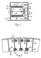
- a screen drum device for heat treatment basically consists of an approximately rectangular housing 1, which is divided by an intermediate wall 2 into a treatment space 3 and a fan space 4.
- the air-permeable drum 5 and concentrically to this in the fan chamber 4, a fan 6 is rotatably mounted.
- the fan room can also be arranged in a separated from the drum housing 1, not shown here, separate fan housing.
- the fan sets the interior of the drum 5 under induced draft and gives the heated air over a screen cover 7, which serves as a stowage deck, evenly distributed over the drum length in the treatment room.
- the new drum construction is also on a wet treatment device, which can also serve only for the suction of liquid, the subject of the patent.
- the overall construction is then adjusted accordingly.
- heating units 8 are arranged above and below the fan 6 and consist of pipes through which heating medium flows.
- the drum is covered in the area not covered by the textile material 9 inside of a down here arranged inner cover 10 against the induced draft.
- the supporting shell of the drum 5 is formed by the sheet metal strip structure 11 described below. This is wrapped on the outside by a fine mesh screen 12, which is held taut on the end faces of the drum, on the two floors 13, 14.
- the textile material to be treated 9 is under a pressure load generated by the accelerated air.
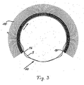
- the pressure load 15 acting around the drum is shown schematically in FIG.
- the textile material 9 since the textile material 9 only partially covers the circumference of the drum 5, in the area 10 in which the drum 5 is not covered by the textile material, it is covered from the inside, consequently no effective air pressure acts there on the casing, as shown in FIG. 3 is shown.
- This due to the rotation of the drum resulting load changes in particular at the beginning 16 of the inner cover and at the end 17 causes a change in the concentricity of the drum shell at least permanently.
- the drum 5 of Fig. 4 has a small diameter relative to its length. This is different when it comes to a construction for the heat treatment of a web.
- the drum 5 consists of a rigid sheet-metal strip construction, which consists of the sheet metal rings 18 of FIG. 5 and over the entire length of the drum extending sheet metal strip 19 of FIG.
- the thickness of the sheets for the sheet metal rings and metal strips may be 4 or even 5 mm and their spacing 40 mm or more. The dimensions depend on the desired and necessary stability of the roller.
- the sheet metal strips 19 are arranged at the same radial height as the sheet metal rings 18, the outer edges 20 and 21 thus form the outer circumferential surface of the drum and carry the screen fabric 12, which is shown on the left in Fig. 4 in plan view.
- the metal rings 18 have radially outward individual with uniform spacing from each other arranged insertion slots 25 which are aligned exactly radially.
- the width of the insertion slots corresponds to the cross section of the metal strips 19, so that the metal strips are inserted into the rings and thus held firmly in the sheet metal rings.
- the metal strips 19 of FIG. 6 have radially inwardly corresponding insertion slots 26 at a constant distance, which are introduced at right angles to the edge 20 of the metal strip 19.
- the width of these insertion slots 26 corresponds to the cross section of the metal rings 18, so that the metal strips 19 shown in FIG. 7 to the outer edge 21 of the metal rings 18 can be introduced and thus firmly held in the metal rings 18.
- the radial depth of the insertion slots 25 and 26 is approximately half the radial height of the strips 19 and rings 18, so that both the outer as well as the inner surface of the drum construction is formed by two intersecting plates.
- the inner surface of the drum can also be formed only by the rings 18, while the outer surface can be formed with advantage only by the metal strip 19.
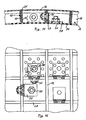
- FIG. 8 corresponds to that according to FIG. 2, only with the difference that the sheet-metal strip structure 11 according to FIG. 2 is a stable, self-supporting construction.
- each of the metal strips 19 in the region of their slots arranged below 26, to the flanks 26 ', 26 "of the slots 26 are mechanically connected by the material of the metal rings 18. This could of course also be done by means of welds, but these would be because of When the heat generated during welding changes the structure of the material of the strips, the drums would warp in.
- connection tabs 27, 31 are provided, which in the region of the respective slots 25, 26 are the flanks 25 ', 25 "and 26', 26" of FIG Since the respective wall of the adjacent strip is in the way for this purpose, an opening 28, 29 through which the connecting straps 27, 31 are slidable must be cut in this wall. 2 and the openings 28 in the sheet-metal strip 19 can be seen from Fig. 9. They are always introduced so that the mechanical tab connection to the outer Heen ends of the slots 25, 26 can take place. In this respect, as shown in FIG. 2, the radially inner slots 26 of the metal strip 19 are anchored by tabs 27 with screws 30. In contrast, as shown in FIG.
- the bolt of the screw 32 is provided with an eccentric 32 ', so that when not yet tightened screw 32, when the screw head of the screw 32 is rotated, the flanges 25 ', 25 "can be pulled against each other and aligned in parallel by means of the eccentric 32. This applies in particular to the longer slots 25 in the sheet metal rings 18.
- Fig. 11 corresponds to the illustration in Fig. 2.
- the connection of the metal strip with the metal rings is omitted there.
- a further perforated screening drum 34 is provided in addition to the sheet-metal strip structure 11, which rests radially inwards of the sheet-metal strip structure 11 directly against the lower edges of the sheet-metal strips 19.
- the angle iron 37 are also perforated to the air flow, as is apparent from Fig. 11, reference numeral 38.
- Fig. 11 discloses still a different construction of the sheet metal stiffeners. These are formed from a bent sheet, in such a way that the two flanges 39, 40 bent against each other by 180 ° against each other firmly, and together form the radially outwardly due to the bend rounded sheet metal strip 41. This has the advantage of greater stability of the possibly made of a thinner sheet metal strip 41, but he also has a round upper outer edge 20 'for the wear-free edition of the mesh fabric 12.
Landscapes
- Engineering & Computer Science (AREA)
- Textile Engineering (AREA)
- Mechanical Engineering (AREA)
- General Engineering & Computer Science (AREA)
- Treatment Of Fiber Materials (AREA)
- Paper (AREA)
- Current-Collector Devices For Electrically Propelled Vehicles (AREA)
- Connection Of Plates (AREA)
Claims (21)
- Dispositif de traitement par écoulement ou par projection de produits textiles, non-tissés, papier essuie-tout ou papier à l'aide d'un produit de traitement gazeux ou liquide, tournant éventuellement aussi dans le dispositif, comportant un tambour perméable sous traction d'aspiration présentant des fonds du côté frontal, qui sert d'élément de transport et de soutien de la matière et qui est recouvert à cet effet sur sa circonférence d'un revêtement de type tamis, tandis que, pour constituer la chemise du tambour, entre les fonds du tambour, des bandes de tôle non courbées s'étendent en ligne droite entre les fonds du tambour d'un fond à un autre, bandes dont l'extension en largeur s'étend sensiblement dans le sens radial et que des anneaux de tôle répartis régulièrement entre les bandes de tôle sont disposés sur la longueur du tambour et maintenus sur les bandes de tôle, les bandes de tôle et les anneaux de tôle pouvant être emboîtés les uns dans les autres et aussi bien les bandes de tôle que les anneaux de tôle présentant à cet effet des fentes d'insertion orientées radialement, caractérisé en ce que les flancs libres (25', 25", 26', 26'') des fentes d'insertion (25, 26) des bandes de tôle (19, 41) et également l'anneau de tôle (18) sont reliés fixement entre eux par au moins respectivement une bride de liaison supplémentaire (27, 31).
- Dispositif selon la revendication 1, caractérisé en ce que, pour relier les brides (26', 26") des fentes (26) de la bande de tôle (19, 41), l'anneau de tôle associé (18) est pourvu d'un orifice (29) à travers lequel peut être glissée au moins une bride de liaison (27) pour la liaison mécanique des brides de bandes de tôle voisines (26', 26'').
- Dispositif selon la revendication 1, caractérisé en ce que, pour relier les brides (25', 25") des fentes (26) de l'anneau de tôle (18), la bande de tôle associée (19, 41) est pourvue d'un orifice (28) à travers lequel peut être glissée au moins une bride de liaison (31) pour la liaison mécanique des brides d'anneau de tôle voisines (25', 25").
- Dispositif selon les revendications 1 à 3, caractérisé en ce que, des deux côtés de l'anneau de tôle (18) ou de la bande de tôle (19, 41), à hauteur des fentes respectives (25, 26), est disposée respectivement une bride de liaison (27, 31).
- Dispositif selon une des revendications 1 à 4, caractérisé en ce que la bride de liaison respective (27, 31) est fixée par des vis (30, 32) et/ou des rivets (33) sur les brides associées.
- Dispositif selon la revendication 5, caractérisé en ce que la vis (32) est pourvue d'un excentrique (32') qui peut être monté avec la bride de liaison (31) en face des brides à relier (25', 25").
- Dispositif selon les revendications 1 à 6, caractérisé en ce que les anneaux de tôle (18) sont pourvus sur leur côté extérieur (radialement à l'extérieur) des fentes d'insertion (25) et sont pourvus sur leur côté extérieur radial des brides de liaison (31).
- Dispositif selon les revendications 1 à 7, caractérisé en ce que les bandes de tôle (19, 41) non fendues sur leur côté extérieur s'étendent d'un fond à un autre, que les fentes d'insertion (26) sont prévues radialement à l'intérieur et sont pourvues sur leur côté intérieur radial des brides de liaison (27).
- Dispositif selon une des revendications 1 à 8, caractérisé en ce que les fentes d'insertion (25, 28) sont placées avec un espacement constant entre elles.
- Dispositif selon une des revendications 1 à 9, caractérisé en ce que la largeur des fentes d'insertion (25, 26) ne permet qu'un emboîtement sans jeu des bandes de tôle (19, 41) dans les anneaux de tôle (18).
- Dispositif selon une des revendications 1 à 10, caractérisé en ce que les bandes de tôle (19, 41) sont placées à une plus grande hauteur radiale que les anneaux de tôle (18) et débordent radialement vers l'extérieur par rapport aux anneaux de tôle (18), ce qui a pour effet que le revêtement de type tamis (12) ne s'appuie que sur les bandes de tôle (19, 41) non fendues s'étendant d'un fond à un autre.
- Dispositif selon une des revendications 1 à 11, caractérisé en ce que la profondeur radiale des fentes d'insertion (25, 26) dans les bandes de tôle (19, 41) et les anneaux de tôle (18) est de longueur différente, à savoir faible dans les bandes de tôle (19, 41) et plus importante dans les anneaux de tôle (18).
- Dispositif selon une des revendications 1 à 12, caractérisé en ce que les bandes (19, 41) et anneaux (18) de tôle se croisent orthogonalement dans le tambour en tôle (11).
- Dispositif selon une des revendications 1 à 13, caractérisé en ce que les bords internes radialement des bandes (19, 41) et anneaux (18) de tôle se terminent à la même hauteur.
- Dispositif selon une des revendications précédentes, caractérisé en ce que les bandes de tôle sont composées d'une tôle cintrée dont l'arête de flexion est disposée radialement à l'extérieur dans la structure du tambour.
- Dispositif selon la revendication 15, caractérisé en ce que les bandes de tôle (41) sont constituées d'une tôle cintrée de manière à ce que les deux brides (39, 40) soient fixement adjacentes et cintrées de 180° l'une par rapport à l'autre et que les deux brides (39, 40) constituent ensemble la bande de tôle (41) arrondie radialement à l'extérieur (20') du fait de la flexion.
- Dispositif selon une des revendications précédentes, caractérisé en ce que, radialement vers l'intérieur, directement en dessous des bords intérieurs de la structure en bande de tôle (11), un tambour de tôle supplémentaire pourvu de percées comme des tambours à tamis perforés (34) est disposé parallèlement sur toute la longueur du tambour (5), de sorte que la chemise du tambour (5) est maintenant composée d'une structure en bande de tôle (11) à treillis en tamis (12), vissée en sens inverse et en forme de bande, disposée radialement à l'extérieur et d'un tambour de tôle supplémentaire (34) à l'intérieur.
- Dispositif selon la revendication 17, caractérisé en ce que la structure en bande de tôle en forme de carreau (11) est vissée avec le tambour de tôle (34) sur sa surface.
- Dispositif selon la revendication 18, caractérisé en ce qu'une des deux brides des étriers métalliques orthogonaux (37) est vissée soit à une bande de tôle (19, 41), soit à un anneau de tôle (18) et que l'autre bride est vissée au tambour de tôle (34).
- Dispositif selon la revendication 19, caractérisé en ce que la bride vissée au tambour de tôle (34) des étriers métalliques (37) est pourvue d'alésages alignés (38) en fonction de la perforation du tambour à tamis (34).
- Dispositif selon la revendication 19 ou 20, caractérisé en ce que la tête de vis (35) de la vis empiétant sur le tambour de tôle (34) et reliée à l'équerre (37) est enfoncée dans la tôle du tambour à tamis (34) (figure 11).
Applications Claiming Priority (3)
| Application Number | Priority Date | Filing Date | Title |
|---|---|---|---|
| DE10253352 | 2002-11-14 | ||
| DE2002153352 DE10253352A1 (de) | 2002-11-14 | 2002-11-14 | Vorrichtung zum durchströmenden oder beaufschlagenden Behandeln von bahnförmiger Ware |
| PCT/EP2003/050800 WO2004044301A1 (fr) | 2002-11-14 | 2003-11-07 | Dispositif de traitement d'articles en forme de bande par ecoulement et application de pression |
Publications (2)
| Publication Number | Publication Date |
|---|---|
| EP1563134A1 EP1563134A1 (fr) | 2005-08-17 |
| EP1563134B1 true EP1563134B1 (fr) | 2006-08-02 |
Family
ID=32185727
Family Applications (1)
| Application Number | Title | Priority Date | Filing Date |
|---|---|---|---|
| EP03796001A Expired - Lifetime EP1563134B1 (fr) | 2002-11-14 | 2003-11-07 | Dispositif de traitement d'articles en forme de bande par ecoulement et application de pression |
Country Status (5)
| Country | Link |
|---|---|
| US (1) | US7114267B2 (fr) |
| EP (1) | EP1563134B1 (fr) |
| AT (1) | ATE335098T1 (fr) |
| DE (2) | DE10253352A1 (fr) |
| WO (1) | WO2004044301A1 (fr) |
Families Citing this family (6)
| Publication number | Priority date | Publication date | Assignee | Title |
|---|---|---|---|---|
| DE10353115A1 (de) * | 2003-11-12 | 2005-06-09 | Fleissner Gmbh | Vorrichtung an einer von außen nach innen durchströmten Siebtrommel |
| FI117013B (fi) * | 2004-07-28 | 2006-05-15 | Metso Paper Inc | Tela käytettäväksi rainanmuodostuskoneen kuivatusosalla |
| CN103031767A (zh) * | 2011-09-29 | 2013-04-10 | 安德里茨(中国)有限公司 | 用于处理纤维悬浮液的筛片 |
| US20130215202A1 (en) * | 2012-02-22 | 2013-08-22 | Kevin David Koller | Helical dryer path for a print substrate web |
| FR3033875B1 (fr) * | 2015-03-17 | 2021-06-18 | Andritz Perfojet Sas | Tambour metallique, notamment pour un secheur |
| CN108166163A (zh) * | 2018-03-08 | 2018-06-15 | 恒天重工股份有限公司 | 一种适用于水刺机抽吸辊筒的高透气立体托持圆网 |
Family Cites Families (8)
| Publication number | Priority date | Publication date | Assignee | Title |
|---|---|---|---|---|
| DE315961C (fr) * | ||||
| AT97795B (de) * | 1923-02-05 | 1924-09-10 | Paul Lindner | Untersieb für Siebzylinder von Papier- oder Pappenmaschinen. |
| DE678613C (de) * | 1938-03-18 | 1939-07-19 | Bochumer Ver Fuer Gussstahlfab | Stabfoermiger Pruefling fuer die Verdrehungswechselfestigkeitspruefung |
| IT1172198B (it) * | 1981-12-29 | 1987-06-18 | Iuliis Carlo & Alfonso Spa De | Struttura reticolare periferica per cilindri utilizzati nellhindustria della carta del cartone e del fibro cemento |
| US4912945A (en) * | 1988-06-24 | 1990-04-03 | Fleissner Maschinenfabrik Ag | Device for through-flow treatment of fabric, paper, or the like |
| DE3907421A1 (de) * | 1989-03-08 | 1990-09-20 | Fleissner Maschf Ag | Vorrichtung zum durchstroemenden behandeln von textilgut, papier od. dgl. |
| DE4422508C1 (de) * | 1994-06-28 | 1996-02-15 | Fleissner Maschf Gmbh Co | Vorrichtung zum durchströmenden Behandeln von Textilgut od. dgl. |
| DE10001535A1 (de) * | 2000-01-14 | 2001-07-19 | Fleissner Maschf Gmbh Co | Vorrichtung vorzugsweise zum hydrodynamischen Vernadeln von z. B. Vliesen, Tissue oder Papier mit einer Blechtrommel als Unterstützungselement für das Gut |
-
2002
- 2002-11-14 DE DE2002153352 patent/DE10253352A1/de not_active Withdrawn
-
2003
- 2003-11-07 WO PCT/EP2003/050800 patent/WO2004044301A1/fr not_active Ceased
- 2003-11-07 EP EP03796001A patent/EP1563134B1/fr not_active Expired - Lifetime
- 2003-11-07 AT AT03796001T patent/ATE335098T1/de not_active IP Right Cessation
- 2003-11-07 US US10/534,509 patent/US7114267B2/en not_active Expired - Fee Related
- 2003-11-07 DE DE50304512T patent/DE50304512D1/de not_active Expired - Fee Related
Also Published As
| Publication number | Publication date |
|---|---|
| WO2004044301A1 (fr) | 2004-05-27 |
| DE50304512D1 (de) | 2006-09-14 |
| DE10253352A1 (de) | 2004-05-27 |
| ATE335098T1 (de) | 2006-08-15 |
| US20060021151A1 (en) | 2006-02-02 |
| EP1563134A1 (fr) | 2005-08-17 |
| US7114267B2 (en) | 2006-10-03 |
Similar Documents
| Publication | Publication Date | Title |
|---|---|---|
| DE4022336A1 (de) | Vorrichtung zum durchstroemenden behandeln von bahnfoermigem gut | |
| DE4422508C1 (de) | Vorrichtung zum durchströmenden Behandeln von Textilgut od. dgl. | |
| EP1563134B1 (fr) | Dispositif de traitement d'articles en forme de bande par ecoulement et application de pression | |
| EP0678613B1 (fr) | Dispositif pour forcer un fluide de traitement à travers une matière textile | |
| DE1619888A1 (de) | Verfahren zur Herstellung von Kontaktkoerpern fuer Wasser und Luft,beispielsweise fuer Kuehltuerme | |
| DE3907421C2 (fr) | ||
| DE102004018278A1 (de) | Decke, insbesondere Kühl-oder Heizdecke | |
| EP0315961B1 (fr) | Appareil pour forcer un fluide de traitement à travers une matière textile | |
| DE19936077A1 (de) | Temperierwalze | |
| DE10001535A1 (de) | Vorrichtung vorzugsweise zum hydrodynamischen Vernadeln von z. B. Vliesen, Tissue oder Papier mit einer Blechtrommel als Unterstützungselement für das Gut | |
| DE19819340A1 (de) | Vorrichtung zum Wärmebehandeln von durchlässigen Warenbahnen | |
| DE9318673U1 (de) | Hohlzylindrisches Filterelement und damit hergestellte Filtereinheit | |
| DE3802791A1 (de) | Vorrichtung zum durchstroemenden behandeln von textilgut, papier od. dgl. | |
| DE19521844B4 (de) | Brenner für ein Gas-Luft-Gemisch mit Ausströmöffnungen | |
| EP0385208B1 (fr) | Appareil pour faire passer un fluide de traitement à travers une matière textile | |
| EP3556922B1 (fr) | Dispositif de traitement thermique d'une bande de matière textile | |
| DE10307074A1 (de) | Vorrichtung mit einer von einem Fluid radial durchströmten Siebtrommel und einem diese umgebenden durchlässigen Belag | |
| WO2002086235A1 (fr) | Dispositif a tambour comportant une enveloppe de tambour permeable et une gaze metallique tendue | |
| EP0937806B1 (fr) | Dispositif pour faire passer en continu un gaz de traitement à travers une matière textile ou analogue | |
| EP1301659A1 (fr) | Dispositif permettant de traiter en continu, par passage, des produits textiles ou similaires | |
| EP1685287B1 (fr) | Dispositif monte sur un tambour tamiseur traverse de l'exterieur vers l'interieur | |
| AT317665B (de) | Einrichtung an einer Foilleiste für Langsiebpapier- oder Zellstoffentwässerungsmaschinen | |
| DE19500884A1 (de) | Zuluftvorrichtung | |
| DE9309769U1 (de) | Frischluftrohr | |
| DE102004034574A1 (de) | Abgasreinigungsvorrichtung für Kraftfahrzeuge |
Legal Events
| Date | Code | Title | Description |
|---|---|---|---|
| PUAI | Public reference made under article 153(3) epc to a published international application that has entered the european phase |
Free format text: ORIGINAL CODE: 0009012 |
|
| 17P | Request for examination filed |
Effective date: 20050614 |
|
| AK | Designated contracting states |
Kind code of ref document: A1 Designated state(s): AT BE BG CH CY CZ DE DK EE ES FI FR GB GR HU IE IT LI LU MC NL PT RO SE SI SK TR |
|
| AX | Request for extension of the european patent |
Extension state: AL LT LV MK |
|
| DAX | Request for extension of the european patent (deleted) | ||
| GRAP | Despatch of communication of intention to grant a patent |
Free format text: ORIGINAL CODE: EPIDOSNIGR1 |
|
| GRAS | Grant fee paid |
Free format text: ORIGINAL CODE: EPIDOSNIGR3 |
|
| GRAA | (expected) grant |
Free format text: ORIGINAL CODE: 0009210 |
|
| AK | Designated contracting states |
Kind code of ref document: B1 Designated state(s): AT BE BG CH CY CZ DE DK EE ES FI FR GB GR HU IE IT LI LU MC NL PT RO SE SI SK TR |
|
| PG25 | Lapsed in a contracting state [announced via postgrant information from national office to epo] |
Ref country code: IT Free format text: LAPSE BECAUSE OF FAILURE TO SUBMIT A TRANSLATION OF THE DESCRIPTION OR TO PAY THE FEE WITHIN THE PRESCRIBED TIME-LIMIT;WARNING: LAPSES OF ITALIAN PATENTS WITH EFFECTIVE DATE BEFORE 2007 MAY HAVE OCCURRED AT ANY TIME BEFORE 2007. THE CORRECT EFFECTIVE DATE MAY BE DIFFERENT FROM THE ONE RECORDED. Effective date: 20060802 Ref country code: RO Free format text: LAPSE BECAUSE OF FAILURE TO SUBMIT A TRANSLATION OF THE DESCRIPTION OR TO PAY THE FEE WITHIN THE PRESCRIBED TIME-LIMIT Effective date: 20060802 Ref country code: CZ Free format text: LAPSE BECAUSE OF FAILURE TO SUBMIT A TRANSLATION OF THE DESCRIPTION OR TO PAY THE FEE WITHIN THE PRESCRIBED TIME-LIMIT Effective date: 20060802 Ref country code: NL Free format text: LAPSE BECAUSE OF FAILURE TO SUBMIT A TRANSLATION OF THE DESCRIPTION OR TO PAY THE FEE WITHIN THE PRESCRIBED TIME-LIMIT Effective date: 20060802 Ref country code: SI Free format text: LAPSE BECAUSE OF FAILURE TO SUBMIT A TRANSLATION OF THE DESCRIPTION OR TO PAY THE FEE WITHIN THE PRESCRIBED TIME-LIMIT Effective date: 20060802 Ref country code: FI Free format text: LAPSE BECAUSE OF FAILURE TO SUBMIT A TRANSLATION OF THE DESCRIPTION OR TO PAY THE FEE WITHIN THE PRESCRIBED TIME-LIMIT Effective date: 20060802 Ref country code: SK Free format text: LAPSE BECAUSE OF FAILURE TO SUBMIT A TRANSLATION OF THE DESCRIPTION OR TO PAY THE FEE WITHIN THE PRESCRIBED TIME-LIMIT Effective date: 20060802 Ref country code: GB Free format text: LAPSE BECAUSE OF FAILURE TO SUBMIT A TRANSLATION OF THE DESCRIPTION OR TO PAY THE FEE WITHIN THE PRESCRIBED TIME-LIMIT Effective date: 20060802 Ref country code: IE Free format text: LAPSE BECAUSE OF FAILURE TO SUBMIT A TRANSLATION OF THE DESCRIPTION OR TO PAY THE FEE WITHIN THE PRESCRIBED TIME-LIMIT Effective date: 20060802 |
|
| REG | Reference to a national code |
Ref country code: GB Ref legal event code: FG4D Free format text: NOT ENGLISH |
|
| REG | Reference to a national code |
Ref country code: CH Ref legal event code: EP |
|
| REG | Reference to a national code |
Ref country code: IE Ref legal event code: FG4D Free format text: LANGUAGE OF EP DOCUMENT: GERMAN |
|
| REF | Corresponds to: |
Ref document number: 50304512 Country of ref document: DE Date of ref document: 20060914 Kind code of ref document: P |
|
| PG25 | Lapsed in a contracting state [announced via postgrant information from national office to epo] |
Ref country code: BG Free format text: LAPSE BECAUSE OF FAILURE TO SUBMIT A TRANSLATION OF THE DESCRIPTION OR TO PAY THE FEE WITHIN THE PRESCRIBED TIME-LIMIT Effective date: 20061102 Ref country code: DK Free format text: LAPSE BECAUSE OF FAILURE TO SUBMIT A TRANSLATION OF THE DESCRIPTION OR TO PAY THE FEE WITHIN THE PRESCRIBED TIME-LIMIT Effective date: 20061102 Ref country code: SE Free format text: LAPSE BECAUSE OF FAILURE TO SUBMIT A TRANSLATION OF THE DESCRIPTION OR TO PAY THE FEE WITHIN THE PRESCRIBED TIME-LIMIT Effective date: 20061102 |
|
| PG25 | Lapsed in a contracting state [announced via postgrant information from national office to epo] |
Ref country code: ES Free format text: LAPSE BECAUSE OF FAILURE TO SUBMIT A TRANSLATION OF THE DESCRIPTION OR TO PAY THE FEE WITHIN THE PRESCRIBED TIME-LIMIT Effective date: 20061113 |
|
| PG25 | Lapsed in a contracting state [announced via postgrant information from national office to epo] |
Ref country code: MC Free format text: LAPSE BECAUSE OF NON-PAYMENT OF DUE FEES Effective date: 20061130 Ref country code: BE Free format text: LAPSE BECAUSE OF NON-PAYMENT OF DUE FEES Effective date: 20061130 |
|
| NLV1 | Nl: lapsed or annulled due to failure to fulfill the requirements of art. 29p and 29m of the patents act | ||
| PG25 | Lapsed in a contracting state [announced via postgrant information from national office to epo] |
Ref country code: PT Free format text: LAPSE BECAUSE OF FAILURE TO SUBMIT A TRANSLATION OF THE DESCRIPTION OR TO PAY THE FEE WITHIN THE PRESCRIBED TIME-LIMIT Effective date: 20070102 |
|
| GBV | Gb: ep patent (uk) treated as always having been void in accordance with gb section 77(7)/1977 [no translation filed] |
Effective date: 20060802 |
|
| REG | Reference to a national code |
Ref country code: IE Ref legal event code: FD4D |
|
| EN | Fr: translation not filed | ||
| PG25 | Lapsed in a contracting state [announced via postgrant information from national office to epo] |
Ref country code: DE Free format text: LAPSE BECAUSE OF NON-PAYMENT OF DUE FEES Effective date: 20070601 |
|
| PLBE | No opposition filed within time limit |
Free format text: ORIGINAL CODE: 0009261 |
|
| STAA | Information on the status of an ep patent application or granted ep patent |
Free format text: STATUS: NO OPPOSITION FILED WITHIN TIME LIMIT |
|
| 26N | No opposition filed |
Effective date: 20070503 |
|
| BERE | Be: lapsed |
Owner name: FLEISSNER G.M.B.H. & CO. KG MASCHINENFABRIK Effective date: 20061130 |
|
| PG25 | Lapsed in a contracting state [announced via postgrant information from national office to epo] |
Ref country code: AT Free format text: LAPSE BECAUSE OF NON-PAYMENT OF DUE FEES Effective date: 20061107 |
|
| PG25 | Lapsed in a contracting state [announced via postgrant information from national office to epo] |
Ref country code: FR Free format text: LAPSE BECAUSE OF FAILURE TO SUBMIT A TRANSLATION OF THE DESCRIPTION OR TO PAY THE FEE WITHIN THE PRESCRIBED TIME-LIMIT Effective date: 20070511 Ref country code: GR Free format text: LAPSE BECAUSE OF FAILURE TO SUBMIT A TRANSLATION OF THE DESCRIPTION OR TO PAY THE FEE WITHIN THE PRESCRIBED TIME-LIMIT Effective date: 20061103 |
|
| PG25 | Lapsed in a contracting state [announced via postgrant information from national office to epo] |
Ref country code: EE Free format text: LAPSE BECAUSE OF FAILURE TO SUBMIT A TRANSLATION OF THE DESCRIPTION OR TO PAY THE FEE WITHIN THE PRESCRIBED TIME-LIMIT Effective date: 20060802 |
|
| PG25 | Lapsed in a contracting state [announced via postgrant information from national office to epo] |
Ref country code: TR Free format text: LAPSE BECAUSE OF FAILURE TO SUBMIT A TRANSLATION OF THE DESCRIPTION OR TO PAY THE FEE WITHIN THE PRESCRIBED TIME-LIMIT Effective date: 20060802 Ref country code: LU Free format text: LAPSE BECAUSE OF NON-PAYMENT OF DUE FEES Effective date: 20061107 Ref country code: CH Free format text: LAPSE BECAUSE OF NON-PAYMENT OF DUE FEES Effective date: 20071130 Ref country code: LI Free format text: LAPSE BECAUSE OF NON-PAYMENT OF DUE FEES Effective date: 20071130 Ref country code: HU Free format text: LAPSE BECAUSE OF FAILURE TO SUBMIT A TRANSLATION OF THE DESCRIPTION OR TO PAY THE FEE WITHIN THE PRESCRIBED TIME-LIMIT Effective date: 20070203 |
|
| REG | Reference to a national code |
Ref country code: CH Ref legal event code: PL |
|
| PG25 | Lapsed in a contracting state [announced via postgrant information from national office to epo] |
Ref country code: CY Free format text: LAPSE BECAUSE OF FAILURE TO SUBMIT A TRANSLATION OF THE DESCRIPTION OR TO PAY THE FEE WITHIN THE PRESCRIBED TIME-LIMIT Effective date: 20060802 Ref country code: FR Free format text: LAPSE BECAUSE OF FAILURE TO SUBMIT A TRANSLATION OF THE DESCRIPTION OR TO PAY THE FEE WITHIN THE PRESCRIBED TIME-LIMIT Effective date: 20060802 |