EP1563178B1 - Mode de fonctionnement d'un moteur a combustion interne d'un vehicule, notamment d'un vehicule automobile - Google Patents
Mode de fonctionnement d'un moteur a combustion interne d'un vehicule, notamment d'un vehicule automobile Download PDFInfo
- Publication number
- EP1563178B1 EP1563178B1 EP03775271A EP03775271A EP1563178B1 EP 1563178 B1 EP1563178 B1 EP 1563178B1 EP 03775271 A EP03775271 A EP 03775271A EP 03775271 A EP03775271 A EP 03775271A EP 1563178 B1 EP1563178 B1 EP 1563178B1
- Authority
- EP
- European Patent Office
- Prior art keywords
- nitrogen oxide
- lean
- storage
- catalytic converter
- over
- Prior art date
- Legal status (The legal status is an assumption and is not a legal conclusion. Google has not performed a legal analysis and makes no representation as to the accuracy of the status listed.)
- Expired - Lifetime
Links
Images
Classifications
-
- F—MECHANICAL ENGINEERING; LIGHTING; HEATING; WEAPONS; BLASTING
- F01—MACHINES OR ENGINES IN GENERAL; ENGINE PLANTS IN GENERAL; STEAM ENGINES
- F01N—GAS-FLOW SILENCERS OR EXHAUST APPARATUS FOR MACHINES OR ENGINES IN GENERAL; GAS-FLOW SILENCERS OR EXHAUST APPARATUS FOR INTERNAL-COMBUSTION ENGINES
- F01N3/00—Exhaust or silencing apparatus having means for purifying, rendering innocuous, or otherwise treating exhaust
- F01N3/08—Exhaust or silencing apparatus having means for purifying, rendering innocuous, or otherwise treating exhaust for rendering innocuous
- F01N3/0807—Exhaust or silencing apparatus having means for purifying, rendering innocuous, or otherwise treating exhaust for rendering innocuous by using absorbents or adsorbents
- F01N3/0828—Exhaust or silencing apparatus having means for purifying, rendering innocuous, or otherwise treating exhaust for rendering innocuous by using absorbents or adsorbents characterised by the absorbed or adsorbed substances
- F01N3/0842—Nitrogen oxides
-
- F—MECHANICAL ENGINEERING; LIGHTING; HEATING; WEAPONS; BLASTING
- F02—COMBUSTION ENGINES; HOT-GAS OR COMBUSTION-PRODUCT ENGINE PLANTS
- F02D—CONTROLLING COMBUSTION ENGINES
- F02D41/00—Electrical control of supply of combustible mixture or its constituents
- F02D41/02—Circuit arrangements for generating control signals
- F02D41/021—Introducing corrections for particular conditions exterior to the engine
- F02D41/0235—Introducing corrections for particular conditions exterior to the engine in relation with the state of the exhaust gas treating apparatus
- F02D41/027—Introducing corrections for particular conditions exterior to the engine in relation with the state of the exhaust gas treating apparatus to purge or regenerate the exhaust gas treating apparatus
- F02D41/0275—Introducing corrections for particular conditions exterior to the engine in relation with the state of the exhaust gas treating apparatus to purge or regenerate the exhaust gas treating apparatus the exhaust gas treating apparatus being a NOx trap or adsorbent
-
- F—MECHANICAL ENGINEERING; LIGHTING; HEATING; WEAPONS; BLASTING
- F02—COMBUSTION ENGINES; HOT-GAS OR COMBUSTION-PRODUCT ENGINE PLANTS
- F02D—CONTROLLING COMBUSTION ENGINES
- F02D41/00—Electrical control of supply of combustible mixture or its constituents
- F02D41/30—Controlling fuel injection
- F02D41/3011—Controlling fuel injection according to or using specific or several modes of combustion
- F02D41/3076—Controlling fuel injection according to or using specific or several modes of combustion with special conditions for selecting a mode of combustion, e.g. for starting, for diagnosing
-
- F—MECHANICAL ENGINEERING; LIGHTING; HEATING; WEAPONS; BLASTING
- F01—MACHINES OR ENGINES IN GENERAL; ENGINE PLANTS IN GENERAL; STEAM ENGINES
- F01N—GAS-FLOW SILENCERS OR EXHAUST APPARATUS FOR MACHINES OR ENGINES IN GENERAL; GAS-FLOW SILENCERS OR EXHAUST APPARATUS FOR INTERNAL-COMBUSTION ENGINES
- F01N3/00—Exhaust or silencing apparatus having means for purifying, rendering innocuous, or otherwise treating exhaust
- F01N3/08—Exhaust or silencing apparatus having means for purifying, rendering innocuous, or otherwise treating exhaust for rendering innocuous
- F01N3/0807—Exhaust or silencing apparatus having means for purifying, rendering innocuous, or otherwise treating exhaust for rendering innocuous by using absorbents or adsorbents
- F01N3/0814—Exhaust or silencing apparatus having means for purifying, rendering innocuous, or otherwise treating exhaust for rendering innocuous by using absorbents or adsorbents combined with catalytic converters, e.g. NOx absorption/storage reduction catalysts
-
- F—MECHANICAL ENGINEERING; LIGHTING; HEATING; WEAPONS; BLASTING
- F02—COMBUSTION ENGINES; HOT-GAS OR COMBUSTION-PRODUCT ENGINE PLANTS
- F02D—CONTROLLING COMBUSTION ENGINES
- F02D2200/00—Input parameters for engine control
- F02D2200/02—Input parameters for engine control the parameters being related to the engine
- F02D2200/06—Fuel or fuel supply system parameters
- F02D2200/0625—Fuel consumption, e.g. measured in fuel liters per 100 kms or miles per gallon
-
- F—MECHANICAL ENGINEERING; LIGHTING; HEATING; WEAPONS; BLASTING
- F02—COMBUSTION ENGINES; HOT-GAS OR COMBUSTION-PRODUCT ENGINE PLANTS
- F02D—CONTROLLING COMBUSTION ENGINES
- F02D41/00—Electrical control of supply of combustible mixture or its constituents
- F02D41/30—Controlling fuel injection
- F02D41/3011—Controlling fuel injection according to or using specific or several modes of combustion
- F02D41/3017—Controlling fuel injection according to or using specific or several modes of combustion characterised by the mode(s) being used
- F02D41/3023—Controlling fuel injection according to or using specific or several modes of combustion characterised by the mode(s) being used a mode being the stratified charge spark-ignited mode
- F02D41/3029—Controlling fuel injection according to or using specific or several modes of combustion characterised by the mode(s) being used a mode being the stratified charge spark-ignited mode further comprising a homogeneous charge spark-ignited mode
Definitions
- the invention relates to a method for operating an internal combustion engine of a vehicle, in particular of a motor vehicle according to the preamble of claim 1.
- gasoline engines are preferred as internal combustion engines with a gasoline direct injection instead of a conventional intake manifold injection, since such internal combustion engines compared to conventional gasoline engines have significantly more dynamics, torque and power are better and at the same time a reduction in consumption by up to 15% enable. This is made possible mainly by a so-called stratified charge in the partial load range, in which only in the area of the spark plug an ignitable mixture is required, while the remaining combustion chamber is filled with air.
- the engine control or the engine control unit ensures the optimum adaptation of the injection parameters (injection timing, fuel pressure).
- Such internal combustion engines can therefore be operated for a correspondingly long time in lean operation, which, as has already been explained above, has a positive effect on fuel consumption overall.
- this lean operation brings the disadvantage of a considerably larger amount of nitrogen oxide in the exhaust gas, so that the nitrogen oxides (NO x ) in the lean exhaust gas with a three-way catalyst can not be completely reduced.
- the Euro IV limit value in addition to nitrogen oxide storage catalysts are used in conjunction with such internal combustion engines.
- the lean operating area here z. B. a stratified lean operating range, wherein the lambda value is about 1.4.
- a similar procedure is from the generic DE 100 64 279 A1 is known, in which, depending on the deterioration of an exhaust gas composition between the lean, rich and homogeneous operation is switched.
- the switching decision is made here depending on the deterioration of the storage capacity of the designated as NO x absorbent nitrogen oxide storage catalyst.
- lean-burn operation which is referred to as the excess oxygen-air-fuel ratio operation, is to be blocked in the event of a stalled deterioration in the efficiency of the nitrogen oxide storage catalytic converter.
- the exhaust gas purification device comprises a NO x absorbent, an engine operating range determination means, and an air-fuel ratio control means for controlling the air-fuel ratio of the air-fuel mixture.
- a method for operating a diesel engine which includes a motor control, which regulates the function of maps the operation of the diesel engine and allows a rich / lean control of the diesel engine.
- the engine control includes a computer that causes a switch to rich or lean operation of the diesel engine depending on predetermined switching criteria. Furthermore, a communicating with the computer sensors that monitors necessary for switching criteria parameters, and provided with the computer memory communicating, in which the maps are stored for the operation of the diesel engine.
- the computer effects a switchover from lean to rich operation if compliance with a regeneration temperature of a storage catalytic converter element through which the exhaust gases of the diesel engine and the presence of a predetermined charge state of the storage catalytic converter element flowed through by the exhaust gases of the diesel engine are met as switching criteria. Furthermore, the computer causes a switch from rich to lean operation when one of the switching criteria for a switch from lean to rich operation is not present or a regeneration time has expired, the respective load state of the flowed through by the exhaust gases of the diesel engine storage catalyst element at the beginning of the rich operation phase or a predetermined reducing agent content is present in the exhaust gases downstream of the storage catalytic converter element or an exhaust gas temperature is below a predetermined threshold value.
- the object of the invention is therefore to provide an alternative method for operating an internal combustion engine of a vehicle, in particular of a motor vehicle, with which in a simple manner optimized in terms of fuel consumption operation of the internal combustion engine, in particular by optimized lean operation, is possible.
- claim 1 blocks the engine control unit switching to the lean operating range, if the fuel excess consumption for the discharges in a predetermined, extending over several lean operating phases evaluation period is equal to or greater than the fuel under consumption amount by lean operation in this evaluation period. Further, the engine control unit releases a lean operation and thus a switching between the lean operation region and the homogeneous operation region, if the fuel excess consumption amount for the discharges in the evaluation period is smaller than the fuel under consumption amount due to lean operation in this evaluation period.
- the fuel under-consumption quantity as a function of a nitrogen oxide raw-mass flow value averaged over the evaluation period as a function of a fuel-saving amount over the evaluation period is reduced in the lean operating phases compared to the homogeneous operating-range phases and as a function of averaged over the evaluation period between two a predetermined load and / or speed limit exceeding and determining a leaving the lean operating range conditional determined torque requirements. Furthermore, the additional fuel consumption amount is determined as a function of a storage catalytic converter load state averaged over the evaluation period.
- the driving behavior of the driver can be "learned" and thus a prediction made regarding the probable future driving behavior.
- the driving behavior in the past is evaluated over a meaningful evaluation period, and on the basis of this evaluation, the prediction for the H. for the expected lean operating time can be calculated.
- the lean operating range is thus not released here, if appropriate, with such a consideration based on the evaluation period, even if this would result according to a purely stationary consideration at a certain time, since the consideration and shutdown according to the invention, the driving behavior as a whole is taken into account here over the averaged values and not a current stationary operating point.
- the lean-burn fuel-saving potential is fully exhausted because it is switched to the lean-burn operating range only if it makes sense because of the driver's drivability, ie. H. can bring a fuel savings.
- the homogeneous operating range is selected.
- the evaluation period is at least in about 100 seconds.
- the fuel excess consumption amount caused by the rich operating phases is calculated in the evaluation period as the sum of a first fuel quantity required for the discharge of the oxygen storage and a first required for the discharge of the nitrogen oxide storage Amount of fuel and a time required for the discharge of the nitrogen oxide storage second fuel quantity.
- the first amount of fuel ie the amount of fuel for discharging the oxygen storage, is approximately constant during lean operation phase, while the second fuel quantity is mainly a function of the nitrogen oxide raw emissions during the lean time, so that the second amount of fuel over the evaluation period is averaged, whereby the fuel -Mehr redesignsmenge can be determined as a function of the averaged over the evaluation period storage catalyst loading state in a simple manner.
- the nitrogen oxide loading of the nitrogen oxide storage catalyst is mainly a function of the lean time and possibly also of the nitrogen oxide raw mass flow. For example, for the regeneration of 1 g of oxygen, one
- a first lean time is calculated from the quotient of a current nitrogen oxide storage capacity of the nitrogen oxide storage catalytic converter and the averaged nitrogen oxide raw mass flow value.
- the averaged time between two torque demands exceeding a predefinable load and / or speed limit value and leaving the lean operating range is compared with the first lean time, wherein the minimum or the smaller of the two lean times is then multiplied by the averaged fuel saving amount in the evaluation period ,
- the current nitrogen oxide storage capacity of the nitrogen oxide storage catalytic converter can be determined as a function of the temperature and / or the degree of aging and / or the sulphurization.
- the nitrogen oxide mass flow before the nitrogen oxide storage catalyst and / or the nitrogen oxide mass flow are integrated after the nitrogen oxide storage catalyst each over a same period of time, to determine the changeover from the Ein Grandephase on the discharge phase and thus from the lean operating range to the rich operating range at least from the integral value of Nitrogen mass flow before and / or after the storage catalyst and / or the switching time each case when fulfilling a predetermined discharge switching condition in a first stage for determining the degree of aging of the storage catalytic converter a switching operating point is determined as a function of a current operating temperature at the switching time.
- the respective switching operating point in a second stage for determining the degree of aging of the storage catalytic converter with a running over a temperature window, specifiable, in particular optimized in terms of fuel consumption storage catalytic converter capacity field formed by a plurality of individual operating points for a new and an aged storage catalyst is compared.
- a switching operating point lying within the storage catalytic converter capacity field does not represent a shortfall in the minimum nitrogen oxide storage capacity, but the change from the previous operating point as a measure of the storage catalytic converter aging.
- a switching operating point leaving the storage catalytic converter capacity field is below the minimum nitrogen oxide storage capacity.
- a relative nitrogen oxide slip as the difference between the nitrogen oxide mass flow into the nitrogen oxide storage catalytic converter and the nitrogen oxide mass flow emitted from the nitrogen oxide storage catalyst respectively is determined based on the Ein Grandezeit such that the quotient of the integral values of the nitrogen oxide mass flow before and after the nitrogen oxide storage catalyst also in a relative relationship with a predefinable, is brought from an exhaust emission limit derived nitrogen oxide conversion degree, so that in the presence of this predetermined switching condition, the switching from the Ein agendaphase is performed on the discharge phase for optimized fuel consumption and Ein appointedpotential switching time.
- the storage catalytic converter capacity field is limited based on the temperature window on the one hand by a boundary line for a new storage catalytic converter and on the other hand by a boundary line for a boundary aging state performing aged storage catalytic converter.
- the temperature window preferably comprises temperature values between approximately 200 ° C. and approximately 450 ° C.
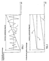
- Fig. 1 the fuel saving amount is shown in the lean operating range over time, wherein the curve 1 shows the time course of the fuel economy during a maximum to be realized lean time.
- Curve 2 represents the integral of the fuel economy during this maximum lean time to be realized.
- Curve 3 represents the averaged time fuel economy during this maximum lean time to be realized.
- this mean fuel saving amount is to be multiplied according to curve 3 with the maximum lean time to be realized.
- the averaged time between two torque requirements that exceed a predefinable load and / or speed limit and that leave the lean operating range can be determined first. This averaged time is related to the evaluation period, i. that different transient torque requests are compared from their time frame and thus the average time value is made available. This averaged time between two torque demands exceeding a predefinable load and / or speed limit value and leaving the lean operating range constitutes a so-called second lean time.
- the first lean time is the quotient of a current nitrogen oxide storage capacity of the nitrogen oxide storage catalytic converter and the averaged nitrogen oxide raw mass flow value .
- the current nitrogen oxide storage capacity of the nitrogen oxide storage catalyst is determined as a function of the temperature and / or the degree of aging and / or the sulfurization.
- the averaged nitrogen oxide raw mass flow value is also determined by the engine control unit for the evaluation period. Then, this first lean time is compared with the second lean time, with the smaller of the two lean times, i. the minimum of these two lean times is taken to be multiplied by the averaged fuel economy in the evaluation period.
- the sum of the lean phases following the lean phase of the required for the discharge of the oxygen storage of the nitrogen oxide storage catalytic converter first fuel amount and a required for the discharge of the nitrogen oxide storage of the nitrogen oxide storage catalyst second fuel quantity is formed.
- This connection is in Fig. 2 shown. From this Fig. 2 it is evident that the amount of fuel for discharge of the oxygen storage is approximately constant (curve 5), while the second amount of fuel for discharging the nitrogen oxide storage (curve 4) is a function of the lean time, since the oxygen storage is already fully loaded immediately after the beginning of a lean operation phase, while the Nitrogen oxides are carriers and therefore need a longer time for addition.
- Curve 6 is the sum of the fuel quantities of the curves 4 and 5. If averaging over time, ie over an evaluation period, then results in a time-related nitrogen oxide storage catalyst loading with nitrogen oxides, so that with a simultaneous consideration of the lean time according to the following formula the fuel excess consumption amount can be calculated:
- Fuel consumption amount (g) oxygen storage amount (g) x first percentage amount of fuel + related to the time-averaged NO x storage amount (g / s) x lean time (s) x second percentage amount of fuel
- the lean time provided here results from the sum of the individual lean operating times in the evaluation period.
- a related to the evaluation period comparison of the fuel under-consumption amount with the fuel consumption more ie a comparison of the curve 2 in Fig. 1 and the curve 6 in FIG Fig. 2 thus enables an operation such that the engine control unit inhibits switching to the lean operating range if the fuel excess consumption amount for the discharges in the evaluation period under consideration, which is preferably about 100 seconds, is equal to or greater than the fuel shortage amount due to the lean operation in FIG this evaluation period. If, on the other hand, the fuel consumption quantity for the discharges is less than the lean fuel consumption amount due to lean operation in this evaluation period, the engine control unit releases a lean operation and thus switching between the lean operation region and the homogeneous operation region.
Landscapes
- Engineering & Computer Science (AREA)
- Chemical & Material Sciences (AREA)
- Combustion & Propulsion (AREA)
- Mechanical Engineering (AREA)
- General Engineering & Computer Science (AREA)
- Electrical Control Of Air Or Fuel Supplied To Internal-Combustion Engine (AREA)
- Exhaust Gas After Treatment (AREA)
Abstract
Claims (7)
- Procédé pour faire fonctionner un moteur à combustion interne d'un véhicule, notamment d'un véhicule automobile, comprenant une première plage de fonctionnement en tant que plage de fonctionnement pauvre, dans laquelle le moteur à combustion interne fonctionne avec un excès d'air et donc avec un mélange pauvre présentant un excès d'oxygène, et dans laquelle les oxydes d'azote produits par le moteur à combustion interne sont accumulés dans un catalyseur à accumulation d'oxydes d'azote, la plage de fonctionnement pauvre étant commutée afin de décharger le catalyseur à accumulation d'oxydes d'azote, au moyen d'un appareil de commande du moteur, à une plage de fonctionnement riche, dans laquelle le moteur à combustion interne fonctionne avec un mélange riche présentant un appauvrissement en air et dans laquelle les oxydes d'azote accumulés dans le catalyseur à accumulation d'oxydes d'azote dans la plage de fonctionnement pauvre sont purgés du catalyseur à accumulation d'oxydes d'azote, et comprenant une deuxième plage de fonctionnement en tant que plage de fonctionnement homogène, dans laquelle le moteur à combustion interne fonctionne avec un mélange sensiblement homogène stoechiométrique (lambda = 1), la commutation entre la plage de fonctionnement pauvre et la plage de fonctionnement homogène étant effectuée par l'appareil de commande du moteur en fonction d'une demande de régime et/ou de charge dépendant du fonctionnement, en présence d'une condition de commutation prédéfinissable, et l'appareil de commande du moteur, avant la commutation de la plage de fonctionnement pauvre à la plage de fonctionnement homogène, commutant d'abord dans une plage de fonctionnement riche pour une décharge du catalyseur à accumulation d'oxydes d'azote, et l'appareil de commande du moteur bloquant la commutation dans la plage de fonctionnement pauvre en fonction d'un critère de blocage prédéfinissable,
caractérisé en ce que
l'appareil de commande du moteur bloque la commutation dans la plage de fonctionnement pauvre si la quantité consommée supplémentaire de carburant pour les décharges dans un intervalle de temps d'analyse prédéfinissable déterminé, s'étendant sur plusieurs phases de fonctionnement pauvre, est supérieure ou égale à la quantité consommée minimale de carburant par le mode de fonctionnement pauvre dans cet intervalle de temps d'analyse,
en ce que l'appareil de commande du moteur autorise un fonctionnement pauvre et donc une commutation entre la plage de fonctionnement pauvre et la plage de fonctionnement homogène, si la quantité consommée supplémentaire de carburant pour les décharges dans l'intervalle de temps d'analyse est inférieure à la quantité consommée minimale de carburant par le mode de fonctionnement pauvre dans cet intervalle de temps d'analyse,
en ce que la quantité consommée minimale de carburant est déterminée en fonction d'une valeur de débit massique brute d'oxydes d'azote moyennée sur l'intervalle de temps d'analyse, en fonction d'une quantité d'économie de carburant moyennée sur l'intervalle de temps d'analyse dans les phases de fonctionnement pauvre se produisant dans l'intervalle de temps d'analyse par rapport aux phases de la plage de fonctionnement homogène dans cet intervalle de temps d'analyse, et en fonction d'une durée moyennée sur l'intervalle de temps d'analyse entre deux demandes de couple dépassant une valeur limite de charge et/ou de régime prédéfinissable et impliquant une sortie de la plage de fonctionnement pauvre, et
en ce que la quantité consommée supplémentaire de carburant est déterminée en fonction d'un état de charge du catalyseur à accumulation moyenné sur l'intervalle de temps d'analyse. - Procédé selon la revendication 1, caractérisé en ce que
la quantité consommée supplémentaire de carburant requise par les phases de fonctionnement riche dans l'intervalle de temps d'analyse se calcule en tant que somme d'une première quantité de carburant nécessaire pour la décharge de l'accumulateur d'oxygène et d'une deuxième quantité de carburant nécessaire pour la décharge de l'accumulateur d'oxydes d'azote,
en ce que la première quantité de carburant par phase de fonctionnement pauvre est approximativement constante, et
en ce que la deuxième quantité de carburant est au moins une fonction de l'émission brute d'oxydes d'azote pendant le fonctionnement pauvre, de telle sorte que la deuxième quantité de carburant soit moyennée sur l'intervalle de temps d'analyse. - Procédé selon la revendication 1 ou la revendication 2, caractérisé en ce que
l'on calcule un premier temps de fonctionnement pauvre à partir du quotient d'une quantité de capacité d'accumulation des oxydes d'azote du catalyseur à accumulation d'oxydes d'azote et de la valeur du débit massique brute d'oxydes d'azote,
en ce que le temps moyenné entre deux demandes de couple dépassant une valeur limite de charge et/ou de régime prédéfinissable et impliquant une sortie de la plage de fonctionnement pauvre, en tant que deuxième temps de fonctionnement pauvre, est comparé avec le premier temps de fonctionnement pauvre, de telle sorte que la plus petite des deux valeurs de temps de fonctionnement pauvre soit ensuite multipliée par la quantité d'économie de carburant moyennée sur l'intervalle de temps d'analyse pour déterminer la quantité consommée minimale de carburant dans l'intervalle de temps d'analyse. - Procédé selon la revendication 3, caractérisé en ce que la quantité actuelle de capacité d'accumulation des oxydes d'azote du catalyseur à accumulation d'oxydes d'azote est déterminée en fonction de la température et/ou du degré de vieillissement et/ou du degré de sulfuration.
- Procédé selon la revendication 3 ou la revendication 4, caractérisé en ce que la valeur actuellement détectée de la capacité d'accumulation des oxydes d'azote du catalyseur à accumulation d'oxydes d'azote est déterminée en fonction du point de fonctionnement en tenant compte du degré de vieillissement et/ou du degré de sulfuration du catalyseur à accumulation d'oxydes d'azote, de telle sorte
que le débit massique d'oxydes d'azote avant le catalyseur à accumulation d'oxydes d'azote et/ou le débit massique d'oxydes d'azote après le catalyseur à accumulation d'oxydes d'azote soient intégrés à chaque fois sur une même durée,
en ce que pour établir l'instant de commutation de la phase d'accumulation à la phase de décharge, et donc de la plage de fonctionnement pauvre à la plage de fonctionnement riche, on détermine, au moins à partir de la valeur intégrale du débit massique d'oxydes d'azote avant et/ou après le catalyseur à accumulation et/ou à partir de l'instant de commutation à chaque fois en satisfaisant une condition de commutation de décharge prédéfinissable dans une première étape, pour déterminer le degré de vieillissement du catalyseur à accumulation, un point de fonctionnement de commutation en fonction d'une température de fonctionnement momentanée à l'instant de commutation, et
en ce que le point de fonctionnement de commutation respectif, dans une deuxième étape pour déterminer le degré de vieillissement du catalyseur à accumulation, est comparé à un champ de capacité du catalyseur à accumulation prédéfinissable, optimisé en termes de consommation de carburant, s'étendant sur une fenêtre de températures, qui est formé par une pluralité de points de fonctionnement pour un catalyseur à accumulation neuf et pour un catalyseur à accumulation vieux, de telle sorte
qu'un point de fonctionnement de commutation se trouvant à l'intérieur du champ de capacité du catalyseur à accumulation ne représente pas un niveau en dessous de la capacité d'accumulation d'oxydes d'azotes minimale, mais représente la variation par rapport au point de fonctionnement antérieur en tant que mesure du vieillissement du catalyseur à accumulation, et
qu'un point de fonctionnement de commutation sortant du champ de capacité du catalyseur à accumulation constitue un niveau inférieur à la capacité d'accumulation d'oxydes d'azotes minimale. - Procédé selon la revendication 5, caractérisé en ce que pour établir l'instant de commutation de la phase d'accumulation dans la phase de décharge, on détermine un glissement d'oxydes d'azote relatif en tant que différence entre le débit massique d'oxydes d'azote affluant dans le catalyseur à accumulation d'oxydes d'azote et le débit massique d'oxydes d'azote sortant du catalyseur à accumulation d'oxydes d'azote, à chaque fois en fonction de la durée d'accumulation, de telle sorte que le quotient des valeurs intégrales du débit massique d'oxydes d'azote avant et après le catalyseur à accumulation d'oxydes d'azote soit mis en outre en relation avec un degré de conversion des oxydes d'azote prédéfinissable, dérivé d'une valeur limite de gaz d'échappement, de sorte qu'en présence de cette condition de commutation prédéfinie, la commutation de la phase d'accumulation à la phase de décharge soit effectuée à l'instant de commutation optimisée en termes de consommation de carburant et de potentiel d'accumulation.
- Procédé selon la revendication 5 ou 6, caractérisé en ce que le champ de capacité du catalyseur à accumulation rapporté à la fenêtre de températures est limité d'une part par une courbe limite pour un nouveau catalyseur à accumulation et d'autre part par une courbe limite pour un catalyseur à accumulation vieilli, représentant un état de vieillissement limite, la fenêtre de températures comprenant des valeurs de températures comprises entre environ 200°C et environ 450°C.
Applications Claiming Priority (3)
| Application Number | Priority Date | Filing Date | Title |
|---|---|---|---|
| DE10253614A DE10253614B4 (de) | 2002-11-15 | 2002-11-15 | Verfahren zum Betreiben einer Brennkraftmaschine eines Fahrzeugs, insbesondere eines Kraftfahrzeuges |
| DE10253614 | 2002-11-15 | ||
| PCT/EP2003/012112 WO2004046529A1 (fr) | 2002-11-15 | 2003-10-31 | Mode de fonctionnement d'un moteur a combustion interne d'un vehicule, notamment d'un vehicule automobile |
Publications (2)
| Publication Number | Publication Date |
|---|---|
| EP1563178A1 EP1563178A1 (fr) | 2005-08-17 |
| EP1563178B1 true EP1563178B1 (fr) | 2010-09-08 |
Family
ID=32240117
Family Applications (1)
| Application Number | Title | Priority Date | Filing Date |
|---|---|---|---|
| EP03775271A Expired - Lifetime EP1563178B1 (fr) | 2002-11-15 | 2003-10-31 | Mode de fonctionnement d'un moteur a combustion interne d'un vehicule, notamment d'un vehicule automobile |
Country Status (5)
| Country | Link |
|---|---|
| US (1) | US7100363B2 (fr) |
| EP (1) | EP1563178B1 (fr) |
| AU (1) | AU2003283332A1 (fr) |
| DE (2) | DE10253614B4 (fr) |
| WO (1) | WO2004046529A1 (fr) |
Families Citing this family (4)
| Publication number | Priority date | Publication date | Assignee | Title |
|---|---|---|---|---|
| DE102004017092B4 (de) * | 2004-04-07 | 2008-10-16 | Audi Ag | Verfahren zur Optimierung des Betriebs eines Otto-Verbrennungsmotors eines Kraftfahrzeugs |
| FR2901317B1 (fr) * | 2006-05-16 | 2008-08-29 | Peugeot Citroen Automobiles Sa | Systeme de commande du declenchement d'une purge de moyens de depollution comportant des moyens formant piege a nox |
| DE112015005082A5 (de) * | 2014-11-10 | 2017-07-27 | Fev Gmbh | Verfahren zum Betreiben einer Verbrennungskraftmaschine mit einem NOx-Speicherkatalysator |
| US12196196B2 (en) | 2021-02-23 | 2025-01-14 | Halliburton Energy Services, Inc. | Pumping unit engine speed oscillation detection and mitigation |
Family Cites Families (9)
| Publication number | Priority date | Publication date | Assignee | Title |
|---|---|---|---|---|
| JP2692530B2 (ja) | 1992-09-02 | 1997-12-17 | トヨタ自動車株式会社 | 内燃機関 |
| JP2900890B2 (ja) * | 1996-08-09 | 1999-06-02 | トヨタ自動車株式会社 | 内燃機関の触媒劣化判別装置 |
| DE19753718C1 (de) * | 1997-12-04 | 1999-07-08 | Daimler Chrysler Ag | Verfahren zum Betreiben eines Dieselmotors |
| JP3858554B2 (ja) * | 2000-02-23 | 2006-12-13 | 株式会社日立製作所 | エンジン排気浄化装置 |
| US6843051B1 (en) * | 2000-03-17 | 2005-01-18 | Ford Global Technologies, Llc | Method and apparatus for controlling lean-burn engine to purge trap of stored NOx |
| JP3958496B2 (ja) * | 2000-05-10 | 2007-08-15 | 三菱電機株式会社 | 内燃機関の排気浄化装置 |
| JP4023115B2 (ja) * | 2001-07-17 | 2007-12-19 | 日産自動車株式会社 | 直噴火花点火式エンジンの制御装置 |
| US6778898B1 (en) * | 2003-02-14 | 2004-08-17 | Ford Global Technologies, Llc | Computer controller for vehicle and engine system with carbon canister vapor storage |
| US6826902B2 (en) * | 2003-03-18 | 2004-12-07 | Ford Global Technologies, Llc | Method and apparatus for estimating oxygen storage capacity and stored NOx in a lean NOx trap (LNT) |
-
2002
- 2002-11-15 DE DE10253614A patent/DE10253614B4/de not_active Expired - Lifetime
-
2003
- 2003-10-31 US US10/534,980 patent/US7100363B2/en not_active Expired - Fee Related
- 2003-10-31 WO PCT/EP2003/012112 patent/WO2004046529A1/fr not_active Ceased
- 2003-10-31 EP EP03775271A patent/EP1563178B1/fr not_active Expired - Lifetime
- 2003-10-31 DE DE50313079T patent/DE50313079D1/de not_active Expired - Lifetime
- 2003-10-31 AU AU2003283332A patent/AU2003283332A1/en not_active Abandoned
Also Published As
| Publication number | Publication date |
|---|---|
| US7100363B2 (en) | 2006-09-05 |
| DE10253614A1 (de) | 2004-06-03 |
| EP1563178A1 (fr) | 2005-08-17 |
| DE50313079D1 (de) | 2010-10-21 |
| WO2004046529A1 (fr) | 2004-06-03 |
| US20060162319A1 (en) | 2006-07-27 |
| DE10253614B4 (de) | 2008-12-24 |
| AU2003283332A1 (en) | 2004-06-15 |
Similar Documents
| Publication | Publication Date | Title |
|---|---|---|
| EP0829623B1 (fr) | Procédé pour éliminer les oxydes d'azote de gaz d'échappement | |
| DE69816939T2 (de) | Vorrichtung zur Abgasreinigung für eine Brennkraftmaschine | |
| EP1161618B1 (fr) | Procede de desulfatage d'un catalyseur accumulateur de nox | |
| EP0930930A1 (fr) | PROCEDE D'EPURATION DE GAZ D'ECHAPPEMENT CONTENANT DU NOx | |
| EP1579109A1 (fr) | Dispositif et procede de post-traitement de gaz d'echappement | |
| EP3584418B1 (fr) | Système de post-traitement des gaz d'échappement et procédé de régénération d'un filtre à particules | |
| DE10126455B4 (de) | Verfahren zur Desulfatisierung eines Stickoxid-Speicherkatalysators | |
| WO1999033548A1 (fr) | REGENERATION D'UN CATALYSEUR A ACCUMULATEUR DE NOx DANS UN MOTEUR A COMBUSTION INTERNE | |
| EP3404228A1 (fr) | Régénération d'un filtre à particules ou catalyseur à quatre voies dans une installation d'échappement d'un moteur à combustion interne | |
| DE102015209979B4 (de) | Verfahren zum Bestimmen eines Hybridantrieb-Drehmomentschwellwertes, zum Betrieb einer Hybridantriebsvorrichtung und Hybridfahrzeug | |
| EP1563178B1 (fr) | Mode de fonctionnement d'un moteur a combustion interne d'un vehicule, notamment d'un vehicule automobile | |
| DE10226873B4 (de) | Verfahren zur Steuerung der Betriebsartenwahl einer Verbrennungskraftmaschine | |
| DE10154041B4 (de) | Verfahren und Vorrichtung zur Reduzierung einer Schadstoffendemission | |
| DE10241497B3 (de) | Verfahren zur Steuerung des Magerbetriebs einer einen Stickoxid-Speicherkatalysator aufweisenden Brennkraftmaschine, insbesondere eines Kraftfahrzeuges | |
| DE102018203859A1 (de) | Verfahren, Verarbeitungs- und Steuereinheit sowie Anordnung zum Regenerieren eines LNT-Katalysators und Kraftfahrzeug | |
| EP1540151B1 (fr) | Procede pour determiner le degre de vieillissement d'un catalyseur accumulateur d'oxyde d'azote d'un moteur a combustion interne, notamment d'une automobile | |
| EP1300572B1 (fr) | Procédé et dispositif de commande d'un moteur pouvant fonctionner avec un mélange pauvre | |
| DE10130053B4 (de) | Verfahren und Vorrichtung zur Entschwefelung eines NOX-Speicherkatalysators | |
| EP1540160B1 (fr) | Procede permettant de faire fonctionner un pot catalytique a accumulation de dioxyde d'azote d'un moteur a combustion interne notamment d'un vehicule automobile | |
| DE10010031B4 (de) | Verfahren und Vorrichtung zur Durchführung einer NOx-Regeneration eines in einem Abgaskanal einer Verbrennungskraftmaschine angeordneten NOx-Speicherkatalysators | |
| DE10164931B4 (de) | Verfahren zur Desulfatisierung eines Stickoxid-Speicherkatalysators und Anwendung des Verfahrens | |
| WO2017153048A1 (fr) | Procédé d'activation pour un revêtement contenant des métaux nobles d'une unité de post-traitement des gaz d'échappement à catalyse par oxydation pouvant être traversée par les gaz d'échappement | |
| DE10260886B4 (de) | Verfahren zur Durchführung einer NOx-Regeneration sowie Mehrzylindermotor mit mehrflutiger Abgasreinigungsanlage | |
| DE10249609B4 (de) | Verfahren zur Steuerung eines NOx-Speicherkatalysators | |
| DE10349854B4 (de) | Verfahren und Vorrichtung zur Entschwefelung eines NOx-Speicherkatalysators |
Legal Events
| Date | Code | Title | Description |
|---|---|---|---|
| PUAI | Public reference made under article 153(3) epc to a published international application that has entered the european phase |
Free format text: ORIGINAL CODE: 0009012 |
|
| 17P | Request for examination filed |
Effective date: 20050615 |
|
| AK | Designated contracting states |
Kind code of ref document: A1 Designated state(s): AT BE BG CH CY CZ DE DK EE ES FI FR GB GR HU IE IT LI LU MC NL PT RO SE SI SK TR |
|
| AX | Request for extension of the european patent |
Extension state: AL LT LV MK |
|
| DAX | Request for extension of the european patent (deleted) | ||
| RBV | Designated contracting states (corrected) |
Designated state(s): DE FR GB |
|
| RIN1 | Information on inventor provided before grant (corrected) |
Inventor name: ODENDALL, BODO |
|
| 17Q | First examination report despatched |
Effective date: 20091103 |
|
| GRAP | Despatch of communication of intention to grant a patent |
Free format text: ORIGINAL CODE: EPIDOSNIGR1 |
|
| GRAS | Grant fee paid |
Free format text: ORIGINAL CODE: EPIDOSNIGR3 |
|
| GRAA | (expected) grant |
Free format text: ORIGINAL CODE: 0009210 |
|
| AK | Designated contracting states |
Kind code of ref document: B1 Designated state(s): DE FR GB |
|
| REG | Reference to a national code |
Ref country code: GB Ref legal event code: FG4D Free format text: NOT ENGLISH |
|
| REF | Corresponds to: |
Ref document number: 50313079 Country of ref document: DE Date of ref document: 20101021 Kind code of ref document: P |
|
| PLBE | No opposition filed within time limit |
Free format text: ORIGINAL CODE: 0009261 |
|
| STAA | Information on the status of an ep patent application or granted ep patent |
Free format text: STATUS: NO OPPOSITION FILED WITHIN TIME LIMIT |
|
| 26N | No opposition filed |
Effective date: 20110609 |
|
| REG | Reference to a national code |
Ref country code: DE Ref legal event code: R097 Ref document number: 50313079 Country of ref document: DE Effective date: 20110609 |
|
| REG | Reference to a national code |
Ref country code: DE Ref legal event code: R084 Ref document number: 50313079 Country of ref document: DE |
|
| REG | Reference to a national code |
Ref country code: DE Ref legal event code: R084 Ref document number: 50313079 Country of ref document: DE Effective date: 20111121 |
|
| PGFP | Annual fee paid to national office [announced via postgrant information from national office to epo] |
Ref country code: DE Payment date: 20141031 Year of fee payment: 12 Ref country code: GB Payment date: 20141022 Year of fee payment: 12 Ref country code: FR Payment date: 20141021 Year of fee payment: 12 |
|
| REG | Reference to a national code |
Ref country code: DE Ref legal event code: R119 Ref document number: 50313079 Country of ref document: DE |
|
| GBPC | Gb: european patent ceased through non-payment of renewal fee |
Effective date: 20151031 |
|
| PG25 | Lapsed in a contracting state [announced via postgrant information from national office to epo] |
Ref country code: DE Free format text: LAPSE BECAUSE OF NON-PAYMENT OF DUE FEES Effective date: 20160503 Ref country code: GB Free format text: LAPSE BECAUSE OF NON-PAYMENT OF DUE FEES Effective date: 20151031 |
|
| REG | Reference to a national code |
Ref country code: FR Ref legal event code: ST Effective date: 20160630 |
|
| PG25 | Lapsed in a contracting state [announced via postgrant information from national office to epo] |
Ref country code: FR Free format text: LAPSE BECAUSE OF NON-PAYMENT OF DUE FEES Effective date: 20151102 |