EP1563634B1 - Dateneinheit-sender und verfahren zu dessen steuerung - Google Patents
Dateneinheit-sender und verfahren zu dessen steuerung Download PDFInfo
- Publication number
- EP1563634B1 EP1563634B1 EP02787722A EP02787722A EP1563634B1 EP 1563634 B1 EP1563634 B1 EP 1563634B1 EP 02787722 A EP02787722 A EP 02787722A EP 02787722 A EP02787722 A EP 02787722A EP 1563634 B1 EP1563634 B1 EP 1563634B1
- Authority
- EP
- European Patent Office
- Prior art keywords
- time
- data unit
- out period
- procedure
- sender
- Prior art date
- Legal status (The legal status is an assumption and is not a legal conclusion. Google has not performed a legal analysis and makes no representation as to the accuracy of the status listed.)
- Expired - Lifetime
Links
- 238000000034 method Methods 0.000 title claims abstract description 129
- 230000005540 biological transmission Effects 0.000 claims abstract description 52
- 238000012544 monitoring process Methods 0.000 claims abstract description 43
- 238000004891 communication Methods 0.000 claims description 27
- 230000004044 response Effects 0.000 claims description 27
- 238000004590 computer program Methods 0.000 claims description 4
- 238000012545 processing Methods 0.000 claims description 3
- 230000006870 function Effects 0.000 description 6
- 230000003111 delayed effect Effects 0.000 description 4
- 230000004048 modification Effects 0.000 description 4
- 238000012986 modification Methods 0.000 description 4
- 230000009467 reduction Effects 0.000 description 4
- 230000007246 mechanism Effects 0.000 description 3
- 230000001960 triggered effect Effects 0.000 description 3
- 238000010586 diagram Methods 0.000 description 2
- 230000003139 buffering effect Effects 0.000 description 1
- 230000001934 delay Effects 0.000 description 1
- 230000001419 dependent effect Effects 0.000 description 1
- 238000001514 detection method Methods 0.000 description 1
- 230000000694 effects Effects 0.000 description 1
- 238000005516 engineering process Methods 0.000 description 1
- 230000002452 interceptive effect Effects 0.000 description 1
- 238000010295 mobile communication Methods 0.000 description 1
- 230000002035 prolonged effect Effects 0.000 description 1
Images




Classifications
-
- H—ELECTRICITY
- H04—ELECTRIC COMMUNICATION TECHNIQUE
- H04L—TRANSMISSION OF DIGITAL INFORMATION, e.g. TELEGRAPHIC COMMUNICATION
- H04L1/00—Arrangements for detecting or preventing errors in the information received
- H04L1/12—Arrangements for detecting or preventing errors in the information received by using return channel
- H04L1/16—Arrangements for detecting or preventing errors in the information received by using return channel in which the return channel carries supervisory signals, e.g. repetition request signals
- H04L1/18—Automatic repetition systems, e.g. Van Duuren systems
- H04L1/1867—Arrangements specially adapted for the transmitter end
- H04L1/188—Time-out mechanisms
-
- H—ELECTRICITY
- H04—ELECTRIC COMMUNICATION TECHNIQUE
- H04L—TRANSMISSION OF DIGITAL INFORMATION, e.g. TELEGRAPHIC COMMUNICATION
- H04L1/00—Arrangements for detecting or preventing errors in the information received
- H04L1/12—Arrangements for detecting or preventing errors in the information received by using return channel
- H04L1/16—Arrangements for detecting or preventing errors in the information received by using return channel in which the return channel carries supervisory signals, e.g. repetition request signals
- H04L1/18—Automatic repetition systems, e.g. Van Duuren systems
- H04L1/1867—Arrangements specially adapted for the transmitter end
- H04L1/1874—Buffer management
Definitions
- the present invention relates to a data unit sender and a method of controlling a data unit sender, said data unit sender being arranged to operate in accordance with a communication protocol that provides for a feedback function according to which the sender receives feedback messages that report on the receipt of data units at the receiver of the data unit communication.
- feedback messages are explicit congestion notifications (ECN) originating in the network carrying the data communication, acknowledgment messages originating at the receiver of the data communication, which acknowledge the correct receipt of a transmitted data unit, or non-acknowledgment messages that inform of the non-receipt of sent data units.
- ECN explicit congestion notifications
- the present invention generally relates to the field of data unit communication.
- Data unit communication means that an amount of data to be transmitted is divided into individual units, which are then sent over a communication path, e.g. via a network, to a receiver.
- data units carry different names, depending on the specific context and the technology e.g. packet, segment, frame, protocol data unit, etc., and the term "data unit" is used generically in the present application to encompass all such sub-divisions of a data amount.
- the concept of data unit oriented communication is usually accompanied by the concept of protocol layering.
- data units being sent will adhere to the requirements of a given communication protocol (e.g. the Transmission Control Protocol TCP), and the given protocol will be part of a stack of protocols.
- the data unit sender and data unit receiver in a given communication of data units of a given protocol are also referred to as peers for said protocol and said communication.
- a data unit sender for sending data unit of a given protocol will generally receive data from a higher layer and then place this received data into data units adhering to the protocol(s) of the given layer.
- a data unit sender will therefore have a buffer for storing data to be sent.
- the concept of communication protocols and protocol layering is well known in the art and does not need to be explained in more detail here.
- data unit senders will simply take all data in its send buffer, prepare appropriate data units and send these data units as quickly as possible
- data unit senders usually implement a flow control procedure for controlling the flow of data sent by the data unit sender, where said flow control procedure is arranged such that at any given moment the amount of previously unsent data that the sender can send at once is limited by an available transmission capacity value.
- the reason for this is that the data unit sender will typically not have an infinite amount of bandwidth available for its communication with a data unit receiver. Therefore, it is necessary to implement some sort of restriction on the amount of data that the data unit sender can send at once.
- window based flow control in which the data unit sender maintains a control parameter referred to as the send window, and the data unit sender is not allowed to have more data units outstanding than indicated by the send window.
- the send window is measured in an amount of data, e.g. bits or bytes.
- a data unit is referred to as "outstanding” if it has been sent, but the data unit sender has not yet received a feedback message that confirms the correct receipt of said data unit at the data unit receiver.
- the amount of data that the sender can send at once is limited to the difference between the send window size and the amount of data in outstanding data units. It is that limit that we refer to as above mentioned "available transmission capacity value”.
- the data unit sender can maintain a plurality of windows, e.g. such as the congestion window and advertised window known from TCP, where the send window is selected among that plurality, e.g. as the smallest of said.plurality.
- windows e.g. such as the congestion window and advertised window known from TCP
- the send window is selected among that plurality, e.g. as the smallest of said.plurality.
- the concept of window based flow control is well known in the art and does not need to be described in more detail here.
- rate based flow control Another example of a flow control procedure in which the amount of previously unsent data that the sender can send at once is limited by an available transmission capacity value, is rate based flow control.
- rate based flow control is the so-called TCP Friendly Rate Control (TFRC) protocol, as described in an Internet draft available from the Internet Engineering Task Force (IETF) at www.ietf.org, e.g. the draft of October 22, 2002 available under http://www.ietf.org/Internet-drafts/draft/ietf-tsvwg-tfrc-05.txt.
- TFRC TCP Friendly Rate Control
- the data unit sender calculates a transmit rate according to a predetermined throughput equation, such that the amount of data that the sender can send at once is limited by the transmit rate momentarily allowed by the throughput equation.
- a time-out function is arranged such that the data unit sender monitors a time-out period, and if no feedback message for a designated data unit arrives before the time-out period has expired, the designated data unit is retransmitted, as it is assumed that it was lost.
- Such a time-out concept is employed in many protocols, e. g. in the form of the Retransmission Time-Out (RTO) function in TCP.
- RTO Retransmission Time-Out
- a round-trip communications delay between two devices that communicate with one another over a communications network is repeatedly measured. Based upon at least one of the round-trip communications delays, an adjustable retransmission time-out is adjusted. A message that is not acknowledged during the retransmission time-out is retransmitted.
- the object of the invention is to provide an improved method of controlling a data unit sender, and an improved data unit sender.
- the time-out monitoring procedure uses a first time-out period and a second time-out period, where the second time-out period is shorter than the first time-out period. Then, if upon the expiration of the second (shorter) time-out period the available transmission capacity value for unsent data is greater or equal to the size of the designated data unit that is to be retransmitted, then the designated data unit is retransmitted.
- the present invention proposes to implement a short time-out period and a long time-out period, where a retransmission occurs after expiration of the short time-out period if the fair share of load on the part of the data unit sender is not exceeded, i.e., if permitted by the above mentioned "available transmission capacity value".
- available transmission capacity value if the sender is not fully utilizing its transmission capacity for sending yet unsent data, it should be allowed to use this available capacity in any desired way, especially to also retransmit a designated data unit. Thereby, a faster or more aggressive time-out function can be implemented without overloading the network into which the data units are sent.
- a data unit sender is not fully using its available transmission capacity. For example, this can be due to the fact that the data unit sender is not receiving more data from a higher layer, e.g. from an application that generates data for the data unit sender to transmit. This can e.g. be the case in interactive applications, such as Telnet, chat, or WWW-interactions, in which the data unit sender (when using the Internet, the data unit sender can be a TCP sender) only has very few data units outstanding (outstanding data units are sometimes also referred to as data units "in flight") at any given time, because the sending application does not have more data to send.
- interactive applications such as Telnet, chat, or WWW-interactions
- the data unit sender can then implement a more aggressive time-out feature and retransmit potentially lost data units more quickly. This increases the data throughput, without overloading the transmission network, as the transmission capacity available to the data unit sender is sufficient for the retransmission.
- the time-out mechanism employs the longer (first) time-out period, and retransmits the designated data unit if no feedback message is received within the longer time-out period, regardless of the available transmission capacity, as is known conventionally, e.g. from the RTO mechanism of TCP.
- the concept of the present invention is applied to a TCP sender, and the first (longer) time-out period is the conventional RTO value.
- one of the basic aspects of the present invention is to allow the data unit sender to employ a more aggressive time-out period if the available transmission capacity allows this. It is not important why there is any transmission capacity available, e.g. in a window based flow control system, why the send window is not being fully utilized. This can be due to the fact that there is no or only little data to be sent in the send buffer, or there can be other reasons for holding back data in the send buffer, e.g. that the data unit sender is waiting for the data received from a higher layer to be placed into a desired order.
- the designated data unit is only retransmitted upon expiration of the second (shorter) time-out period if the amount of unsent data in the send buffer is smaller or equal to a predetermined threshold value.
- the sending of data in the send buffer is accorded priority over the more aggressive retransmission of data units, such that if there is more than a predetermined threshold of yet unsent data in the send buffer, no retransmission is conducted upon expiration of the shorter time-out period, in order to leave the available transmission capacity for the (potential) sending of yet unsent data.
- Fig. 1 shows a flow chart of a first embodiment of the present invention.
- the processing of Fig. 1 starts upon the occurrence of a predetermined event that triggers a time-out monitoring procedure.
- a time-out monitoring procedure triggering event can be chosen in any suitable or desirable way.
- it can be the first sending of a data unit (i.e. the data unit has as of yet not been sent), which is also referred to as the initial transmission of a data unit.
- the ensuing time-out monitoring procedure can relate to the question of whether to retransmit said data unit or not.
- a time-out monitoring procedure can also be triggered by other events, e.g.
- the designated data unit for which it is determined whether a feedback message arrives within the time-out period can be the oldest data unit for which no feedback message has yet been received, e.g. for the oldest unacknowledged data unit if acknowledgments for the correct receipt are used as feedback messages.
- the triggering event can be the receipt of an acknowledgment.
- the designated data unit can again be the oldest outstanding or unacknowledged data unit.
- step S1 a short time-out period is set in an appropriate timer.
- This timer will also be referred to as a retransmission timer REXMT, and the shorter time-out period will also be referred to as the quick retransmission timeout value QRTO. Therefore, step S1 consists in setting REXMT to the value of QRTO. Furthermore, REXMT is set to start counting down the value.
- a time-out monitoring sub-procedure consisting of steps S2 and S3
- an acknowledgment of the designated data unit e.g. the data unit of which the initial transmission triggered the time-out monitoring, or the oldest outstanding data unit, or any other suitable selected data unit
- step S3 it is determined whether the timer REXMT has expired or not.
- acknowledgment messages are used as an example of feedback messages.
- the invention is by no means restricted to acknowledgments (i.e. messages that indicate whether a data unit was correctly received or not), but feedback messages could also be non-acknowledgment messages (i.e. messages that specifically indicate that a given data unit was not received) or some other form of information that lets the data unit sender know if and how a sent data unit was received.
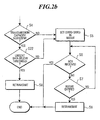
- step S2 if an acknowledgment, that acknowledges the oldest outstanding segment, is received in step S2, then the triggered procedure ends, because no time-out occurred. If no such acknowledgment is received, it is determined whether REXMT has expired in step S3, and if this is not the case, the procedure loops back to step S2, to continue until either an acknowledgment is received or the timer expires. If the timer REXMT expires, then the procedure passes from step S3 to step S4. In step S4, it is determined whether the available transmission capacity value determined in accordance with the implemented flow control procedure is sufficient for re-transmitting the designated data unit.
- step S4 determines that the transmission capacity is not sufficient, e.g. the transmission capacity value allowed for the data sender would be exceeded if the designated data unit were retransmitted, then the procedure goes to step S5, in which the retransmission timer REXMT is reset and restarted with a value (SRTO-QRTO), SRTO being a larger time-out period than QRTO.
- step S5 the time-out monitoring procedure is continued with steps S6 and S7, in which it is determined whether an acknowledgment is received for the designated data unit (step S6) and whether the retransmission timer REXMT has expired or not (step S7). This is basically the same procedure as already explained in connection with steps S2 and S3. If an acknowledgment is received, the time-out monitoring procedure ends, as no time-out has occurred. Otherwise, if no acknowledgment is received within the time-out period, a retransmission is performed in step S9, and the procedure ends thereafter.
- SRTO time-out period
- the value of SRTO is selected as equal to the standard value for the single time-out period defined for that given data unit sender. For example, if the data unit sender is TCP sender, then SRTO may be selected as equal to the standard retransmission time-out value RTO defined in TCP.
- SRTO as the standard time-out period of the data sender to which the invention is applied, this means that if the outcome of step S4 is negative, i.e. no retransmission is conducted upon expiration of QRTO, then the data unit sender simply continues monitoring the time-out period like in the conventional case, i.e. until SRTO expires.
- the data unit sender can conduct a number of procedures as shown in Fig. 1 simultaneously, i.e., it can monitor the time-out for a plurality of designated data units in parallel. Naturally, it is also possible that the data unit sender only monitors one time-out at a time.
- Fig. 1 is a basic embodiment, it may be varied in very many ways. For example, the order of the steps may be changed, and the steps can also be implemented in a different way. For example, it is not necessary to set a value in step 1 and count it down, as it is equally possible to initialise a timer in step S1, let the timer count upwards and then determine in steps S3 and S7 whether the timer has reached predetermined values. It is also possible to use a timer that outputs an absolute time value, and in this case no step S1 is necessary, and in steps S3 and S7 it is determined whether predetermined absolute time values have been reached by the timer.
- the value of SRTO is preferably chosen to correspond to a standard time-out period.
- the second time-out period QRTO is shorter than SRTO.
- QRTO can be chosen to have any desirable value smaller than SRTO.
- the value of QRTO is chosen to be larger than or equal to a predetermined fraction, more preferably one half of the larger time-out value SRTO.
- QRTO be determined on the basis of one or more measured feedback response time values.
- a feedback response time value is a value indicative of the time that passes between the sending of a data unit and the receipt of a feedback message for said sent data unit.
- RTT round trip time
- the data unit sender can be arranged to continuously measure samples of the feedback response time. It may be noted that it is preferably that the longer time-out period SRTO is also determined in dependence on one or more measured feedback response times. For example, in TCP the standard time-out value RTO is determined on the basis of measured round trip times RTT.
- QRTO can e.g. be chosen to be equal to the last measured feedback response time, or equal to the maximum of the last measured feedback response time and SRTO/2. More preferably, QRTO is determined as the maximum of the last measured feedback response time, SRTO/2 and a smoothed average value of the feedback response time.
- An example of such a smoothed average is the parameter smoothed round trip time SRTT defined in the context of TCP.
- QRTO the maximum of the last k measured feedback response times, where k is a natural number.
- QRTO can be chosen as is suitable or appropriate for the given application.
- Fig. 2a shows a variation of the embodiment of Fig. 1 .
- the method described by Fig. 2a contains an additional step S20, where said step S20 precedes steps S1 shown in Fig. 1 . All the steps after step S1 are the same as in Fig. 1 . Consequently, Fig. 2a does not show the further processing.
- Step S20 is performed after the detection of a time-out monitoring procedure triggering event, and determines whether the amount of unsent data in the send buffer is smaller than or equal to a predetermined threshold value. If this is not the case, e.g.
- step S21 in which a standard time-out monitoring procedure is conducted, using the larger time-out period SRTO, preferably a standard time-out period.
- SRTO time-out period
- the inventive procedure explained in connection with Fig. 1 is conducted, i.e. the procedure goes to step S1.
- the control procedure using the shorter, more aggressive value QRTO is only entered if initially the amount of unsent data in the send buffer is not beyond a given limit or threshold. This means that the possibility of using a shorter time-out period is not provided if there is more than a certain amount of yet unsent data to be transmitted. In other words, this embodiment gives priority to the sending of unsent data over the possibility of achieving a faster retransmission of a possibly lost data unit.
- the threshold value used in step S20 can be chosen in any suitable or desirable way. For example, it can be set to zero, which means that the possibility of quicker retransmission is only enabled if at the time of triggering the time-out period the send buffer for previously unsent data is empty, i.e. there is no yet unsent data to be sent.
- a larger value can also be chosen for the threshold, e.g. one or a predetermined multiple of a maximum data unit size defined by the flow control procedure. For example, in the context of TCP, such a maximum data unit size is also referred to as maximum segment size MSS.
- Fig. 2b shows a further variation of the embodiment of Fig. 1 , where the embodiment of Fig. 2b may or may not be combined with Fig. 2a .
- an additional step S22 is provided, which in itself is identical to the step S20 discussed in connection with Fig. 2a . Namely, after step S4 determines that the transmission capacity is sufficient for allowing a retransmission of the designated data unit, step S22 determines whether the amount of unsent data in the send buffer is below a predetermined threshold. If this is not the case, then the quick retransmit of step S8 is not performed, much rather the procedure goes to step S5, step S5 and the subsequent steps S6, S7 and S9 already having been explained in connection with Fig. 1 , such that no repetition is necessary.
- steps S20 and S22 can also implemented together, but using respectively different threshold values.
- step S22 discussed in connection with Fig. 2b
- step S20 discussed in connection with Fig. 2a
- QRTO The quick retransmission in accordance with the shorter time-out period QRTO is only conducted if the amount of unsent data is not too great, i.e. not above a predetermined threshold.
- the time-out monitoring procedure conducted in the data unit sender is furthermore arranged to perform a congestion control procedure subsequent to the expiration of the shorter time-out period QRTO.
- the congestion control procedure comprises an adjustment procedure for adjusting one or more parameters used in the flow control procedure, such that the amount of previously unsent data that the sender is allowed to send at once is reduced.
- the adjustment procedure can consist in reducing the send window, and in the case of rate base flow control reducing the allowed transmit rate. The purpose of such measures is to reduce the load on the network transporting the sent data units.
- TCP Transmission Control Protocol
- congestion window cwnd the so-called congestion window
- slow start threshold ssthresh the so-called slow start threshold
- Fig. 3 shows an example in which congestion control is implemented in addition to the basic time-out monitoring steps discussed in Figs. 1 , 2a and 2b .
- Fig. 3 The procedure shown in Fig. 3 can be combined with that shown in Fig. 1 or Fig. 2b , and would be performed subsequent to step S4 (in the example of Fig. 1 ) or step S22 (in the example of Fig. 2b ), which is indicated schematically at the top of Fig. 3 .
- Step S5 known from Figs. 1 and 2b is also indicated in Fig. 3 , but the steps subsequent thereto (S6, S9) are no longer shown for simplicity.
- step S30 in which it is determined whether delayed congestion control should be performed or not. If no delayed congestion control is performed, then upon expiration of the short time-out period QRTO the designated data unit is retransmitted in step S8 and an adjustment of flow control parameters is conducted in step S31. It may be noted that it is not necessary to implement step S30, and if it is desired to always combine the retransmission of step S8 with an adjustment of one or more flow control parameters as a part of a congestion control procedure, step S31 could also simply be added to the flow charts of Figs. 1 or 2b , immediately before or immediately after step S8.
- step S30 is implemented as an option for operating the data unit sender.
- the data unit sender when the data unit sender is configured, it can be configured to perform a delayed congestion control or not. If the delayed congestion control is configured, such that the result of step S30 is "yes", then the procedure passes to step S32, in which a retransmission is conducted and then the retransmission timer REXMT is set to (SRTO-QRTO). Then, an intermediate monitoring procedure during the intermediate.period (SRTO-QRTO) is conducted, in order to determine whether a feedback message (e.g. an acknowledgment) is received within said intermediate period SRTO-QRTO.
- a feedback message e.g. an acknowledgment
- step S35 i.e. the first type of adjustment
- no acknowledgment has been received within the long time-out period SRTO.
- the type one adjustment of flow control parameters in step S35 is arranged such that it appropriately responds to the loss of a data unit.
- step S36 if the procedure passes to step S36, this means that although no acknowledgment was received within the short time-out period QRTO, an acknowledgment was received within the longer time-out period SRTO. As a consequence, it is well possible that the designated data unit was not lost. It may be remarked that if the acknowledgment received in step S32 was for the retransmission performed in step S32, then this is an indication that the original transmission was lost, whereas if the acknowledgment received in step S33 relates to the original transmission, it is clear that this original transmission was definitely not lost. However, the example of Fig. 3 does not distinguish between which transmission (i.e.
- the acknowledgment message relates to, such that the conclusion from having arrived at step S36 is that the probability of the designated data unit not having been lost is in any case larger than that probability when having arrived at step S35. Consequently, the second type adjustment of flow control parameters performed in step S36 takes this conclusion into account, and will be arranged in such a way that the flow control procedure is not limited as strongly with respect to the amount of data it can send at once, as for the type adjustment performed in step S35.
- the type one adjustment performed in step S35 could consist in reducing the congestion window to the predetermined size designed to combat data loss, said predetermined size being referred to as the loss window in the present application.
- the loss window is typically one MSS, but could be in principle also be a different value.
- step S35 in the context of TCP could provide that the slow start threshold ssthresh is reduced to one half the value of the congestion window prior to the reduction of the loss window.
- the type two adjustment of step S36 could consist in again setting the slow start threshold ssthresh to one half the congestion windows size, but to only reduce the congestion window to one half its size, as opposed to the stronger reduction in step S35.
- the parameters can also be changed in a different fashion, as is suitable or desirable.
- step S36 will influence the flow control procedure in such a way that the subsequent reduction in allowed transmission capacity for reducing the load on the communication network will be lesser than the reduction in allowed transmission capacity caused by the adjustment of type 1 in step S35. This can go so far as to not performing any changes to the flow control parameters in step S36.
- step S35 could e.g. comprise restarting REXMT with (SRTO+QRTO), while the adjustment procedure in step S31 could e.g. comprise restarting REXMT with 2xSRTO.
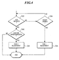
- Fig. 4 shows a preferred variation of the embodiment of Fig. 3 , in that an additional step S40 is provided subsequent to step S33.
- the remaining steps are identical to those shown in Fig. 3 , such that a renewed description is not necessary.
- the data unit sender is arranged to be able to distinguish whether a received feedback message relates to the retransmission of the designated data unit performed in step S32, or to a prior transmission of the designated data unit.
- step S40 is arranged to distinguish whether the feedback message (e.g. acknowledgment) relates to the retransmission sent in S32, or not.
- the feedback message e.g. acknowledgment
- step S33 If the acknowledgment received in step S33 does not relate to the retransmission of step S32, then the overall adjustment procedure is such that the flow control parameters are left unchanged, as the result of step S40 indicates that the designated data unit was in fact not lost. As it was not lost, there is no necessity to perform any congestion control measures, because there is in fact no indication of strong congestion in the network. Although not shown, it is however also conceivable to provide an arbitrary third type adjustment of flow control parameters in response to determining that the acknowledgment received in step S33 does not relate to the retransmission of step S32.
- the capability of the data unit sender or the intermediate monitoring procedure to distinguish between feedback messages relating to the retransmission or a prior transmission can be implemented in any suitable or desirable way. For example, this can be accomplished with the help of a time-stamp function, according to which the data unit sender includes a time-stamp in each sent data unit, and the receiver includes the same time-stamp in feedback messages, such that the data unit sender can unambiguously identify to which transmission a feedback message relates.
- Another possibility of distinguishing between different transmissions is to include a specific initial transmission/retransmission identifier in sent data units, which can be as simple as a single bit that differentiates between an initial transmission and a retransmission.
- Fig. 5 shows a schematic block diagram of a data unit sender arranged in accordance with the present invention.
- Fig. 5 shows a send buffer 51 and a control unit 52.
- the send buffer 51 can be any type of memory suitable for buffering data
- the control unit 52 can be a microprocessor.
- the data unit sender is represented in Fig. 5 as a peer in a communication at a protocol layer n, where the communication with the receiving peer is symbolized by double-arrow 53.
- the buffer 51 receives data from a higher layer n+1 and prepares data units that adhere to the protocol according to which the data unit sender is implemented, under the control of control unit 52, and passes these data units to a lower layer n-1.
- the control unit 52 is schematically indicated as comprising a flow controller 521 for controlling the flow of data sent by the data unit sender, a detector 522 for detecting a time-out monitoring procedure triggering event, and a time-out monitor 523 for determining whether a time-out has occurred within a short time-out period QRTO or within a longer time-out period SRTO, in accordance with the methods described in connection with Figs. 1 to 4 .
- the control unit 52 is arranged to implement the various method embodiments described above.
- the data unit sender of the present invention can be implemented in the form of hardware, software or any suitable combination of hardware and software. Therefore, the present invention can also be embodied as a computer program that is arranged to execute one of the methods described in connection with Figures 1 to 4 when loaded into and executed by a device that is connectable to a communication network and can act as a data unit sender, such as a personal computer suitably connected to the Internet or a mobile communication device arranged for data unit communication, and the present invention can be embodied by a data carrier carrying such a computer program.
Landscapes
- Engineering & Computer Science (AREA)
- Computer Networks & Wireless Communication (AREA)
- Signal Processing (AREA)
- Communication Control (AREA)
- Data Exchanges In Wide-Area Networks (AREA)
- Detection And Prevention Of Errors In Transmission (AREA)
- Radar Systems Or Details Thereof (AREA)
Claims (26)
- Ein Verfahren zum Steuern eines Dateneinheitssenders, der ausgelegt ist, in Übereinstimmung mit einem Kommunikationsprotokoll, das eine Rückmeldungsfunktion vorsieht, gemäß der ein Sender in einer Dateneinheitskommunikation den Empfang von Dateneinheiten meldenden Rückmeldungsnachrichten von einem Empfänger empfängt, zu funktionieren, und wobei der Dateneinheitssender einen Sende-Puffer (51) zum Speichern von zu sendenden Daten aufweist, wobei das Verfahren umfasst:einen Fluss-Steuerungsablauf zum Steuern des Flusses von vom Dateneinheitssender gesendeten Daten, wobei der Fluss-Steuerungsablauf so ausgelegt ist, dass stets die Menge von bislang ungesendeten Daten, die der Sender auf einmal senden kann, durch einen Wert der verfügbaren Übertragungskapazität begrenzt wird,einen Ablauf zum Erfassen eines Time-out-Überwachungsablaufs-Auslöseereignisses,einen Time-out-Überwachungsablauf zum Überwachen, ob eine Rückmeldungsnachricht für eine designierte Dateneinheit vor Ablauf einer vorbestimmten Time-out-Zeitdauer ankommt, wobei die vorbestimmte Time-out-Zeitdauer beim Eintritt des Time-out-Überwachungsablaufs-Auslöseereignisses beginnt, und zum erneuten Übertragen der designierten Dateneinheit, wenn die vorbestimmte Time-out-Zeitdauer abläuft, ohne dass die Bestätigungsnachricht angekommen ist,wobei
die vorbestimmte Time-out-Zeitdauer eine erste Time-out-Zeitdauer darstellt, und
der Time-out-Überwachungsablauf ausgelegt ist, eine erneute Übertragung der designierten Dateneinheit nach Ablauf einer zweiten Time-out-Zeitdauer, die beim Eintritt des Time-out-Überwachungsablaufs-Auslöseereignisses beginnt und kürzer ist als die erste Time-out-Zeitdauer, durchzuführen, wenn nach dem Ablauf der zweiten Time-out-Zeitdauer der Wert der verfügbaren Übertragungskapazität für ungesendete Daten größer oder gleich der Größe der designierten Dateneinheit ist. - Ein Verfahren nach Patentanspruch 1, wobei die designierte Dateneinheit nach Ablauf der zweiten Time-out-Zeitdauer nur dann erneut übertragen wird, wenn die Menge von ungesendeten Daten im Sende-Puffer (51) kleiner oder gleich einem Schwellwert ist.
- Ein Verfahren nach einem der vorangehenden Patentansprüche, wobei der Time-out-Überwachungsablauf weiterhin ausgelegt ist, einen Überlast-Steuerungsablauf im Anschluss an den Ablauf der zweiten Time-out-Zeitdauer durchzuführen, wobei der Überlast-Steuerungsablauf einen Regulierungsablauf zum Regulieren von einem oder mehreren Parameter(n), der/die vom Fluss-Steuerungsablauf verwendet wird/werden, so dass die Menge von bislang ungesendeten Daten, die dem Sender gewährt wird, auf einmal zu senden, eingeschränkt wird.
- Ein Verfahren nach Patentanspruch 3, wobei der Überlast-Steuerungsablauf ausgelegt ist, den Regulierungsablauf nach Ablauf der zweiten Time-out-Zeitdauer durchzuführen.
- Ein Verfahren nach Patentanspruch 3, wobei der Überlast-Steuerungsablauf ausgelegt ist, die Durchführung des Regulierungsablaufs zu verzögern und einen dazwischen liegenden Überwachungsablauf während einer dazwischen liegenden Zeitdauer zwischen dem Ablauf der zweiten Time-out-Zeitdauer und der ersten Time-out-Zeitdauer durchzuführen, wobei der dazwischen liegende Überwachungsablauf ausgelegt ist, zu erfassen, ob eine die designierte Dateneinheit betreffende Rückmeldungsnachricht innerhalb der dazwischen liegenden Zeitdauer ankommt, und wobei der Regulierungsablauf ausgelegt ist, auf das Ergebnis des dazwischen liegenden Überwachungsablaufs zu antworten, um eine erste Regulierung des einen Parameters oder der mehreren Parameter durchzuführen, wenn keine die designierte Dateneinheit betreffende Rückmeldungsnachricht innerhalb der dazwischen liegenden Zeitdauer ankommt, und um eine zweite Regulierung des einen Parameters oder der mehreren Parameter durchzuführen, wenn eine die designierte Dateneinheit betreffende Rückmeldungsnachricht innerhalb der dazwischen liegenden Zeitdauer ankommt, wobei die erste Regulierung sich von der zweiten Regulierung unterscheidet.
- Ein Verfahren nach Patentanspruch 5, wobei der dazwischen liegende Überwachungsablauf ausgelegt ist, fähig zu sein, zu unterscheiden, ob eine empfangene, die designierte Dateneinheit betreffende Rückmeldungsnachricht die erneute Übertragung der designierten Dateneinheit, die nach Ablauf der zweiten Time-out-Zeitdauer durchgeführt wird, betrifft, oder eine vorherige Übertragung der designierten Dateneinheit betrifft, und wobei der Regulierungsablauf ausgelegt ist, den einen oder die mehreren Parameter unverändert zu lassen, wenn die empfangene Rückmeldungsnachricht eine vorherige Übertragung der designierten Dateneinheit betrifft.
- Ein Verfahren nach einem der Patentansprüche 1 bis 6,
wobei der Fluss-Steuerungsablauf fensterbasiert und ausgelegt ist, den Wert der verfügbaren Übertragungskapazität auf der Grundlage der Differenz zwischen einem Sende-Fenster und einer Menge von ausstehenden Daten zu bestimmen. - Ein Verfahren nach einem der Patentansprüche 1 bis 6,
wobei der Fluss-Steuerungsablauf ratenbasiert und ausgelegt ist, den Wert der verfügbaren Übertragungskapazität auf der Grundlage einer zulässigen Übertragungsrate zu bestimmen. - Ein Verfahren nach einem der vorangehenden Patentansprüche, das einen Ablauf zum Messen einer Rückmeldungs-Antwortzeit umfasst, wobei die Rückmeldungs-Antwortzeit die Zeit bezeichnet, die zwischen dem Senden einer Dateneinheit und dem Empfang einer die Dateneinheit betreffende Rückmeldungsnachricht vergeht, wobei die zweite Time-out-Zeitdauer in Abhängigkeit von einem oder mehreren, gemessenen Rückmeldungs-Antwortzeitwert(en) bestimmt wird.
- Ein Verfahren nach Patentanspruch 9, wobei die erste Time-out-Zeitdauer auch in Abhängigkeit von einem oder mehreren, gemessenen Rückmeldungs-Antwortzeitwert(en) bestimmt wird.
- Ein Verfahren nach einem der vorangehenden Patentansprüche, wobei die zweite Time-out-Zeitdauer größer oder gleich einem Bruchteil der ersten Time-out-Zeitdauer ist.
- Ein Verfahren nach einem der vorangehenden Patentansprüche, wobei der Dateneinheitssender ausgelegt ist, in Übereinstimmung mit dem Übertragungs-Steuerungsprotokoll TCP zu funktionieren, und die erste Time-out-Zeitdauer den Standard-TCP-Wiederübertragungs-Time-out-Parameter RTO darstellt.
- Ein Dateneinheitssender, der ausgelegt ist, in Übereinstimmung mit einem Kommunikationsprotokoll, das eine Rückmeldungsfunktion vorsieht, gemäß der ein Sender in einer Dateneinheitskommunikation den Empfang von Dateneinheiten meldenden Rückmeldungsnachrichten empfängt, zu funktionieren, umfassend:einen Sende-Puffer (51) zum Speichern von zu sendenden Dateneinheiten,einen Fluss-Controller (521) zum Steuern des Flusses von vom Dateneinheitssender gesendeten Daten, wobei der Fluss-Controller (521) einen Fluss-Steuerungsablauf durchführt, der so ausgelegt ist, dass stets die Menge von bislang ungesendeten Daten, die der Sender auf einmal senden kann, durch einen Wert der verfügbaren Übertragungskapazität begrenzt wird,einen Erfasser (522) zum Erfassen eines Time-out-Überwachungsablaufs-Auslöseereignisses,einen Time-out-Bildschirm (523) zum Überwachen, ob eine Rückmeldungsnachricht für eine designierte Dateneinheit vor Ablauf einer vorbestimmten Time-out-Zeitdauer ankommt, wobei die vorbestimmte Time-out-Zeitdauer beim Eintritt des Time-out-Überwachungsablaufs-Auslöseereignisses beginnt, und zum erneuten Übertragen der designierten Dateneinheit, wenn die vorbestimmte Time-out-Zeitdauer abläuft, ohne dass die Bestätigungsnachricht angekommen ist, wobei die vorbestimmte Time-out-Zeitdauer eine erste Time-out-Zeitdauer darstellt, undder Time-out-Bildschirm (523) ausgelegt ist, eine erneute Übertragung der designierten Dateneinheit nach Ablauf einer zweiten Time-out-Zeitdauer, die beim Eintritt des Time-out-Überwachungsablaufs-Auslöseereignisses beginnt und kürzer ist als die erste Time-out-Zeitdauer, durchzuführen, wenn nach dem Ablauf der zweiten Time-out-Zeitdauer der Wert der verfügbaren Übertragungskapazität für ungesendete Daten größer oder gleich der Größe der designierten Dateneinheit ist.
- Ein Dateneinheitssender nach Patentanspruch 13, wobei der Time-out-Bildschirm so ausgelegt ist, dass die designierte Dateneinheit nach Ablauf der zweiten Time-out-Zeitdauer nur dann erneut übertragen wird, wenn die Menge von ungesendeten Daten im Sende-Puffer (51) kleiner oder gleich einem Schwellwert ist.
- Ein Dateneinheitssender nach Patentanspruch 13 oder 14,
wobei der Time-out-Bildschirm (523) weiterhin ausgelegt ist, einen Überlast-Steuerungsablauf im Anschluss an den Ablauf der zweiten Time-out-Zeitdauer durchzuführen,
wobei der Überlast-Steuerungsablauf einen Regulierungsablauf zum Regulieren von einem oder mehreren Parameter(n), der/die vom Fluss-Steuerungsablauf verwendet wird/werden, umfasst, so dass die Menge von bislang ungesendeten Daten, die dem Sender gewährt wird, auf einmal zu senden, eingeschränkt wird. - Ein Dateneinheitssender nach Patentanspruch 15, wobei der Überlast-Steuerungsablauf ausgelegt ist, den Regulierungsablauf nach Ablauf der zweiten Time-out-Zeitdauer durchzuführen.
- Ein Dateneinheitssender nach Patentanspruch 15, wobei der Überlast-Steuerungsablauf ausgelegt ist, die Durchführung des Regulierungsablaufs zu verzögern und einen dazwischen liegenden Überwachungsablauf während einer dazwischen liegenden Zeitdauer zwischen dem Ablauf der zweiten Time-out-Zeitdauer und der ersten Time-out-Zeitdauer durchzuführen, wobei der dazwischen liegende Überwachungsablauf ausgelegt ist, zu erfassen, ob eine die designierte Dateneinheit betreffende Rückmeldungsnachricht innerhalb der dazwischen liegenden Zeitdauer ankommt, und wobei der Regulierungsablauf ausgelegt ist, auf das Ergebnis des dazwischen liegenden Überwachungsablaufs zu antworten, um eine erste Regulierung des einen Parameters oder der mehreren Parameter durchzuführen, wenn keine die designierte Dateneinheit betreffende Rückmeldungsnachricht innerhalb der dazwischen liegenden Zeitdauer ankommt, und um eine zweite Regulierung des einen Parameters oder der mehreren Parameter durchzuführen, wenn eine die designierte Dateneinheit betreffende Rückmeldungsnachricht innerhalb der dazwischen liegenden Zeitdauer ankommt, wobei die erste Regulierung sich von der zweiten Regulierung unterscheidet.
- Ein Dateneinheitssender nach Patentanspruch 17, wobei der dazwischen liegende Überwachungsablauf ausgelegt ist, fähig zu sein, zu unterscheiden, ob eine empfangene, die designierte Dateneinheit betreffende Rückmeldungsnachricht die erneute Übertragung der designierten Dateneinheit, die nach Ablauf der zweiten Time-out-Zeitdauer durchgeführt wird, betrifft, oder eine vorherige Übertragung der designierten Dateneinheit betrifft, und wobei der Regulierungsablauf ausgelegt ist, den einen oder die mehreren Parameter unverändert zu lassen, wenn die empfangene Rückmeldungsnachricht eine vorherige Übertragung der designierten Dateneinheit betrifft.
- Ein Dateneinheitssender nach einem der Patentansprüche 13 bis 18, wobei der Fluss-Steuerungsablauf fensterbasiert und ausgelegt ist, den Wert der verfügbaren Übertragungskapazität auf der Grundlage der Differenz zwischen einem Sende-Fenster und einer Menge von ausstehenden Daten zu bestimmen.
- Ein Dateneinheitssender nach einem der Patentansprüche 13 bis 18, wobei der Fluss-Steuerungsablauf flussratenbasiert und ausgelegt ist, den Wert der verfügbaren Übertragungskapazität auf der Grundlage einer zulässigen Übertragungsrate zu bestimmen.
- Ein Dateneinheitssender nach einem der Patentansprüche 13 bis 20, der ein Element zum Messen einer Rückmeldungs-Antwortzeit umfasst, wobei die Rückmeldungs-Antwortzeit die Zeit bezeichnet, die zwischen dem Senden einer Dateneinheit und dem Empfang einer die Dateneinheit betreffende Rückmeldungsnachricht vergeht, wobei der Dateneinheitssender ausgelegt ist, die zweite Time-out-Zeitdauer in Abhängigkeit von einem oder mehreren, gemessenen Rückmeldungs-Antwortzeitwert(en) zu bestimmen.
- Ein Dateneinheitssender nach Patentanspruch 21, wobei der Dateneinheitssender weiterhin ausgelegt ist, auch die erste Time-out-Zeitdauer in Abhängigkeit von einem oder mehreren, gemessenen Rückmeldungs-Antwortzeitwert(en) zu bestimmen.
- Ein Dateneinheitssender nach einem der Patentansprüche 13 bis 22, wobei die zweite Time-out-Zeitdauer größer oder gleich einer Hälfte der ersten Time-out-Zeitdauer ist.
- Ein Dateneinheitssender nach einem der Patentansprüche 13 bis 23, wobei der Dateneinheitssender ausgelegt ist, in Übereinstimmung mit dem Übertragungs-Steuerungsprotokoll TCP zu funktionieren, und die erste Time-out-Zeitdauer den Standard-TCP-Wiederübertragungs-Time-out-Parameter RTO darstellt.
- Ein Computerprogramm, das ausgelegt ist, das Verfahren von einem der Patentansprüche 1 bis 12 durchzuführen, wenn es in einer mit einem Kommunikationsnetzwerk verbundenen Datenverarbeitungsvorrichtung durchgeführt wird, um als ein Dateneinheitssender zu arbeiten.
- Ein computerlesbarer Datenträger, der ein Computerprogramm nach Patentanspruch 25 umfasst.
Applications Claiming Priority (1)
| Application Number | Priority Date | Filing Date | Title |
|---|---|---|---|
| PCT/EP2002/012916 WO2004047357A1 (en) | 2002-11-18 | 2002-11-18 | Data unit sender and method of controlling the same |
Publications (2)
| Publication Number | Publication Date |
|---|---|
| EP1563634A1 EP1563634A1 (de) | 2005-08-17 |
| EP1563634B1 true EP1563634B1 (de) | 2009-04-08 |
Family
ID=32319527
Family Applications (1)
| Application Number | Title | Priority Date | Filing Date |
|---|---|---|---|
| EP02787722A Expired - Lifetime EP1563634B1 (de) | 2002-11-18 | 2002-11-18 | Dateneinheit-sender und verfahren zu dessen steuerung |
Country Status (10)
| Country | Link |
|---|---|
| US (1) | US7444578B2 (de) |
| EP (1) | EP1563634B1 (de) |
| JP (1) | JP4354406B2 (de) |
| CN (1) | CN100347983C (de) |
| AT (1) | ATE428234T1 (de) |
| AU (1) | AU2002352049A1 (de) |
| BR (1) | BR0215947A (de) |
| CA (1) | CA2501404A1 (de) |
| DE (1) | DE60231921D1 (de) |
| WO (1) | WO2004047357A1 (de) |
Families Citing this family (26)
| Publication number | Priority date | Publication date | Assignee | Title |
|---|---|---|---|---|
| US7603491B2 (en) * | 2003-06-19 | 2009-10-13 | Intel Corporation | Bandwidth conserving protocol for command-response bus system |
| WO2006007870A1 (en) * | 2004-07-23 | 2006-01-26 | Telefonaktiebolaget Lm Ericsson (Publ) | Data unit sender control method |
| KR101026889B1 (ko) * | 2004-08-17 | 2011-04-04 | 엘지전자 주식회사 | 폐루프 stc를 위한 정보전달방법 |
| US7660366B2 (en) * | 2004-08-30 | 2010-02-09 | Harmonic Inc. | Message synchronization over a stochastic network |
| US7609638B2 (en) * | 2004-10-04 | 2009-10-27 | Lg Electronics Inc. | Message transmission in wireless access system |
| US20060140193A1 (en) * | 2004-12-29 | 2006-06-29 | Nokia Corporation | Optimization of a TCP connection |
| EP2056511B1 (de) * | 2007-10-31 | 2012-06-06 | Siemens Aktiengesellschaft | Verfahren zur Übertragung von Datenproben |
| US7903562B2 (en) * | 2008-02-05 | 2011-03-08 | Lockheed Martin Corporation | Method and system for congestion control |
| CN101488840B (zh) * | 2009-02-05 | 2013-04-17 | 腾讯科技(深圳)有限公司 | 一种数据传输的方法和装置 |
| US8423854B2 (en) * | 2009-03-02 | 2013-04-16 | Clearwire Ip Holdings Llc | Communication retransmission based on transmission performance relative to expected quality of service |
| US8340126B2 (en) | 2010-06-07 | 2012-12-25 | Lockheed Martin Corporation | Method and apparatus for congestion control |
| CN101938414B (zh) * | 2010-08-27 | 2013-08-14 | 北京星网锐捷网络技术有限公司 | 一种报文发送方法及装置 |
| EP2647153B1 (de) * | 2010-11-29 | 2015-01-28 | Telefonaktiebolaget L M Ericsson (PUBL) | Verfahren und vorrichtung zur steuerung einer aggregation von komponententrägern |
| CN102571552B (zh) * | 2010-12-31 | 2015-04-22 | 中国移动通信集团公司 | 网关拥塞调控方法及系统、网关、网元 |
| EP2661138A1 (de) * | 2012-05-04 | 2013-11-06 | Panasonic Corporation | Schwellenbasiertes und energiewirksames Planungsanfrageverfahren |
| US20150103667A1 (en) * | 2013-10-13 | 2015-04-16 | Mellanox Technologies Ltd. | Detection of root and victim network congestion |
| US9660719B2 (en) | 2014-11-17 | 2017-05-23 | Honeywell International Inc. | Minimizing propagation times of queued-up datalink TPDUs |
| US9998360B2 (en) | 2014-11-17 | 2018-06-12 | Honeywell International Inc. | Minimizining message propagation times when brief datalink interruptions occur |
| US9807024B2 (en) | 2015-06-04 | 2017-10-31 | Mellanox Technologies, Ltd. | Management of data transmission limits for congestion control |
| US9743379B2 (en) * | 2015-06-12 | 2017-08-22 | Motorola Solutions, Inc. | Method and server for broadcasting a data file to a plurality of radio talk groups |
| US10009277B2 (en) | 2015-08-04 | 2018-06-26 | Mellanox Technologies Tlv Ltd. | Backward congestion notification in layer-3 networks |
| US10237376B2 (en) | 2015-09-29 | 2019-03-19 | Mellanox Technologies, Ltd. | Hardware-based congestion control for TCP traffic |
| CN108897854B (zh) * | 2018-06-29 | 2020-06-05 | 京东数字科技控股有限公司 | 一种超时任务的监控方法和装置 |
| CN108989235B (zh) * | 2018-08-28 | 2022-11-01 | 新华三技术有限公司 | 一种报文转发控制方法及装置 |
| CA3077469A1 (en) | 2019-04-04 | 2020-10-04 | Evertz Microsystems Ltd. | Systems and methods for operating a media transmission network |
| US11323780B2 (en) | 2019-04-04 | 2022-05-03 | Evertz Microsystems Ltd. | Systems and methods for determining delay of a plurality of media streams |
Family Cites Families (12)
| Publication number | Priority date | Publication date | Assignee | Title |
|---|---|---|---|---|
| JPH04271327A (ja) | 1991-02-27 | 1992-09-28 | Nec Corp | 光増幅器 |
| JPH06136773A (ja) | 1992-10-23 | 1994-05-17 | Shimizu Corp | 地下床の施工方法 |
| US5774479A (en) * | 1995-03-30 | 1998-06-30 | Motorola, Inc. | Method and system for remote procedure call via an unreliable communication channel using multiple retransmission timers |
| JPH1156886A (ja) | 1997-08-08 | 1999-03-02 | Yumiko Shimura | 鼻整形器 |
| US6389016B1 (en) * | 1998-10-14 | 2002-05-14 | Nortel Networks Limited | Data communication system and method for transporting data |
| US6289224B1 (en) * | 1998-10-29 | 2001-09-11 | Motorola, Inc. | Method and apparatus for starting an acknowledgment timer |
| JP2000354267A (ja) * | 1999-04-07 | 2000-12-19 | Toshiba Corp | ハンドオーバ要求機能を備えた移動通信端末装置、ハンドオーバ制御装置、ハンドオーバ制御方法及びハンドオーバ制御方法を記憶した記憶媒体 |
| US6401127B1 (en) * | 1999-05-04 | 2002-06-04 | Cisco Technology, Inc. | Adaptive timer for LLC type 2 reliable transport in a computer network |
| US6405337B1 (en) * | 1999-06-21 | 2002-06-11 | Ericsson Inc. | Systems, methods and computer program products for adjusting a timeout for message retransmission based on measured round-trip communications delays |
| EP1077559A1 (de) * | 1999-08-17 | 2001-02-21 | Telefonaktiebolaget Lm Ericsson | Verfahren und Einrichtung zur Bestimmung eines Zeit-Parameters |
| US7154850B1 (en) * | 2000-09-20 | 2006-12-26 | Lucent Technologies Inc. | Wireless data transmission using time out control |
| US7180871B1 (en) * | 2001-07-18 | 2007-02-20 | Nortel Networks Limited | Round trip timeout adjustment in a cellular wireless communication system |
-
2002
- 2002-11-18 EP EP02787722A patent/EP1563634B1/de not_active Expired - Lifetime
- 2002-11-18 CN CNB028299043A patent/CN100347983C/zh not_active Expired - Fee Related
- 2002-11-18 WO PCT/EP2002/012916 patent/WO2004047357A1/en not_active Ceased
- 2002-11-18 AT AT02787722T patent/ATE428234T1/de not_active IP Right Cessation
- 2002-11-18 CA CA002501404A patent/CA2501404A1/en not_active Abandoned
- 2002-11-18 US US10/535,355 patent/US7444578B2/en not_active Expired - Lifetime
- 2002-11-18 DE DE60231921T patent/DE60231921D1/de not_active Expired - Lifetime
- 2002-11-18 AU AU2002352049A patent/AU2002352049A1/en not_active Abandoned
- 2002-11-18 BR BR0215947-3A patent/BR0215947A/pt not_active IP Right Cessation
- 2002-11-18 JP JP2004552441A patent/JP4354406B2/ja not_active Expired - Fee Related
Also Published As
| Publication number | Publication date |
|---|---|
| WO2004047357A1 (en) | 2004-06-03 |
| EP1563634A1 (de) | 2005-08-17 |
| AU2002352049A1 (en) | 2004-06-15 |
| CA2501404A1 (en) | 2004-06-03 |
| BR0215947A (pt) | 2005-08-09 |
| JP2006506866A (ja) | 2006-02-23 |
| US20060156164A1 (en) | 2006-07-13 |
| ATE428234T1 (de) | 2009-04-15 |
| CN1695337A (zh) | 2005-11-09 |
| CN100347983C (zh) | 2007-11-07 |
| JP4354406B2 (ja) | 2009-10-28 |
| DE60231921D1 (de) | 2009-05-20 |
| US7444578B2 (en) | 2008-10-28 |
Similar Documents
| Publication | Publication Date | Title |
|---|---|---|
| US7444578B2 (en) | Data unit sender and method of controlling the same | |
| US6535482B1 (en) | Congestion notification from router | |
| US6625118B1 (en) | Receiver based congestion control | |
| US7607062B2 (en) | System for fast recovery from losses for reliable data communication protocols | |
| EP1793557B1 (de) | Adaptive verzögerte ACK-Schaltung für TCP-Anwendungen | |
| US7782758B2 (en) | Efficient loss recovery architecture for loss-decoupled TCP | |
| US20030023746A1 (en) | Method for reliable and efficient support of congestion control in nack-based protocols | |
| US6958997B1 (en) | TCP fast recovery extended method and apparatus | |
| EP1950904A1 (de) | Kommunikationsendgerät, Überlastungsregelungsverfahren und Überlastungsregelungsprogramm | |
| EP1639760B1 (de) | Verfahren zum einstellen der neuübertragungs-zeitgrenzenperiode in einem paketvermittelten kommunikationsnetz | |
| EP0955749A1 (de) | Empfängerbasierende Überlastregelung und Überlastnachricht einer Wegesucheinheit | |
| CN106789702A (zh) | 控制tcp传输性能的方法及装置 | |
| KR100922472B1 (ko) | 통신 단말, 통신 제어 방법 및 통신 제어 프로그램 | |
| EP3939191B1 (de) | Vorrichtung und verfahren zur bereitstellung von quittierungen in netztransportprotokollen | |
| CN101141393B (zh) | 通信终端、通信控制方法 | |
| US10063489B2 (en) | Buffer bloat control | |
| Pujeri et al. | Survey of End-to-End TCP Congestion Control Protocols | |
| Semeria et al. | Supporting Differentiated Service Classes: TCP Congestion Control Mechanisms | |
| Dunaytsev et al. | An analytical comparison of the slow-but-steady and impatient variants of TCP New Reno | |
| Onwutalobi | Congestion Control and Review TCP Functionality | |
| Gunes et al. | UTCP: Unordered transmission control protocol (TCP) for high throughput bulk data transfer |
Legal Events
| Date | Code | Title | Description |
|---|---|---|---|
| PUAI | Public reference made under article 153(3) epc to a published international application that has entered the european phase |
Free format text: ORIGINAL CODE: 0009012 |
|
| 17P | Request for examination filed |
Effective date: 20050421 |
|
| AK | Designated contracting states |
Kind code of ref document: A1 Designated state(s): AT BE BG CH CY CZ DE DK EE ES FI FR GB GR IE IT LI LU MC NL PT SE SK TR |
|
| AX | Request for extension of the european patent |
Extension state: AL LT LV MK RO SI |
|
| RIN1 | Information on inventor provided before grant (corrected) |
Inventor name: MEYER, MICHAEL Inventor name: LUDWIG, REINER Inventor name: EKSTROEM, HANNES |
|
| DAX | Request for extension of the european patent (deleted) | ||
| 17Q | First examination report despatched |
Effective date: 20061121 |
|
| GRAP | Despatch of communication of intention to grant a patent |
Free format text: ORIGINAL CODE: EPIDOSNIGR1 |
|
| GRAS | Grant fee paid |
Free format text: ORIGINAL CODE: EPIDOSNIGR3 |
|
| GRAA | (expected) grant |
Free format text: ORIGINAL CODE: 0009210 |
|
| AK | Designated contracting states |
Kind code of ref document: B1 Designated state(s): AT BE BG CH CY CZ DE DK EE ES FI FR GB GR IE IT LI LU MC NL PT SE SK TR |
|
| REG | Reference to a national code |
Ref country code: GB Ref legal event code: FG4D |
|
| REG | Reference to a national code |
Ref country code: CH Ref legal event code: EP |
|
| REG | Reference to a national code |
Ref country code: IE Ref legal event code: FG4D |
|
| REF | Corresponds to: |
Ref document number: 60231921 Country of ref document: DE Date of ref document: 20090520 Kind code of ref document: P |
|
| NLV1 | Nl: lapsed or annulled due to failure to fulfill the requirements of art. 29p and 29m of the patents act | ||
| PG25 | Lapsed in a contracting state [announced via postgrant information from national office to epo] |
Ref country code: AT Free format text: LAPSE BECAUSE OF FAILURE TO SUBMIT A TRANSLATION OF THE DESCRIPTION OR TO PAY THE FEE WITHIN THE PRESCRIBED TIME-LIMIT Effective date: 20090408 Ref country code: ES Free format text: LAPSE BECAUSE OF FAILURE TO SUBMIT A TRANSLATION OF THE DESCRIPTION OR TO PAY THE FEE WITHIN THE PRESCRIBED TIME-LIMIT Effective date: 20090719 Ref country code: PT Free format text: LAPSE BECAUSE OF FAILURE TO SUBMIT A TRANSLATION OF THE DESCRIPTION OR TO PAY THE FEE WITHIN THE PRESCRIBED TIME-LIMIT Effective date: 20090908 Ref country code: FI Free format text: LAPSE BECAUSE OF FAILURE TO SUBMIT A TRANSLATION OF THE DESCRIPTION OR TO PAY THE FEE WITHIN THE PRESCRIBED TIME-LIMIT Effective date: 20090408 |
|
| PG25 | Lapsed in a contracting state [announced via postgrant information from national office to epo] |
Ref country code: NL Free format text: LAPSE BECAUSE OF FAILURE TO SUBMIT A TRANSLATION OF THE DESCRIPTION OR TO PAY THE FEE WITHIN THE PRESCRIBED TIME-LIMIT Effective date: 20090408 Ref country code: SE Free format text: LAPSE BECAUSE OF FAILURE TO SUBMIT A TRANSLATION OF THE DESCRIPTION OR TO PAY THE FEE WITHIN THE PRESCRIBED TIME-LIMIT Effective date: 20090708 |
|
| PG25 | Lapsed in a contracting state [announced via postgrant information from national office to epo] |
Ref country code: EE Free format text: LAPSE BECAUSE OF FAILURE TO SUBMIT A TRANSLATION OF THE DESCRIPTION OR TO PAY THE FEE WITHIN THE PRESCRIBED TIME-LIMIT Effective date: 20090408 Ref country code: DK Free format text: LAPSE BECAUSE OF FAILURE TO SUBMIT A TRANSLATION OF THE DESCRIPTION OR TO PAY THE FEE WITHIN THE PRESCRIBED TIME-LIMIT Effective date: 20090408 Ref country code: CZ Free format text: LAPSE BECAUSE OF FAILURE TO SUBMIT A TRANSLATION OF THE DESCRIPTION OR TO PAY THE FEE WITHIN THE PRESCRIBED TIME-LIMIT Effective date: 20090408 |
|
| PLBE | No opposition filed within time limit |
Free format text: ORIGINAL CODE: 0009261 |
|
| STAA | Information on the status of an ep patent application or granted ep patent |
Free format text: STATUS: NO OPPOSITION FILED WITHIN TIME LIMIT |
|
| PG25 | Lapsed in a contracting state [announced via postgrant information from national office to epo] |
Ref country code: SK Free format text: LAPSE BECAUSE OF FAILURE TO SUBMIT A TRANSLATION OF THE DESCRIPTION OR TO PAY THE FEE WITHIN THE PRESCRIBED TIME-LIMIT Effective date: 20090408 Ref country code: BE Free format text: LAPSE BECAUSE OF FAILURE TO SUBMIT A TRANSLATION OF THE DESCRIPTION OR TO PAY THE FEE WITHIN THE PRESCRIBED TIME-LIMIT Effective date: 20090408 |
|
| 26N | No opposition filed |
Effective date: 20100111 |
|
| PG25 | Lapsed in a contracting state [announced via postgrant information from national office to epo] |
Ref country code: BG Free format text: LAPSE BECAUSE OF FAILURE TO SUBMIT A TRANSLATION OF THE DESCRIPTION OR TO PAY THE FEE WITHIN THE PRESCRIBED TIME-LIMIT Effective date: 20090708 |
|
| PG25 | Lapsed in a contracting state [announced via postgrant information from national office to epo] |
Ref country code: MC Free format text: LAPSE BECAUSE OF NON-PAYMENT OF DUE FEES Effective date: 20091130 |
|
| REG | Reference to a national code |
Ref country code: CH Ref legal event code: PL |
|
| REG | Reference to a national code |
Ref country code: IE Ref legal event code: MM4A |
|
| PG25 | Lapsed in a contracting state [announced via postgrant information from national office to epo] |
Ref country code: GR Free format text: LAPSE BECAUSE OF FAILURE TO SUBMIT A TRANSLATION OF THE DESCRIPTION OR TO PAY THE FEE WITHIN THE PRESCRIBED TIME-LIMIT Effective date: 20090709 Ref country code: CH Free format text: LAPSE BECAUSE OF NON-PAYMENT OF DUE FEES Effective date: 20091130 Ref country code: LI Free format text: LAPSE BECAUSE OF NON-PAYMENT OF DUE FEES Effective date: 20091130 Ref country code: IE Free format text: LAPSE BECAUSE OF NON-PAYMENT OF DUE FEES Effective date: 20091118 |
|
| PG25 | Lapsed in a contracting state [announced via postgrant information from national office to epo] |
Ref country code: IT Free format text: LAPSE BECAUSE OF FAILURE TO SUBMIT A TRANSLATION OF THE DESCRIPTION OR TO PAY THE FEE WITHIN THE PRESCRIBED TIME-LIMIT Effective date: 20090408 |
|
| PG25 | Lapsed in a contracting state [announced via postgrant information from national office to epo] |
Ref country code: LU Free format text: LAPSE BECAUSE OF NON-PAYMENT OF DUE FEES Effective date: 20091118 |
|
| PG25 | Lapsed in a contracting state [announced via postgrant information from national office to epo] |
Ref country code: TR Free format text: LAPSE BECAUSE OF FAILURE TO SUBMIT A TRANSLATION OF THE DESCRIPTION OR TO PAY THE FEE WITHIN THE PRESCRIBED TIME-LIMIT Effective date: 20090408 |
|
| PG25 | Lapsed in a contracting state [announced via postgrant information from national office to epo] |
Ref country code: CY Free format text: LAPSE BECAUSE OF FAILURE TO SUBMIT A TRANSLATION OF THE DESCRIPTION OR TO PAY THE FEE WITHIN THE PRESCRIBED TIME-LIMIT Effective date: 20090408 |
|
| REG | Reference to a national code |
Ref country code: FR Ref legal event code: PLFP Year of fee payment: 14 |
|
| PGFP | Annual fee paid to national office [announced via postgrant information from national office to epo] |
Ref country code: DE Payment date: 20151127 Year of fee payment: 14 Ref country code: GB Payment date: 20151127 Year of fee payment: 14 |
|
| PGFP | Annual fee paid to national office [announced via postgrant information from national office to epo] |
Ref country code: FR Payment date: 20151117 Year of fee payment: 14 |
|
| REG | Reference to a national code |
Ref country code: DE Ref legal event code: R119 Ref document number: 60231921 Country of ref document: DE |
|
| GBPC | Gb: european patent ceased through non-payment of renewal fee |
Effective date: 20161118 |
|
| REG | Reference to a national code |
Ref country code: FR Ref legal event code: ST Effective date: 20170731 |
|
| PG25 | Lapsed in a contracting state [announced via postgrant information from national office to epo] |
Ref country code: FR Free format text: LAPSE BECAUSE OF NON-PAYMENT OF DUE FEES Effective date: 20161130 |
|
| PG25 | Lapsed in a contracting state [announced via postgrant information from national office to epo] |
Ref country code: GB Free format text: LAPSE BECAUSE OF NON-PAYMENT OF DUE FEES Effective date: 20161118 Ref country code: DE Free format text: LAPSE BECAUSE OF NON-PAYMENT OF DUE FEES Effective date: 20170601 |