EP1563778A1 - Friteuse - Google Patents
Friteuse Download PDFInfo
- Publication number
- EP1563778A1 EP1563778A1 EP05447026A EP05447026A EP1563778A1 EP 1563778 A1 EP1563778 A1 EP 1563778A1 EP 05447026 A EP05447026 A EP 05447026A EP 05447026 A EP05447026 A EP 05447026A EP 1563778 A1 EP1563778 A1 EP 1563778A1
- Authority
- EP
- European Patent Office
- Prior art keywords
- cover
- condense
- collector
- container
- deep fat
- Prior art date
- Legal status (The legal status is an assumption and is not a legal conclusion. Google has not performed a legal analysis and makes no representation as to the accuracy of the status listed.)
- Withdrawn
Links
- 238000010411 cooking Methods 0.000 claims abstract description 24
- 239000012530 fluid Substances 0.000 claims abstract description 10
- 238000009833 condensation Methods 0.000 claims description 5
- 230000005494 condensation Effects 0.000 claims description 5
- XLYOFNOQVPJJNP-UHFFFAOYSA-N water Substances O XLYOFNOQVPJJNP-UHFFFAOYSA-N 0.000 description 8
- 238000010276 construction Methods 0.000 description 5
- 239000002184 metal Substances 0.000 description 5
- 239000000463 material Substances 0.000 description 4
- 230000008901 benefit Effects 0.000 description 3
- 239000004033 plastic Substances 0.000 description 3
- 229920003023 plastic Polymers 0.000 description 3
- 241000894006 Bacteria Species 0.000 description 2
- 239000011358 absorbing material Substances 0.000 description 2
- 238000009825 accumulation Methods 0.000 description 2
- 238000004140 cleaning Methods 0.000 description 2
- 230000008021 deposition Effects 0.000 description 2
- 239000004743 Polypropylene Substances 0.000 description 1
- 230000009471 action Effects 0.000 description 1
- 230000000295 complement effect Effects 0.000 description 1
- 230000003670 easy-to-clean Effects 0.000 description 1
- 238000001704 evaporation Methods 0.000 description 1
- 238000001914 filtration Methods 0.000 description 1
- 239000003779 heat-resistant material Substances 0.000 description 1
- 238000004519 manufacturing process Methods 0.000 description 1
- 230000007246 mechanism Effects 0.000 description 1
- 238000000034 method Methods 0.000 description 1
- -1 polypropylene Polymers 0.000 description 1
- 229920001155 polypropylene Polymers 0.000 description 1
- 229920002635 polyurethane Polymers 0.000 description 1
- 239000004814 polyurethane Substances 0.000 description 1
- 230000008569 process Effects 0.000 description 1
- 238000010992 reflux Methods 0.000 description 1
Images




Classifications
-
- A—HUMAN NECESSITIES
- A47—FURNITURE; DOMESTIC ARTICLES OR APPLIANCES; COFFEE MILLS; SPICE MILLS; SUCTION CLEANERS IN GENERAL
- A47J—KITCHEN EQUIPMENT; COFFEE MILLS; SPICE MILLS; APPARATUS FOR MAKING BEVERAGES
- A47J36/00—Parts, details or accessories of cooking-vessels
- A47J36/38—Parts, details or accessories of cooking-vessels for withdrawing or condensing cooking vapors from cooking utensils
-
- A—HUMAN NECESSITIES
- A47—FURNITURE; DOMESTIC ARTICLES OR APPLIANCES; COFFEE MILLS; SPICE MILLS; SUCTION CLEANERS IN GENERAL
- A47J—KITCHEN EQUIPMENT; COFFEE MILLS; SPICE MILLS; APPARATUS FOR MAKING BEVERAGES
- A47J37/00—Baking; Roasting; Grilling; Frying
- A47J37/12—Deep fat fryers, e.g. for frying fish or chips
- A47J37/1276—Constructional details
- A47J37/128—Integrated lids or covers
Definitions
- the present invention relates to a deep fat fryer, comprising a container for containing a cooking fluid, the container being closable by a cover, the deep fat fryer further comprising condense collecting means for collecting condense present on an inner face of the cover, according to the preamble of the first claim.
- Such a deep fat fryer is known from EP-A-0028190.
- the deep fat fryer disclosed in EP-A-0028190 comprises a container which is closable by means of a cover hingedly connected thereto.
- the cover comprises an inner and an outer wall between which a water-absorbing filter is present.
- a gutter is formed along the entire periphery of the cover for collecting condense located on the inner face of the cover.
- This gutter has an opening through which the condense can drop into a collector which is provided on the inner wall of the container and is filled with a water absorbing material.
- This collector is heated during the cooking process, so that the absorbed condense vaporises and re-enters the container space.
- the deep fat fryer of EP-A-0028190 has however the disadvantage that during cooking, fat can enter the condense collector, which may soon become dirty.
- the present invention aims at providing an alternative deep fat fryer in which accumulation of dirt in the condense collector is reduced.
- the cover is hingedly connectable to the container by means of a hinging connection.
- the hinging connection comprises (a) a first hinge part which is connectable to the cover and (b) a second hinge part which is connectable to the first hinge part and to the container in view of forming the hinge connection.
- the condense collector comprises a reservoir which may be integrated in the second hinge part.
- the first and second hinge parts are hingeable with respect to each other so that the cover is movable between (a) an at least partly open position of the cover, in which the condense collector is accessible from outside and vapour condensed against the inner face of the cover may flow down along that inner face and be collected in the reservoir, and (b) a closed position of the cover/container in which the condense collector is closed off by an inner face of the cover from the container space.
- the condense collector By closing off the condense collector from the interior space of the container during cooking, the accumulation of fat or dirt in the condense collector can be prevented. Thus, the collector remains substantially clean during cooking.
- the closing off also has the hygienic advantage, that accumulated condense and any bacteria in it does not re-enter the container space.
- the condense collector protrudes into the container space, it is heated during cooking so that the condense present in the condense collector vaporises and escapes towards the outside of the fryer pan.
- the condense collector By integrating the condense collector into the second hinge part, its construction can be simplified as compared to the condense collecting means known from the art. Due to the integrated construction and to the fact that the condense collector is open towards the inner face of the cover when opened, the condense collector is easily accessible and visible to a user when the cover is open. As a result, the degree of filling of the condense collector is easily observable and the condense collector is easy to clean, even manually. These are advantages as compared to the deep fat fryer known from EP-A-0028190, where the reservoir for collecting condense is provided on the inner wall of the container and is filled with a water absorbing material..
- the condense collector and the second hinge part are made as one single piece, in view of reducing production costs.
- a preferred embodiment of the deep fat fryer of the present invention is characterised in that the condense collector comprises a bottom delimited by a first and second longitudinal upright side wall and a first and second transverse upright side wall extending between the first and second longitudinal upright side wall.
- the first and second longitudinal and transverse side walls point away from the bottom of the condense collector in a direction towards the inner face of the cover in a closed position of the cover.
- the upright side walls together with the bottom thus enclose a reservoir in which the condensed vapour can be collected.
- connection connecting the second hinge part to the first hinge part is formed in the first longitudinal upright side wall of the condense collector.
- condensed vapour may flow down along the inner face of the cover, and along the connection into the reservoir.
- the risk to flowing of condense from the cover along the outer wall of the container in the open position of the cover may be minimised. This is an advantage since it eliminates the need of cleaning the outer wall of the container of the deep fat fryer each time the cover is opened.
- the deep fat fryer of this invention is characterised in that the bottom of the condense collector extends substantially parallel to the cover in a closed position of the cover.
- the bottom of the condense collector and cover form a shield protecting the first and second hinge part from fat deposition during the cooking operation.
- At least one of the first and second longitudinal sides of the condense collector extends substantially parallel to the side rim of the cover comprising the first hinge part. This allows the vapour condensed against the entire inner face of the cover as well as water condensed within the construction of the cover to flow down along that inner face and into the reservoir in the open position of the cover.
- Still another preferred embodiment of the deep fat fryer of the present invention is characterised by the cover comprising an inner wall which is connected to the outer wall, a filter, preferably a metal filter being positioned there between.
- the metal filter functions as a condensation means for oily components evaporating through the cover.
- Other filters are however also possible, such as for example a filter in a plastic material.
- the present invention solves the problem of providing a deep fat fryer having a container comprising a cooking fluid, the container being covered by a cover comprising condense collecting means.
- the inventor has namely observed that in the course of a cooking operation, water evaporates from the food, and that the thus formed vapour condenses on the colder cover of the deep fat fryer.
- the deep fat fryer of this invention comprises a condense collector.
- the accessibility of the condense collector has been improved as is explained below in the figure description.
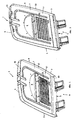
- the cover 1 shown in figure 1 is provided to cover a container (not shown) for containing a cooking fluid, which is in turn held in a fryer, body.
- this cover 1 has a substantially rectangular shape with two opposite transverse sides 4, 5 and two opposite longitudinal sides 2, 3.
- the cover 1 may however have also any other desired shape, such as for example square-shaped or round.
- the cover 1 is provided to cover a container (not shown) for containing a cooking fluid, e.g. frying fat or oil or any other cooking fluid deemed suitable by the person skilled in the art.
- the cover 1 comprises an outer wall 6 and an inner wall 7.
- the outer wall 6 comprises an inner face 12 facing the container, and an opposite outer face 22
- the inner wall 7 comprises an inner face 17 facing the container and an intermediate face 27 facing the inner face 12 of the outer wall 6.
- the inner wall 7 is preferably made of a heat-resistant material, such as for instance metal, whereas the outer wall 6 of the cover may also be made of metal or of any other material deemed suitable by the person skilled in the art, such as for example plastics for instance polyurethane or polypropylene.
- the inner side of the outer wall 6 is covered by the inner wall 7 over substantially the entire surface area.
- the inner face 12 of the outer wall 6 may comprise an uncovered part or a part 26 which is countersunk with respect to the rest of the inner face 12.
- the cover 1 is hingingly connectable to the container by means of a hinging connection 9.
- the hinging connection 9 is provided at a transverse side 5 of the cover 1. It is however also possible that the hinging connection 9 is provided at a longitudinal side 2, 3 of the cover 1.
- the hinging connection 9 comprises a first hinge part 19 and a second hinge part 29.
- the first hinge part 19 is connectable to, may be mounted to, integrated into or detachably connected to the cover 1, either directly or indirectly.
- the second hinge part 29 is connectable to the first hinge part 19 in view of forming the hinging connection 9.
- the second hinge part 29 is also connectable to the fryer body which holds the container (not shown).
- a reservoir 10 is provided as a condense collector. It is preferred that the condense collector 10 and the second hinge part 29 are made as one single piece. If so desired however, the condense collector may be or may comprise a collector which is removably mounted into the second hinge part or the fryer body.
- the reservoir 10 has an open top face which is open to the inner face 12, 17 of the cover 1 when opened.
- a preferred embodiment of this invention is characterised in that the first hinge part 19 of the hinging connection 9 is mounted to the inner face 12 of the outer wall 6 of the cover 1.
- the first hinge part 19 is mounted to uncovered part 26 of the inner face 12 of the outer wall 6 in the vicinity of the transverse side 5 of the cover 1.
- the first hinge part 19 may however also be mounted at any other suitable position on the cover 1, and may for instance be mounted on the inner face 17 of the inner wall 7.
- the condense collector 10 In the closed position of the cover, as shown in figure 1 and 6, at least part of the inner face 12 of the outer wall 6 is covered by the condense collector 10 (see below).
- the condense collector 10 will usually have a shape which is adapted to the shape of the cover in view of optimising condense collection.
- the condense collector of this invention is characterised in that it comprises a bottom 20 which is delimited in height direction of the condense collector by an upright wall 13, 14, 23, 24. The upright wall extends from the bottom 20 towards the cover 1, in the closed position of the cover 1.
- the condense collector 10 has a top face 30 which is preferably substantially open to the inner face 17 of the cover 1 in view of optimising condense collection.
- the top face 30 may however be partially covered, if the circumstances so require. In such case, the covered top face 30 may e.g. be perforated and the covering may be removably mounted in view of improving accessibility.
- the dimensions of the condense collector 10 and in particular of the top face 30 will usually be adapted by the person skilled in the art to guarantee optimum condense collection.
- the condense collector 10 is preferably substantially rectangular and comprises a bottom 20 delimited by opposite longitudinal 13, 14 upright side walls, and opposite transverse 23, 24 upright side walls extending between the longitudinal side walls 13, 14.
- the condense collector 10 may however also have any other shape.
- the longitudinal 13, 14 and transverse 23, 24 side walls point away from the bottom 20 of the condense collector 10 towards the inner face 12 of the cover 1 in a closed position of the cover 1.
- a condense collector is formed for collecting condense which has condensed against the inner face of the cover 1 and has, flown down along, the inner face 12, 17 of the cover in an at least partly open position of the cover 1.
- the longitudinal side wall 14 is inclined with respect to a plane perpendicular to the bottom 20. This is done to improve accessibility of the condense collector and to facilitate cleaning. However if so desired, the volume of the condense collector 10 may be further increased by having the longitudinal side walls 13, 14 slanting in a direction pointing away from each other.
- the bottom 20 may take any shape deemed convenient by the person skilled in the art.
- the bottom 20 of the condense collector 10 extends substantially parallel to the cover 1, but this is not an absolute requirement.
- the bottom may also slant with respect to the cover, or contain a gutter or any other means which could increase its water collecting capacity.
- the bottom 20 extends in line with the inner face 17 of the inner wall 7 in the closed position of the cover 1, and the longitudinal side wall 14 of the condense collector 10 is adjacent the side rim 15 of the inner wall 7 at a distance near the transverse side 5 of the cover 1.
- the condense collector 10 forms a shield protecting the first hinge part 19, mounted to the inner face 12 of the outer wall 6, against the deposition of fat or dirt during the cooking operation.
- the condense collector 10 may rest on an upper edge of the container (not shown) containing cooking fluid.
- the inner face of the cover 1 is formed by the inner face 17 of the inner wall 7 and the uncovered part 26 of the inner face 12 of the outer wall 6 or a recessed part of the inner wall 7.
- the outer 6 and inner 7 wall of the cover 1 may be provided at corresponding positions with openings extending throughout the thickness of the inner 7, respectively outer wall 6.
- part of the outer wall 6 of the cover 1 comprises of a plurality of parallel ribs 16 at regular distances from each other and extending in width direction of the cover 1 (not visible from figure 5). Between the ribs 16, elongated slots 25 extending in width direction of the cover 1 are present. At a corresponding position in the inner wall 7 of the cover 1, elongated slots 21 are present between ribs 17 forming the inner wall 7.
- the ribs 17 are preferably inclined with respect to a horizontal plane, thereby increasing the condensation surface of the inner wall 7 of the cover 1.
- a filter preferably a metal filter, is inserted for filtering the vapour escaping from the deep fat fryer into the environment.
- the filter also provides a condensation surface for evaporated oil or fat. It is however also possible to provide holes of any other type in any other way deemed suitable by the person skilled in the art, or that the inner 7 and outer 6 wall do not contain other which holes extend throughout the entire thickness of the inner 8 and outer wall 6.
- a window 8 may be provided in the cover 1, allowing the user to look into the interior of the deep fat fryer during the cooking operation.
- the first hinge part 19 comprises two pairs of clamps 18 which are spaced from each other in transverse direction of the cover (figure 7).
- the clamps 18 are mounted to the uncovered or recessed part 26 of the inner face 12 of the outer wall 6 of the cover 1. Between two pairs of clamps, a part 31 of the second hinge part 29 forming the hinging connection is received. In addition, each time between the clamps 18 of a pair of clamps a part 32 of the second hinge part 29 forming the hinging connection is received.
- Each pair of clamps 18 is connected to the adjacent part 32 and to part 31 of the second hinge part 29 by means of an axis extending throughout corresponding slots provided in the clamps 18 and the parts 32 and 31 of the second hinge part 29.
- the first 19 and second 29 hinge parts may however also be constructed in any other way deemed suitable by the man skilled in the art allowing hingingly connecting the first and second hinge part. It is for instance possible to provide the first and second hinge part 19, 29 with cooperating, complementary means which allows the second hinge part to be connected to the first hinge part by means of a click mechanism.
- the first 19 and second 29 hinge parts are hingeable with respect to each other between
- the longitudinal side wall 13 of the condense collector 10 may comprise the parts 31, 32 of the second hinge part 29 forming the hinging connection 9.
- the preferred embodiment shown in figure 1-6 is however characterised in that one or more of the parts 31, 32 protrude from the bottom wall 20 of the condense collector 10 towards the cover 1 in a closed position of the cover 1.
- the parts 31, 32 are mounted at a position between the opposite longitudinal side walls 13, 14 of the condense collector 10. In case the bottom 20 of the condense collector extends to a position corresponding to the side wall 5 of the cover 1, collection of condense flowing down the inner wall 7 of the cover 1, as well as the space between the inner and outer wall 6, 7 may be guaranteed.
- the condense collector will comprise an upright wall or protrusion which is aligned with the corresponding side wall 5 of the cover 1. In that way, the interior of the deep fat fryer may be well sealed from the environment in the closed position of the cover 1 (see figure 4).
- the parts 31, 32 of the second part 29 forming the hinging connection are preferably situated at a position above the condense collector 10 in height direction of the deep fat fryer.
- the risk that condense can flow off the cover along the outer wall of the container of the deep fat fryer in the open position of the cover may be minimised.
- the second hinge part 29 forming the hinging connection is not provided in the longitudinal side wall 13.
- the condense collector 10 is also situated at a position below the first hinge part 19 in height direction of the deep fat fryer in any position of the cover.
- Figures 1-6 further show that the condense collector 10 extends along substantially the entire transverse side 5 of the cover 1, and that longitudinal side walls 13, 14 of the condense collector 10 preferably extend substantially parallel to the transverse side 5 of the cover comprising the first hinge part 19.
- the condensation water formed on the entire inner face 17 of the inner wall 7 of the cover 1 over the entire width thereof can be collected into the condense collector 10 in the at least partly open position of the cover 1.
- first 19 and second 29 hinge parts are dimensioned and mounted with respect to each other and to the cover in such a way that, in the open position of the cover, the first hinge part 19 is covered by the second hinge part 29 together with the outer wall of the cover (not visible form the figures). As such, vapour condensed on an outer face of the cover is prevented from flowing down along the outer face of the cover and onto the first hinge part in the open position of the cover.
- the second hinge part 29 is preferably removably mountable to the fryer body. This may be achieved in various ways.
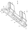
- the second hinge part 29 of the hinging connection 9 comprises one, two or more protrusions 28 protruding from the condense collector 10 towards the fryer body, as shown in figure 7.
- the protrusions 28 are provided to be removably mounted in a corresponding holder mounted to the body of the deep fat fryer (not shown).
- the holder may be formed in the wall of the body.
- the second hinge part 29 of the hinging connection 9 may be constructed in any other way deemed suitable to the man skilled in the art in view of achieving a removable mounting to the fryer body.
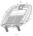
- the cover 40 has a somewhat more rounded rectangular shape than the cover 1, but this is merely a design with no functional difference.
- the main difference in the embodiment of figures 8-11 is in the condense collector 50, which is shown in more detail in figure 12.
- the condense collector 50 comprises the second hinge part 29, formed by two upstanding hinge parts 51 which connect to the first hinge part 19 on the cover 40, and two downwardly depending protrusions 28 for removably mounting the condense collector 50 on the fryer body. Condense is collected in the reservoir formed by the walls 13, 14, 23 and 24 and the bottom 20 with an open top face 30.
- the condense collector 50 shown in figure 7 is a single piece moulded body in a plastic material.
- the collector 50 may however also be constructed in other materials and the collector 50 and the second hinge part 29 may be constructed as separate parts, which may or may not be attachable to each other.
- the single piece construction is however preferred, since the condense collector 50 is then removed from the fryer body along with the cover and can therefore easily be emptied and cleaned by the user.
- the open top face 30 of the condense collector 50 is closed off from the container space by the inner face 17 of the cover 40 when closed, but open towards the outside at the rear wall 13 so that the collected condense can evaporate towards the outside of the deep fat fryer during a subsequent cooking operation.
- An additional feature of the condense collector 50 which is not present on the condense collector 10 of figures 1-7 is the drip ridge 52 on the bottom side 20. This drip ridge 52 extends in front of and follows the upper rim 53 of the inner side wall of the container 55.
- condense on the front wall 13 of the condense collector can flow down and drip from the drip ridge 52 back into the container space, instead of entering the narrow gap between the condense collector 50 and the upper rim 53 of the inner side wall of the container as a result of capillary action.
Landscapes
- Engineering & Computer Science (AREA)
- Food Science & Technology (AREA)
- Frying-Pans Or Fryers (AREA)
Priority Applications (1)
| Application Number | Priority Date | Filing Date | Title |
|---|---|---|---|
| EP05447026A EP1563778A1 (fr) | 2004-02-17 | 2005-02-14 | Friteuse |
Applications Claiming Priority (3)
| Application Number | Priority Date | Filing Date | Title |
|---|---|---|---|
| EP04447044 | 2004-02-17 | ||
| EP04447044A EP1563777A1 (fr) | 2004-02-17 | 2004-02-17 | Friteuse |
| EP05447026A EP1563778A1 (fr) | 2004-02-17 | 2005-02-14 | Friteuse |
Publications (1)
| Publication Number | Publication Date |
|---|---|
| EP1563778A1 true EP1563778A1 (fr) | 2005-08-17 |
Family
ID=34702394
Family Applications (1)
| Application Number | Title | Priority Date | Filing Date |
|---|---|---|---|
| EP05447026A Withdrawn EP1563778A1 (fr) | 2004-02-17 | 2005-02-14 | Friteuse |
Country Status (1)
| Country | Link |
|---|---|
| EP (1) | EP1563778A1 (fr) |
Cited By (1)
| Publication number | Priority date | Publication date | Assignee | Title |
|---|---|---|---|---|
| WO2007115784A1 (fr) * | 2006-04-12 | 2007-10-18 | De'longhi S.P.A. | Friteuse |
Citations (5)
| Publication number | Priority date | Publication date | Assignee | Title |
|---|---|---|---|---|
| GB1297801A (fr) * | 1969-11-19 | 1972-11-29 | ||
| EP0026958A1 (fr) * | 1979-10-09 | 1981-04-15 | Itt Industries, Inc. | Récipient de cuisson avec couvercle |
| EP0028190A1 (fr) * | 1979-10-25 | 1981-05-06 | Seb S.A. | Ustensile culinaire comportant des moyens pour collecter les condensats de vapeur |
| DE3150455A1 (de) * | 1981-12-19 | 1983-06-30 | Robert Krups Stiftung & Co KG, 5650 Solingen | Friteuse mit einem elektrisch beheizbaren fritiertopf |
| GB2205731A (en) * | 1987-06-06 | 1988-12-21 | Swan Housewares Ltd | Electrically heated cooking appliance |
-
2005
- 2005-02-14 EP EP05447026A patent/EP1563778A1/fr not_active Withdrawn
Patent Citations (5)
| Publication number | Priority date | Publication date | Assignee | Title |
|---|---|---|---|---|
| GB1297801A (fr) * | 1969-11-19 | 1972-11-29 | ||
| EP0026958A1 (fr) * | 1979-10-09 | 1981-04-15 | Itt Industries, Inc. | Récipient de cuisson avec couvercle |
| EP0028190A1 (fr) * | 1979-10-25 | 1981-05-06 | Seb S.A. | Ustensile culinaire comportant des moyens pour collecter les condensats de vapeur |
| DE3150455A1 (de) * | 1981-12-19 | 1983-06-30 | Robert Krups Stiftung & Co KG, 5650 Solingen | Friteuse mit einem elektrisch beheizbaren fritiertopf |
| GB2205731A (en) * | 1987-06-06 | 1988-12-21 | Swan Housewares Ltd | Electrically heated cooking appliance |
Cited By (2)
| Publication number | Priority date | Publication date | Assignee | Title |
|---|---|---|---|---|
| WO2007115784A1 (fr) * | 2006-04-12 | 2007-10-18 | De'longhi S.P.A. | Friteuse |
| CN101420894B (zh) * | 2006-04-12 | 2011-05-11 | 德隆奇有限公司 | 煎炸锅 |
Similar Documents
| Publication | Publication Date | Title |
|---|---|---|
| US5584234A (en) | Cooking appliance, such as a fryer for example, having a condensation device for cooking vapours | |
| KR100350327B1 (ko) | 식품 프라이장치 | |
| KR101294112B1 (ko) | 전기밥솥의 물받이 구조체 | |
| CN116138629A (zh) | 收集盆以及具有收集盆的烤炉 | |
| EP1813175A1 (fr) | Poele perfectionnee | |
| EP1563778A1 (fr) | Friteuse | |
| EP2730706A1 (fr) | Appareil de clapet à eau | |
| US5497814A (en) | Invertible no waste funnel | |
| EP1563777A1 (fr) | Friteuse | |
| IES20070885A2 (en) | A container | |
| KR20040013820A (ko) | 냉장고의 디스펜스부 | |
| KR100747630B1 (ko) | 전기압력밥솥 | |
| KR200438974Y1 (ko) | 전기압력밥솥 | |
| US7530468B1 (en) | Drinking apparatus | |
| US20080141586A1 (en) | Universal plant pot base | |
| KR100793408B1 (ko) | 전기압력밥솥 | |
| KR200362260Y1 (ko) | 양면후라이팬 | |
| KR20090033570A (ko) | 배수 트랩을 포함하는 싱크대 | |
| JP2009011498A (ja) | 塵取り | |
| KR20180068631A (ko) | 압력밥솥 | |
| CN218178995U (zh) | 一种集油结构及台式净烟机 | |
| CN103069231A (zh) | 具有用于接收滴下的冷凝水的倾倒装置的制冷设备 | |
| KR200434676Y1 (ko) | 전기압력밥솥 | |
| KR200410949Y1 (ko) | 양면 프라이팬 | |
| KR200434684Y1 (ko) | 전기압력밥솥 |
Legal Events
| Date | Code | Title | Description |
|---|---|---|---|
| PUAI | Public reference made under article 153(3) epc to a published international application that has entered the european phase |
Free format text: ORIGINAL CODE: 0009012 |
|
| AK | Designated contracting states |
Kind code of ref document: A1 Designated state(s): AT BE BG CH CY CZ DE DK EE ES FI FR GB GR HU IE IS IT LI LT LU MC NL PL PT RO SE SI SK TR |
|
| AX | Request for extension of the european patent |
Extension state: AL BA HR LV MK YU |
|
| AKX | Designation fees paid | ||
| REG | Reference to a national code |
Ref country code: DE Ref legal event code: 8566 |
|
| STAA | Information on the status of an ep patent application or granted ep patent |
Free format text: STATUS: THE APPLICATION IS DEEMED TO BE WITHDRAWN |
|
| 18D | Application deemed to be withdrawn |
Effective date: 20060218 |