EP1563783A2 - Filteranordnung für einen Staubsauger und Staubsauger mit einer solchen Filteranordnung - Google Patents
Filteranordnung für einen Staubsauger und Staubsauger mit einer solchen Filteranordnung Download PDFInfo
- Publication number
- EP1563783A2 EP1563783A2 EP05001311A EP05001311A EP1563783A2 EP 1563783 A2 EP1563783 A2 EP 1563783A2 EP 05001311 A EP05001311 A EP 05001311A EP 05001311 A EP05001311 A EP 05001311A EP 1563783 A2 EP1563783 A2 EP 1563783A2
- Authority
- EP
- European Patent Office
- Prior art keywords
- filter assembly
- body portion
- vacuum cleaner
- assembly
- filter
- Prior art date
- Legal status (The legal status is an assumption and is not a legal conclusion. Google has not performed a legal analysis and makes no representation as to the accuracy of the status listed.)
- Granted
Links
Images





Classifications
-
- A—HUMAN NECESSITIES
- A47—FURNITURE; DOMESTIC ARTICLES OR APPLIANCES; COFFEE MILLS; SPICE MILLS; SUCTION CLEANERS IN GENERAL
- A47L—DOMESTIC WASHING OR CLEANING; SUCTION CLEANERS IN GENERAL
- A47L9/00—Details or accessories of suction cleaners, e.g. mechanical means for controlling the suction or for effecting pulsating action; Storing devices specially adapted to suction cleaners or parts thereof; Carrying-vehicles specially adapted for suction cleaners
- A47L9/10—Filters; Dust separators; Dust removal; Automatic exchange of filters
- A47L9/102—Dust separators
-
- A—HUMAN NECESSITIES
- A47—FURNITURE; DOMESTIC ARTICLES OR APPLIANCES; COFFEE MILLS; SPICE MILLS; SUCTION CLEANERS IN GENERAL
- A47L—DOMESTIC WASHING OR CLEANING; SUCTION CLEANERS IN GENERAL
- A47L5/00—Structural features of suction cleaners
- A47L5/12—Structural features of suction cleaners with power-driven air-pumps or air-compressors, e.g. driven by motor vehicle engine vacuum
- A47L5/22—Structural features of suction cleaners with power-driven air-pumps or air-compressors, e.g. driven by motor vehicle engine vacuum with rotary fans
- A47L5/24—Hand-supported suction cleaners
-
- A—HUMAN NECESSITIES
- A47—FURNITURE; DOMESTIC ARTICLES OR APPLIANCES; COFFEE MILLS; SPICE MILLS; SUCTION CLEANERS IN GENERAL
- A47L—DOMESTIC WASHING OR CLEANING; SUCTION CLEANERS IN GENERAL
- A47L9/00—Details or accessories of suction cleaners, e.g. mechanical means for controlling the suction or for effecting pulsating action; Storing devices specially adapted to suction cleaners or parts thereof; Carrying-vehicles specially adapted for suction cleaners
- A47L9/10—Filters; Dust separators; Dust removal; Automatic exchange of filters
- A47L9/12—Dry filters
- A47L9/125—Dry filters funnel-shaped
-
- Y—GENERAL TAGGING OF NEW TECHNOLOGICAL DEVELOPMENTS; GENERAL TAGGING OF CROSS-SECTIONAL TECHNOLOGIES SPANNING OVER SEVERAL SECTIONS OF THE IPC; TECHNICAL SUBJECTS COVERED BY FORMER USPC CROSS-REFERENCE ART COLLECTIONS [XRACs] AND DIGESTS
- Y10—TECHNICAL SUBJECTS COVERED BY FORMER USPC
- Y10S—TECHNICAL SUBJECTS COVERED BY FORMER USPC CROSS-REFERENCE ART COLLECTIONS [XRACs] AND DIGESTS
- Y10S55/00—Gas separation
- Y10S55/03—Vacuum cleaner
Definitions
- the present invention relates to filter assemblies for vacuum cleaners, and to vacuum cleaners incorporating such filter assemblies.
- the invention relates particularly, but not exclusively, to filter assemblies for handheld vacuum cleaners, and to handheld vacuum cleaners incorporating such assemblies.
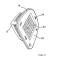
- a filter apparatus of a vacuum cleaner of this type is shown in Figures 1 to 4.
- a vacuum cleaner 2 has a housing 4 containing a motor (not shown) for driving a fan (not shown) having an air inlet 6.
- a filter apparatus 8 includes a coarse filter assembly 10 having a cup-shaped body 12 having apertures 14, and a resilient rubber seal 16 is provided around the periphery of the body 12.
- a pair of apertures 18, each of which comprises a smaller portion 20 and a larger portion 22, are provided on opposite sides of the periphery of the body 12, and resilient rubber seals 24 surround each aperture 18.
- a fine filter assembly 26 comprises a body 28 having a shape corresponding to that of coarse filter assembly 10 and has a central aperture 30 in which a pleated filter element 32 of suitable fibrous material which will be familiar to persons skilled in the art is arranged.
- a pair of apertures 34 corresponding in shape to the apertures 18 at the periphery of coarse filter assembly 10, are provided on opposite sides of the periphery of body 28.
- the fine filter element 32 of the fine filter assembly 26 is placed inside the coarse filter assembly 10 such that apertures 34 overlie apertures 18, and the apertures 18, 34 are placed over corresponding pins 36 on housing 4.
- the pins 36 have enlarged heads which pass through the wider portions 22 of apertures 18, and the coarse filter assembly 10 is then rotated slightly relative to housing 4 to engage the shaft of pins 36 with the narrow portions 20 of apertures 18 to prevent removal of the coarse filter assembly 10, and thereby also of the fine filter assembly 26, from the housing 4. In this way, air entering into air inlet 6 is forced to pass through coarse filter assembly 10 and fine filter assembly 26 before it reaches the fan of the vacuum cleaner.
- Preferred embodiments of the present invention seek to overcome the above disadvantages of the prior art.
- a first filter assembly for a vacuum cleaner having a housing, at least one air inlet, at least one air outlet, and suction means for causing air to flow from at least one said inlet to at least one said outlet, the filter assembly comprising:-
- first filter assembly having second mounting means for enabling a second filter assembly to be removably mounted to the body portion of the first filter assembly
- this provides the advantage of enabling a user of a vacuum cleaner incorporating the first filter assembly to choose between two stage filtration, i.e. by means of the first and second filter assemblies, or one stage filtration, i.e. by means of the first filter assembly only.
- the first filter assembly may be a fine filter assembly
- the second filter assembly may be a coarse filter assembly.
- the first mounting means may comprise at least one aperture and/or protrusion on said body portion adapted to engage a respective protrusion and/or aperture on the housing.
- At least one said aperture may comprise a first portion for enabling removal of the aperture from the corresponding said protrusion when engaged therewith, and a second portion, narrower than said first portion, for preventing removal of the aperture from the corresponding said protrusion when engaged therewith.
- the sealing means may surround the or each said aperture and/or protrusion of said first mounting means.
- the first mounting means may comprise a plurality of said apertures and/or protrusions circumferentially spaced around said body portion radially outwards of the or each said first aperture.
- This provides the advantage of providing a stable mounting of the body portion to the housing of the vacuum cleaner.
- the second mounting means may comprise at least one aperture and/or projection on said body portion for engaging a respective projection and/or aperture on the second filter assembly.
- Said second mounting means may comprise at least one slot and/or protrusion on said body portion for engaging a respective said protrusion and/or slot on the second filter assembly.
- the sealing means may comprise at least one resilient member surrounding the or each said first aperture.
- the sealing means may comprise a single said resilient member surrounding the or each said first aperture.
- the first mounting means may be shaped and/or sized and/or spaced around said body portion so as to prevent the second filter assembly from being mounted thereto.
- the second mounting means may be shaped and/or sized and/or spaced around said body portion so as to prevent the second filter assembly from being mounted directly to the housing of the vacuum cleaner.
- This provides the advantage of preventing the second filter assembly from being mounted directly to the housing of the vacuum cleaner, which could result in damage to the motor of the vacuum cleaner as a result of intake of insufficiently filtered air in the case where the first filter assembly is a fine filter and the second filter assembly is a coarse filter.
- the assembly may further comprise third mounting means for enabling at least one third filter assembly to be removably mounted to said first filter assembly for preventing entry of air into the second filter assembly without previously having passed through the third filter assembly.
- the third mounting means may be shaped and/or sized and/or spaced around said body portion so as to prevent the third filter assembly from being mounted directly to the housing of the vacuum cleaner.
- a second filter assembly for a vacuum cleaner having a housing, at least one air inlet, at least one air outlet, and suction means for causing air to flow from at least one said inlet to at least one said outlet, the filter assembly comprising:-
- this provides the advantage that the second filter assembly can be removed, while leaving the first filter assembly in place mounted to the housing of a vacuum cleaner incorporating the filter assembly.
- This provides the advantage of giving the user a choice between one stage filtration (i.e. by means of the first filter assembly only) or two-stage filtration (i.e. by means of the first and second filter assemblies).
- the first mounting means may comprise a plurality of protrusions and/or apertures on said body portion adapted to engage respective apertures and/or protrusions on the first filter assembly.
- the first mounting means may comprise at least one slot and/or protrusion on said body portion for engaging a respective said protrusion and/or slot on the first filter assembly.
- the assembly may further comprise third mounting means for enabling at least one third filter assembly to be removably mounted to said second filter assembly for preventing entry of air into the second filter assembly without previously having passed through the third filter assembly.
- the third mounting means may be shaped and/or sized and/or spaced around said body portion so as to prevent the third filter assembly from being mounted directly to the housing of the vacuum cleaner.
- a filter apparatus for a vacuum deaner having a housing, at least one air inlet, at least one air outlet, and suction means for causing air to flow from at least one said inlet to at least one said outlet, the filter apparatus comprising:-
- the apparatus may comprise a first filter assembly as defined above and a second filter assembly as defined above.
- the apparatus may comprise at least one third filter assembly adapted to be removably mounted to said first and/or said second filter assembly for preventing entry of air into the second filter assembly without previously having passed through the third filter assembly.
- the third filter assembly may comprise fourth mounting means for enabling said third filter assembly to be removably mounted to said first and/or second filter assembly.
- the fourth mounting means may be shaped and/or sized and/or spaced around said body portion so as to prevent the third filter assembly from being mounted directly to the housing of the vacuum cleaner.
- a vacuum cleaner comprising a housing, at least one air inlet, at least one air outlet, suction means for causing air to flow from at least one said inlet to at least one said outlet, and a filter apparatus as defined above arranged between the or each said inlet and said suction means.
- a vacuum cleaner 102 has a housing 104 and a handle 106.
- the housing contains a motor (not shown) which can be actuated by means of trigger switch 108 to operate a fan 110 arranged inside air inlet 112.
- the housing 104 is provided with a set of circumferentially spaced pins 114 arranged radially outwards of air inlet 112, each of the pins 114 having a shaft and an enlarged head.
- a filter apparatus 120 comprises a first, fine filter assembly 122 ( Figure 8) and a second, coarse filter assembly 124 ( Figure 9).
- fine filter assembly 122 comprises a body 130 moulded from durable plastics material and defining a central aperture 132 in which a pleated fine filter element (not shown) of suitable fibrous material which will be familiar to persons skilled in the art is arranged.
- aperture 132 The periphery of aperture 132 is surrounded by a resilient sealing member 134, which is integrally moulded with body 130 and the purpose of which will be described in greater detail below, and three apertures 136, each of which comprises a wider portion 138 and a narrower portion 140, are circumferentially arranged around body portion 130 radially outwards of aperture 132 and sealing member 134.
- the body 130 is also provided with radially inwardly facing slots 142 circumferentially arranged around body portion 130 radially outwards of aperture 132 and sealing member 134. The purpose of slots 142 will be described in greater detail below.
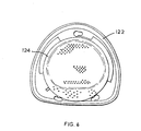
- coarse filter assembly 124 comprises a cup shaped body 149 having an end wall 150 and side walls 151, the end wall 150 and side walls 151 having apertures (not shown) therethrough for allowing intake of air.
- a series of peripheral protrusions 152 are arranged adjacent peripheral cut outs 154.
- the body portion 149 is shaped to receive fine filter assembly 122, and the coarse filter assembly 124 is mounted to the fine filter assembly 122 by placing the central part of fine filter assembly 122 (i.e. that part containing the fine filter element) inside body portion 149 of coarse filter assembly 124 such that apertures 136 of fine filter assembly 122 overlie cut outs 154 of coarse filter assembly 124.
- the filter assemblies 122, 124 are then rotated slightly relative to each other so that protrusions 152 of coarse filter assembly 124 are located within slots 142 on body portion 130 of fine filter assembly 122.
- the assembled filter apparatus 120 can then be mounted to housing 104 by passing the heads of pins 114 through the corresponding wider portions 138 of apertures 136 to place sealing member 134 under compression, and then rotating fine filter assembly 122 slightly relative to housing 104 to engage pins 114 with the narrower portions 140 of apertures 138 to prevent removal of the filter apparatus 120 from housing 104.
- the user mounts the filter apparatus 120 comprising fine filter assembly 122 and coarse filter assembly 124 to housing 104 by engaging apertures 136 of fine filter assembly body portion 130 with pins 114 on housing 104.
- the sealing member 134 is placed under compression and held under compression by engagement of the heads of pins 114 with the sides of apertures 136.
- the motor is actuated by means of trigger switch 108, the fan 110 draws air into air inlet 112. Because the periphery of air inlet 112 is sealed by means of sealing member 134 placed under compression by engagement of apertures 136 with pins 114, only air having passed through coarse filter assembly 124 and fine filter assembly 122 can enter air inlet 112.
- the coarse filter assembly 124 is dismounted from fine filter assembly 122 by rotating coarse filter assembly 124 relative to fine filter assembly 122 so that protrusions 152 are disengaged from slots 142 to allow removal of coarse filter assembly 124.
- fan 110 is actuated, because the sealing member 134 surrounding air inlet 112 is still under compression as a result of the engagement of heads of pins 114 with the periphery of narrow portions 140 of apertures 136, air cannot enter air inlet 112 without first passing through the fine filter element of fine filter assembly 122.
- the pins 114 on the housing 104 and the protrusions 152 of coarse filter assembly 124 are shaped such that the coarse filter assembly 124 cannot be directly mounted to the housing 104 in the absence of fine filter assembly 122, but can only be mounted to fine filter assembly 122. This prevents a user from being able to operate the vacuum cleaner with only coarse filter assembly 124 mounted to housing 104, which would damage the motor of the vacuum cleaner as a result of insufficiently filtered air passing into air inlet 112.
- the third and subsequent filter assemblies can have various degrees of fineness of filtration, for example less fine than fine filter assembly 122, and more or less fine than coarse filter assembly 124. Again, it will be appreciated by persons skilled in the art that in a manner similar to coarse filter assembly 124, the third and subsequent filter assemblies may be provided with fittings to prevent them from being directly mounted to the pins 114 on housing 104, to prevent operation of the vacuum cleaner when fine filter assembly 122 is not present, thus minimising the risk of damage to the motor.
Landscapes
- Engineering & Computer Science (AREA)
- Mechanical Engineering (AREA)
- Filters For Electric Vacuum Cleaners (AREA)
- Filtering Of Dispersed Particles In Gases (AREA)
Applications Claiming Priority (2)
| Application Number | Priority Date | Filing Date | Title |
|---|---|---|---|
| GB0402847 | 2004-02-10 | ||
| GBGB0402847.8A GB0402847D0 (en) | 2004-02-10 | 2004-02-10 | Filter assembly for vacuum cleaner and vacuum cleaner incorporating such assembly |
Publications (3)
| Publication Number | Publication Date |
|---|---|
| EP1563783A2 true EP1563783A2 (de) | 2005-08-17 |
| EP1563783A3 EP1563783A3 (de) | 2006-04-05 |
| EP1563783B1 EP1563783B1 (de) | 2009-06-10 |
Family
ID=32011589
Family Applications (1)
| Application Number | Title | Priority Date | Filing Date |
|---|---|---|---|
| EP05001311A Expired - Lifetime EP1563783B1 (de) | 2004-02-10 | 2005-01-24 | Filteranordnung für einen Staubsauger und Staubsauger mit einer solchen Filteranordnung |
Country Status (6)
| Country | Link |
|---|---|
| US (1) | US7572307B2 (de) |
| EP (1) | EP1563783B1 (de) |
| CN (1) | CN1653999B (de) |
| AT (1) | ATE433296T1 (de) |
| DE (1) | DE602005014820D1 (de) |
| GB (1) | GB0402847D0 (de) |
Cited By (3)
| Publication number | Priority date | Publication date | Assignee | Title |
|---|---|---|---|---|
| ES2259489A1 (es) * | 2002-11-25 | 2006-10-01 | Samsung Gwangju Electronics Co., Ltd. | Filtro colector de polvo para aspirador y aspirador provisto de dicho filtro. |
| GB2440515A (en) * | 2006-08-01 | 2008-02-06 | Dyson Technology Ltd | A filter assembly |
| GB2440514A (en) * | 2006-08-01 | 2008-02-06 | Dyson Technology Ltd | A filter assembly |
Families Citing this family (21)
| Publication number | Priority date | Publication date | Assignee | Title |
|---|---|---|---|---|
| SE0300355D0 (sv) | 2003-02-10 | 2003-02-10 | Electrolux Ab | Hand held vacuum cleaner |
| USD553228S1 (en) * | 2005-07-29 | 2007-10-16 | Resmed Limited | Humidifier tub inlet box seal |
| SE0600668L (sv) * | 2006-03-24 | 2007-10-23 | Electrolux Abp | Handhållen dammsugare |
| USD577109S1 (en) | 2006-04-05 | 2008-09-16 | Resmed Limited | Adaptor seal |
| CN101460083B (zh) * | 2006-04-10 | 2014-08-13 | 伊莱克斯公司 | 真空吸尘器 |
| US8424154B2 (en) | 2006-04-10 | 2013-04-23 | Ab Electrolux | Vacuum cleaner with filter cleaning means |
| SE531125C2 (sv) * | 2007-01-19 | 2008-12-23 | Electrolux Ab | Förbättringar med avseende på luftströmningsförluster i en dammsugare |
| US20080040883A1 (en) * | 2006-04-10 | 2008-02-21 | Jonas Beskow | Air Flow Losses in a Vacuum Cleaners |
| US8402601B2 (en) * | 2007-01-23 | 2013-03-26 | AB Electronlux | Vacuum cleaner nozzle |
| US7854781B2 (en) * | 2007-04-30 | 2010-12-21 | International Business Machines Corporation | Mount for air filter and bezel assembly |
| US7979957B2 (en) * | 2008-11-04 | 2011-07-19 | Meyer Gretchen A | Apparatus for collecting lightweight packing particulates |
| KR102024591B1 (ko) * | 2012-11-14 | 2019-11-04 | 엘지전자 주식회사 | 로봇 청소기 |
| DE112017001802T5 (de) | 2016-03-31 | 2019-01-03 | Lg Electronics Inc. | Reinigungsvorrichtung |
| US10638903B2 (en) * | 2016-03-31 | 2020-05-05 | Lg Electronics Inc. | Cleaner |
| AU2017101264A4 (en) | 2016-09-29 | 2017-10-26 | Bissell Inc. | Vacuum cleaner |
| US11337570B2 (en) | 2016-10-07 | 2022-05-24 | Aktiebolaget Electrolux | Stick vacuum cleaner with improved filter |
| US11930987B2 (en) * | 2018-04-20 | 2024-03-19 | Omachron Intellectual Property Inc. | Surface cleaning apparatus |
| EP3566627A1 (de) * | 2018-05-09 | 2019-11-13 | Hilti Aktiengesellschaft | Luftausblassystem für einen tragbaren trockensauger |
| CN110464248B (zh) * | 2018-05-10 | 2021-10-22 | 比亚迪股份有限公司 | 集尘组件、尘气处理装置、吸尘器及扫地机器人 |
| CN111689594A (zh) * | 2019-03-13 | 2020-09-22 | 佛山市顺德区美的饮水机制造有限公司 | 净水器和用于净水器的进气过滤装置 |
| EP4559367B1 (de) | 2022-07-07 | 2026-04-22 | BISSELL Inc. | Modulares kopfsystem für handstaubsauger, trockenstaubsaugerzubehör für handstaubsauger und handstaubsauger |
Family Cites Families (18)
| Publication number | Priority date | Publication date | Assignee | Title |
|---|---|---|---|---|
| US4213224A (en) * | 1978-08-21 | 1980-07-22 | Shop-Vac Corporation | By-pass type portable vacuum cleaner |
| US4592764A (en) * | 1983-06-30 | 1986-06-03 | Sharp Kabushiki Kaisha | Vacuum cleaner |
| CN85201887U (zh) * | 1985-05-20 | 1986-03-12 | 夏普公司 | 真空吸尘器 |
| US4831685B1 (en) * | 1987-11-27 | 1995-05-09 | Hoover Co | Wet and dry vacuum cleaner |
| GB2305113B (en) | 1995-09-16 | 1999-10-27 | Neil Kenneth Weatherill | Compact vacuum cleaner |
| US6110248A (en) | 1998-08-31 | 2000-08-29 | Shop Vac Corporation | Dual filter assembly for a vacuum cleaner |
| US6314610B1 (en) * | 1999-04-23 | 2001-11-13 | The Hoover Company | Vacuum cleaner bag housing assembly |
| GB9916759D0 (en) * | 1999-07-17 | 1999-09-15 | Black & Decker Inc | Improvements in vacuum cleaners |
| US6434785B1 (en) | 2000-04-19 | 2002-08-20 | Headwaters Research & Development, Inc | Dual filter wet/dry hand-held vacuum cleaner |
| KR100424581B1 (ko) * | 2001-12-20 | 2004-03-27 | 엘지전자 주식회사 | 진공청소기의 배기필터 체결장치 |
| KR100437116B1 (ko) * | 2002-05-22 | 2004-06-23 | 삼성광주전자 주식회사 | 진공청소기 |
| US7260867B2 (en) * | 2002-10-11 | 2007-08-28 | Panasonic Corporation Of North America | Bagless dust box for vacuum cleaner |
| US7185394B2 (en) * | 2002-11-07 | 2007-03-06 | Panasonic Corporation Of North America | Dirt cup assembly with attachable and detachable external filter holder |
| KR100485705B1 (ko) * | 2003-02-21 | 2005-04-28 | 삼성광주전자 주식회사 | 진공청소기용 집진통 |
| JP3528847B1 (ja) * | 2003-03-03 | 2004-05-24 | 松下電器産業株式会社 | 電気掃除機 |
| KR100587099B1 (ko) * | 2003-05-10 | 2006-06-07 | 엘지전자 주식회사 | 사이클론 방식 진공 청소기의 집진 유니트 |
| US7135051B2 (en) * | 2003-06-05 | 2006-11-14 | Baldinger Russell L | Dirt cup filter with pre-filtration cap |
| KR100564450B1 (ko) * | 2003-07-09 | 2006-03-29 | 엘지전자 주식회사 | 진공 청소기 집진 유니트의 장착 구조 |
-
2004
- 2004-02-10 GB GBGB0402847.8A patent/GB0402847D0/en not_active Ceased
-
2005
- 2005-01-24 AT AT05001311T patent/ATE433296T1/de not_active IP Right Cessation
- 2005-01-24 DE DE602005014820T patent/DE602005014820D1/de not_active Expired - Lifetime
- 2005-01-24 EP EP05001311A patent/EP1563783B1/de not_active Expired - Lifetime
- 2005-01-31 US US11/047,405 patent/US7572307B2/en not_active Expired - Fee Related
- 2005-02-07 CN CN2005100076726A patent/CN1653999B/zh not_active Expired - Fee Related
Cited By (5)
| Publication number | Priority date | Publication date | Assignee | Title |
|---|---|---|---|---|
| ES2259489A1 (es) * | 2002-11-25 | 2006-10-01 | Samsung Gwangju Electronics Co., Ltd. | Filtro colector de polvo para aspirador y aspirador provisto de dicho filtro. |
| ES2259489B1 (es) * | 2002-11-25 | 2007-09-16 | Samsung Gwangju Electronics Co., Ltd. | Filtro colector de polvo para aspirador y aspirador provisto de dicho filtro. |
| GB2440515A (en) * | 2006-08-01 | 2008-02-06 | Dyson Technology Ltd | A filter assembly |
| GB2440514A (en) * | 2006-08-01 | 2008-02-06 | Dyson Technology Ltd | A filter assembly |
| GB2440515B (en) * | 2006-08-01 | 2011-06-15 | Dyson Technology Ltd | A filter assembly |
Also Published As
| Publication number | Publication date |
|---|---|
| CN1653999A (zh) | 2005-08-17 |
| CN1653999B (zh) | 2010-04-28 |
| EP1563783B1 (de) | 2009-06-10 |
| ATE433296T1 (de) | 2009-06-15 |
| DE602005014820D1 (de) | 2009-07-23 |
| EP1563783A3 (de) | 2006-04-05 |
| US7572307B2 (en) | 2009-08-11 |
| US20050183406A1 (en) | 2005-08-25 |
| GB0402847D0 (en) | 2004-03-17 |
Similar Documents
| Publication | Publication Date | Title |
|---|---|---|
| US7572307B2 (en) | Filter assembly for vacuum cleaner and vacuum cleaner incorporating such assembly | |
| KR101606890B1 (ko) | 디퓨저유닛을 구비한 진공청소기의 팬모터 장치 | |
| KR101164392B1 (ko) | 공기 처리 시스템 | |
| CN111853992B (zh) | 空气清洁器 | |
| EP3609379B1 (de) | Zyklonabscheider und handstaubsauger | |
| US9089248B2 (en) | Fan motor apparatus having diffuser unit for vacuum cleaner | |
| US7105035B2 (en) | Cyclone-type dust collecting apparatus for vacuum cleaner | |
| US5853445A (en) | Interlocking dual filter | |
| CN111853993B (zh) | 空气清洁器 | |
| KR101861012B1 (ko) | 공기 청정기 | |
| KR20190044044A (ko) | 공기 청정기 | |
| KR20180041058A (ko) | 공기 청정기 | |
| KR20030058054A (ko) | 이중 필터링 기능을 가지는 진공청소기 | |
| KR100222843B1 (ko) | 진공청소기의 배기구조 | |
| HK1161702B (en) | Air treatment system | |
| HK1161701A (en) | Air treatment system | |
| KR20170000957U (ko) | 개인이 휴대하여 사용 가능한 필터식 공기청정기 | |
| HK1161699A (en) | Air treatment system | |
| HK1161700B (en) | Air treatment system | |
| HK1106454B (en) | Air treatment system |
Legal Events
| Date | Code | Title | Description |
|---|---|---|---|
| PUAI | Public reference made under article 153(3) epc to a published international application that has entered the european phase |
Free format text: ORIGINAL CODE: 0009012 |
|
| AK | Designated contracting states |
Kind code of ref document: A2 Designated state(s): AT BE BG CH CY CZ DE DK EE ES FI FR GB GR HU IE IS IT LI LT LU MC NL PL PT RO SE SI SK TR |
|
| AX | Request for extension of the european patent |
Extension state: AL BA HR LV MK YU |
|
| PUAL | Search report despatched |
Free format text: ORIGINAL CODE: 0009013 |
|
| AK | Designated contracting states |
Kind code of ref document: A3 Designated state(s): AT BE BG CH CY CZ DE DK EE ES FI FR GB GR HU IE IS IT LI LT LU MC NL PL PT RO SE SI SK TR |
|
| AX | Request for extension of the european patent |
Extension state: AL BA HR LV MK YU |
|
| 17P | Request for examination filed |
Effective date: 20060428 |
|
| AKX | Designation fees paid |
Designated state(s): AT BE BG CH CY CZ DE DK EE ES FI FR GB GR HU IE IS IT LI LT LU MC NL PL PT RO SE SI SK TR |
|
| 17Q | First examination report despatched |
Effective date: 20070315 |
|
| GRAP | Despatch of communication of intention to grant a patent |
Free format text: ORIGINAL CODE: EPIDOSNIGR1 |
|
| GRAS | Grant fee paid |
Free format text: ORIGINAL CODE: EPIDOSNIGR3 |
|
| GRAA | (expected) grant |
Free format text: ORIGINAL CODE: 0009210 |
|
| AK | Designated contracting states |
Kind code of ref document: B1 Designated state(s): AT BE BG CH CY CZ DE DK EE ES FI FR GB GR HU IE IS IT LI LT LU MC NL PL PT RO SE SI SK TR |
|
| REG | Reference to a national code |
Ref country code: GB Ref legal event code: FG4D |
|
| REG | Reference to a national code |
Ref country code: CH Ref legal event code: EP |
|
| REG | Reference to a national code |
Ref country code: IE Ref legal event code: FG4D |
|
| REF | Corresponds to: |
Ref document number: 602005014820 Country of ref document: DE Date of ref document: 20090723 Kind code of ref document: P |
|
| PG25 | Lapsed in a contracting state [announced via postgrant information from national office to epo] |
Ref country code: LT Free format text: LAPSE BECAUSE OF FAILURE TO SUBMIT A TRANSLATION OF THE DESCRIPTION OR TO PAY THE FEE WITHIN THE PRESCRIBED TIME-LIMIT Effective date: 20090610 Ref country code: FI Free format text: LAPSE BECAUSE OF FAILURE TO SUBMIT A TRANSLATION OF THE DESCRIPTION OR TO PAY THE FEE WITHIN THE PRESCRIBED TIME-LIMIT Effective date: 20090610 Ref country code: AT Free format text: LAPSE BECAUSE OF FAILURE TO SUBMIT A TRANSLATION OF THE DESCRIPTION OR TO PAY THE FEE WITHIN THE PRESCRIBED TIME-LIMIT Effective date: 20090610 |
|
| NLV1 | Nl: lapsed or annulled due to failure to fulfill the requirements of art. 29p and 29m of the patents act | ||
| PG25 | Lapsed in a contracting state [announced via postgrant information from national office to epo] |
Ref country code: PL Free format text: LAPSE BECAUSE OF FAILURE TO SUBMIT A TRANSLATION OF THE DESCRIPTION OR TO PAY THE FEE WITHIN THE PRESCRIBED TIME-LIMIT Effective date: 20090610 Ref country code: SI Free format text: LAPSE BECAUSE OF FAILURE TO SUBMIT A TRANSLATION OF THE DESCRIPTION OR TO PAY THE FEE WITHIN THE PRESCRIBED TIME-LIMIT Effective date: 20090610 Ref country code: SE Free format text: LAPSE BECAUSE OF FAILURE TO SUBMIT A TRANSLATION OF THE DESCRIPTION OR TO PAY THE FEE WITHIN THE PRESCRIBED TIME-LIMIT Effective date: 20090910 Ref country code: NL Free format text: LAPSE BECAUSE OF FAILURE TO SUBMIT A TRANSLATION OF THE DESCRIPTION OR TO PAY THE FEE WITHIN THE PRESCRIBED TIME-LIMIT Effective date: 20090610 |
|
| PG25 | Lapsed in a contracting state [announced via postgrant information from national office to epo] |
Ref country code: IS Free format text: LAPSE BECAUSE OF FAILURE TO SUBMIT A TRANSLATION OF THE DESCRIPTION OR TO PAY THE FEE WITHIN THE PRESCRIBED TIME-LIMIT Effective date: 20091010 Ref country code: RO Free format text: LAPSE BECAUSE OF FAILURE TO SUBMIT A TRANSLATION OF THE DESCRIPTION OR TO PAY THE FEE WITHIN THE PRESCRIBED TIME-LIMIT Effective date: 20090610 Ref country code: ES Free format text: LAPSE BECAUSE OF FAILURE TO SUBMIT A TRANSLATION OF THE DESCRIPTION OR TO PAY THE FEE WITHIN THE PRESCRIBED TIME-LIMIT Effective date: 20090921 Ref country code: CZ Free format text: LAPSE BECAUSE OF FAILURE TO SUBMIT A TRANSLATION OF THE DESCRIPTION OR TO PAY THE FEE WITHIN THE PRESCRIBED TIME-LIMIT Effective date: 20090610 Ref country code: EE Free format text: LAPSE BECAUSE OF FAILURE TO SUBMIT A TRANSLATION OF THE DESCRIPTION OR TO PAY THE FEE WITHIN THE PRESCRIBED TIME-LIMIT Effective date: 20090610 |
|
| PG25 | Lapsed in a contracting state [announced via postgrant information from national office to epo] |
Ref country code: BE Free format text: LAPSE BECAUSE OF FAILURE TO SUBMIT A TRANSLATION OF THE DESCRIPTION OR TO PAY THE FEE WITHIN THE PRESCRIBED TIME-LIMIT Effective date: 20090610 Ref country code: SK Free format text: LAPSE BECAUSE OF FAILURE TO SUBMIT A TRANSLATION OF THE DESCRIPTION OR TO PAY THE FEE WITHIN THE PRESCRIBED TIME-LIMIT Effective date: 20090610 |
|
| PG25 | Lapsed in a contracting state [announced via postgrant information from national office to epo] |
Ref country code: PT Free format text: LAPSE BECAUSE OF FAILURE TO SUBMIT A TRANSLATION OF THE DESCRIPTION OR TO PAY THE FEE WITHIN THE PRESCRIBED TIME-LIMIT Effective date: 20091010 Ref country code: BG Free format text: LAPSE BECAUSE OF FAILURE TO SUBMIT A TRANSLATION OF THE DESCRIPTION OR TO PAY THE FEE WITHIN THE PRESCRIBED TIME-LIMIT Effective date: 20090910 |
|
| PLBE | No opposition filed within time limit |
Free format text: ORIGINAL CODE: 0009261 |
|
| STAA | Information on the status of an ep patent application or granted ep patent |
Free format text: STATUS: NO OPPOSITION FILED WITHIN TIME LIMIT |
|
| PG25 | Lapsed in a contracting state [announced via postgrant information from national office to epo] |
Ref country code: DK Free format text: LAPSE BECAUSE OF FAILURE TO SUBMIT A TRANSLATION OF THE DESCRIPTION OR TO PAY THE FEE WITHIN THE PRESCRIBED TIME-LIMIT Effective date: 20090610 |
|
| 26N | No opposition filed |
Effective date: 20100311 |
|
| PG25 | Lapsed in a contracting state [announced via postgrant information from national office to epo] |
Ref country code: MC Free format text: LAPSE BECAUSE OF NON-PAYMENT OF DUE FEES Effective date: 20100131 |
|
| REG | Reference to a national code |
Ref country code: CH Ref legal event code: PL |
|
| PG25 | Lapsed in a contracting state [announced via postgrant information from national office to epo] |
Ref country code: GR Free format text: LAPSE BECAUSE OF FAILURE TO SUBMIT A TRANSLATION OF THE DESCRIPTION OR TO PAY THE FEE WITHIN THE PRESCRIBED TIME-LIMIT Effective date: 20090911 Ref country code: CH Free format text: LAPSE BECAUSE OF NON-PAYMENT OF DUE FEES Effective date: 20100131 Ref country code: LI Free format text: LAPSE BECAUSE OF NON-PAYMENT OF DUE FEES Effective date: 20100131 |
|
| PG25 | Lapsed in a contracting state [announced via postgrant information from national office to epo] |
Ref country code: IE Free format text: LAPSE BECAUSE OF NON-PAYMENT OF DUE FEES Effective date: 20100124 |
|
| PG25 | Lapsed in a contracting state [announced via postgrant information from national office to epo] |
Ref country code: CY Free format text: LAPSE BECAUSE OF FAILURE TO SUBMIT A TRANSLATION OF THE DESCRIPTION OR TO PAY THE FEE WITHIN THE PRESCRIBED TIME-LIMIT Effective date: 20090610 |
|
| PG25 | Lapsed in a contracting state [announced via postgrant information from national office to epo] |
Ref country code: HU Free format text: LAPSE BECAUSE OF FAILURE TO SUBMIT A TRANSLATION OF THE DESCRIPTION OR TO PAY THE FEE WITHIN THE PRESCRIBED TIME-LIMIT Effective date: 20091211 Ref country code: LU Free format text: LAPSE BECAUSE OF NON-PAYMENT OF DUE FEES Effective date: 20100124 |
|
| PG25 | Lapsed in a contracting state [announced via postgrant information from national office to epo] |
Ref country code: TR Free format text: LAPSE BECAUSE OF FAILURE TO SUBMIT A TRANSLATION OF THE DESCRIPTION OR TO PAY THE FEE WITHIN THE PRESCRIBED TIME-LIMIT Effective date: 20090610 |
|
| REG | Reference to a national code |
Ref country code: FR Ref legal event code: PLFP Year of fee payment: 12 |
|
| REG | Reference to a national code |
Ref country code: FR Ref legal event code: PLFP Year of fee payment: 13 |
|
| REG | Reference to a national code |
Ref country code: FR Ref legal event code: PLFP Year of fee payment: 14 |
|
| PGFP | Annual fee paid to national office [announced via postgrant information from national office to epo] |
Ref country code: FR Payment date: 20171211 Year of fee payment: 14 |
|
| PGFP | Annual fee paid to national office [announced via postgrant information from national office to epo] |
Ref country code: GB Payment date: 20180124 Year of fee payment: 14 Ref country code: DE Payment date: 20180110 Year of fee payment: 14 |
|
| PGFP | Annual fee paid to national office [announced via postgrant information from national office to epo] |
Ref country code: IT Payment date: 20180122 Year of fee payment: 14 |
|
| REG | Reference to a national code |
Ref country code: DE Ref legal event code: R119 Ref document number: 602005014820 Country of ref document: DE |
|
| GBPC | Gb: european patent ceased through non-payment of renewal fee |
Effective date: 20190124 |
|
| PG25 | Lapsed in a contracting state [announced via postgrant information from national office to epo] |
Ref country code: FR Free format text: LAPSE BECAUSE OF NON-PAYMENT OF DUE FEES Effective date: 20190131 Ref country code: DE Free format text: LAPSE BECAUSE OF NON-PAYMENT OF DUE FEES Effective date: 20190801 |
|
| PG25 | Lapsed in a contracting state [announced via postgrant information from national office to epo] |
Ref country code: GB Free format text: LAPSE BECAUSE OF NON-PAYMENT OF DUE FEES Effective date: 20190124 |
|
| PG25 | Lapsed in a contracting state [announced via postgrant information from national office to epo] |
Ref country code: IT Free format text: LAPSE BECAUSE OF NON-PAYMENT OF DUE FEES Effective date: 20190124 |