EP1563944A2 - Werkbank um Plasmaschneiden oder Schweissarbeiten - Google Patents
Werkbank um Plasmaschneiden oder Schweissarbeiten Download PDFInfo
- Publication number
- EP1563944A2 EP1563944A2 EP05101166A EP05101166A EP1563944A2 EP 1563944 A2 EP1563944 A2 EP 1563944A2 EP 05101166 A EP05101166 A EP 05101166A EP 05101166 A EP05101166 A EP 05101166A EP 1563944 A2 EP1563944 A2 EP 1563944A2
- Authority
- EP
- European Patent Office
- Prior art keywords
- workbench
- suited
- guide structure
- support unit
- torch
- Prior art date
- Legal status (The legal status is an assumption and is not a legal conclusion. Google has not performed a legal analysis and makes no representation as to the accuracy of the status listed.)
- Withdrawn
Links
Images



Classifications
-
- B—PERFORMING OPERATIONS; TRANSPORTING
- B23—MACHINE TOOLS; METAL-WORKING NOT OTHERWISE PROVIDED FOR
- B23K—SOLDERING OR UNSOLDERING; WELDING; CLADDING OR PLATING BY SOLDERING OR WELDING; CUTTING BY APPLYING HEAT LOCALLY, e.g. FLAME CUTTING; WORKING BY LASER BEAM
- B23K37/00—Auxiliary devices or processes, not specially adapted for a procedure covered by only one of the other main groups of this subclass
- B23K37/02—Carriages for supporting the welding or cutting element
- B23K37/027—Carriages for supporting the welding or cutting element for making circular cuts or welds
-
- B—PERFORMING OPERATIONS; TRANSPORTING
- B23—MACHINE TOOLS; METAL-WORKING NOT OTHERWISE PROVIDED FOR
- B23K—SOLDERING OR UNSOLDERING; WELDING; CLADDING OR PLATING BY SOLDERING OR WELDING; CUTTING BY APPLYING HEAT LOCALLY, e.g. FLAME CUTTING; WORKING BY LASER BEAM
- B23K37/00—Auxiliary devices or processes, not specially adapted for a procedure covered by only one of the other main groups of this subclass
- B23K37/04—Auxiliary devices or processes, not specially adapted for a procedure covered by only one of the other main groups of this subclass for holding or positioning work
- B23K37/0461—Welding tables
Definitions
- the invention concerns a workbench particularly suited to be used for cutting metal elements by means of plasma torches and/or for welding with MIG-TIG torches.
- This type of machine due to its dimensions and cost, is suited to be used mainly in large-sized workshops and/or steel processing factories, where considerable quantities of identical pieces are produced in a repetitive manner, so that the system's considerable purchase and operating costs are justified.
- the operator grasps the plasma torch and processes the piece manually, by following, for example, a shape that has been previously traced on the piece itself.
- the main drawback is represented by the fact that the plasma torch is guided manually by an operator and for this reason it is not possible to carry out very precise operations in terms of size, shape and finish of the piece.
- a further drawback, connected to the previous one, is represented by the fact that the pieces processed with manual plasma torches must necessarily be worked again through successive processing steps in order to obtain the desired shape and sizes.
- the present invention aims to overcome the drawbacks mentioned above.
- a first aim of the invention is to carry out a workbench for cutting metal elements by means of plasma torches and/or welding with MIG/TIG torches that makes it possible to process metal pieces more precisely and accurately compared to the above cited known manual technique.
- Another aim of the invention is to carry out a workbench on which it should be possible to process also large and thick pieces that are not suited to be loaded on the automated systems of the known type.
- a workbench for cutting metal elements by means of plasma torches and/or for welding with MIG/TIG torches that, according to the main claim, comprises a bearing structure in which it is possible to identify at least one work surface, where said metal elements to be processed are positioned, and at least one support unit for said torch suited to carry out said operations, and is characterized in that said support unit is associated with moving and guide means suited to move said torch with respect to said work surface.
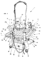
- the workbench for cutting metal elements by means of plasma torches T object of the invention comprises a bearing structure 2 in which it is possible to identify at least one work surface 3, on which said metal elements P to be processed are positioned and at least one support unit 4, 5 of said torch T suited to carry out said operations.
- the above mentioned support unit 4, 5 is associated with moving and guide means 6, 7 suited to move said torch T with respect to said work surface 3.
- the workbench 1 is provided with two distinct support units 4, 5 of the plasma torch T.
- the first support unit 4 comprises a torch holder 8 slidingly coupled with a first guide structure 9 that defines a first displacement axis X on a plane parallel to the work surface 3.
- the first guide structure 9 is supported at its ends by two vertical elements 10, 11, each one of which is connected to a corresponding linear guide structure 12, 13 associated with the bearing structure 2 of the workbench 1 that defines a second displacement axis Y perpendicular to the first axis X .
- the vertical elements may also be sized according to the user's needs.
- the result is a substantially door-shaped structure that slides along the work surface 3 of the bench 1 .
- the linear guides 12, 13 associated with the workbench 1, on which the described vertical elements 10, 11 slide, are provided with a graduated ruler 14, 15 and with first reference means 16, 17 to define the stroke of the plasma torch T along the axis Y.
- first guide structure 9, to which the torch holder 8 is associated is provided with a graduated ruler 18 and with second reference means 19, 20 to define the processing stroke of the torch T along the axis X.
- hooking means 21, 22, 23, 24 that make it possible to withdraw the entire first support unit 4 from the workbench 1 if this is not going to be used or represents an obstacle in the work area.
- the vertical elements 110, 111 are equipped with hinge means 101, 102 for connection to the guide structures 112, 113, allowing the whole support unit 104 to be rotated around the axis X' defined by the hinge means 101, 102.
- the rotation of the support unit 104 makes it possible to carry out cutting operations on inclined surfaces, as shown in Figure 8, and also to tilt the support unit 104 completely, as shown in Figure 9, to clear the work area 103 if it is necessary to cut large pieces using only the support unit 105.
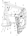
- the second support unit 5 comprises a support arm 25 protruding over the work surface 3 and having one end 25a connected to the bearing structure 2 of the workbench 1 through a vertical element 26, while on the opposite end 25b there are driving means 27 connected to a second torch holder 31 by means of a support rod 28 keyed to the shaft 29 of the electric motor 30.
- a pneumatic motor may be installed in the second support unit 5 instead of the electric motor.
- the torch holder 31 is associated with the support rod 28 through a guide structure 32 constituted by a rack 33, equipped with a graduated ruler 34, guided with an adjusting knob 35 suited to modify the distance between the torch holder 31 and the support rod 28 in order to vary the radius of the processed profile.
- the support rod 28 is also provided with a point 52 to center the piece P to be processed.
- the vertical element 26 that supports the arm 25 is associated with the workbench 1 by means of a linear guide 36 that allows it to be moved along the direction defined by the axis Y.
- the support arm 25 is connected to the vertical element 26 through moving means 38 suited to allow it to be rotated, in such a way as to enable the torch T to carry out the required operations in the different zones of the work surface 3.
- the workbench 1 is equipped with a control panel 39 used to control the described driving means 27 for the rotation of the torch holder 31, said panel being provided with push buttons 40 to control the rotary movement of the torch holder 31 and with a potentiometer 41 to adjust its rotation speed.
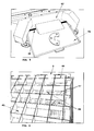
- bearing structure 2 of the workbench 1 comprises a box-type body 42 defining an internal space 43 for collecting processing scraps.
- the box-type body 42 has the shape of a truncated cone, in the upper part of which there is the work surface 3 constituted by a grid structure 44, while in its lower part there is a container 45 to collect said processing scraps.
- the collecting container 45 is also provided with a drawer 46 that allows the accumulated processing scraps to be thrown away.
- partitions 47 are provided, which are equipped with grids 48 defining an air space 49 for the suction of the fumes produced during the welding or plasma cutting operations.
- suction vents 50 that allow the workbench 1 to be connected to a centralized fume suction system.
- the workbench 1 is also provided with independent wheels 51 that allow it to be comfortably transported to the different areas of the workshop where it must be used.
- the first support unit 4 it is possible, by properly arranging the first 16, 17 and second 19, 20 reference means with the graduated ruler 14, 15, 18, to obtain polygonal profiles, like for example a rectangle, with the dimensions set by the user.
- the torch T is manually guided by the operator, who moves it by means of the guide structures 9, 12, 13 described above.
- the second support unit 5 is used, through which, once the plasma torch T has been positioned in the corresponding torch holder 31, it is possible to adjust the radius of the circumference and to carry out the operation automatically, by starting the above mentioned driving means 27 that allow the torch T to follow a circular profile whose radius is set by adjusting the rack guide 32.
- the invention also achieves the aim to implement a workbench that allows the above mentioned operations to be carried out with no need to subject the piece to further finishing operations.
Landscapes
- Physics & Mathematics (AREA)
- Optics & Photonics (AREA)
- Engineering & Computer Science (AREA)
- Mechanical Engineering (AREA)
- Arc Welding In General (AREA)
Applications Claiming Priority (2)
| Application Number | Priority Date | Filing Date | Title |
|---|---|---|---|
| ITVI20040025 | 2004-02-17 | ||
| ITVI20040025 ITVI20040025A1 (it) | 2004-02-17 | 2004-02-17 | Banco di lavoro per lavorazioni di taglio al plasma o saldatura |
Publications (2)
| Publication Number | Publication Date |
|---|---|
| EP1563944A2 true EP1563944A2 (de) | 2005-08-17 |
| EP1563944A3 EP1563944A3 (de) | 2005-12-28 |
Family
ID=34685661
Family Applications (1)
| Application Number | Title | Priority Date | Filing Date |
|---|---|---|---|
| EP05101166A Withdrawn EP1563944A3 (de) | 2004-02-17 | 2005-02-16 | Werkbank um Plasmaschneiden oder Schweissarbeiten |
Country Status (2)
| Country | Link |
|---|---|
| EP (1) | EP1563944A3 (de) |
| IT (1) | ITVI20040025A1 (de) |
Cited By (3)
| Publication number | Priority date | Publication date | Assignee | Title |
|---|---|---|---|---|
| AT511994A1 (de) * | 2011-09-29 | 2013-04-15 | Procon Gmbh Maschinen & Industrieanlagen | Schweissroboter-arbeitsplatz |
| CN106312425A (zh) * | 2016-10-28 | 2017-01-11 | 衡阳智源农业科技有限公司 | 一种多功能可旋转的升降式电焊台 |
| CN106378555A (zh) * | 2016-10-21 | 2017-02-08 | 宁夏天地奔牛实业集团有限公司 | 移动式上向反井钻机用稳定器堆焊辅助装置 |
Families Citing this family (1)
| Publication number | Priority date | Publication date | Assignee | Title |
|---|---|---|---|---|
| CN120461014B (zh) * | 2025-05-16 | 2025-10-10 | 广元明坤新材料科技有限公司 | 一种铝型材加工焊接装置 |
Family Cites Families (4)
| Publication number | Priority date | Publication date | Assignee | Title |
|---|---|---|---|---|
| US2688190A (en) * | 1950-05-06 | 1954-09-07 | Jerry R Hayes | Acetylene cutting torch compass |
| US3081990A (en) * | 1961-03-10 | 1963-03-19 | Donald A Fagan | Gas cutting machine |
| DE3527954A1 (de) * | 1985-08-03 | 1987-02-05 | Messer Griesheim Gmbh | Fuehrungsmaschine fuer brenner, insbesondere plasmaschneidbrenner |
| US6218639B1 (en) * | 1999-11-10 | 2001-04-17 | Jason Bulle | Plasma torch cutting system |
-
2004
- 2004-02-17 IT ITVI20040025 patent/ITVI20040025A1/it unknown
-
2005
- 2005-02-16 EP EP05101166A patent/EP1563944A3/de not_active Withdrawn
Cited By (4)
| Publication number | Priority date | Publication date | Assignee | Title |
|---|---|---|---|---|
| AT511994A1 (de) * | 2011-09-29 | 2013-04-15 | Procon Gmbh Maschinen & Industrieanlagen | Schweissroboter-arbeitsplatz |
| AT511994B1 (de) * | 2011-09-29 | 2013-06-15 | Procon Gmbh Maschinen & Industrieanlagen | Schweissroboter-arbeitsplatz |
| CN106378555A (zh) * | 2016-10-21 | 2017-02-08 | 宁夏天地奔牛实业集团有限公司 | 移动式上向反井钻机用稳定器堆焊辅助装置 |
| CN106312425A (zh) * | 2016-10-28 | 2017-01-11 | 衡阳智源农业科技有限公司 | 一种多功能可旋转的升降式电焊台 |
Also Published As
| Publication number | Publication date |
|---|---|
| EP1563944A3 (de) | 2005-12-28 |
| ITVI20040025A1 (it) | 2004-05-17 |
Similar Documents
| Publication | Publication Date | Title |
|---|---|---|
| US5700117A (en) | Machine tool for machining panels and plates | |
| EP0608746B1 (de) | CNC-gesteuerte Holzbearbeitungsanlage, insbesondere für lange Werkstücke wie Balken | |
| EP2983879B1 (de) | Mehrachsige werkzeugmaschine zum bearbeiten von steinplatten und/oder -blöcken | |
| US11267078B2 (en) | Laser cutting machine for the working of material, presented in sheet and/or reel form | |
| US5897275A (en) | Machine tool for machining panels and plates | |
| EP2145744A1 (de) | Vorrichtung und Verfahren zum Schneiden von Platten. | |
| EP2560786B1 (de) | Verfahren und vorrichtung zum schneiden von öffnungen in flache, konkave oder konvexe oberflächen | |
| EP0484674B1 (de) | Verfahren zum automatischen Bearbeiten der Ränder von Glasscheiben und Gerät zur Durchführung des Verfahrens | |
| CN107598368A (zh) | 激光切割机 | |
| CN116329684A (zh) | 放电金属丝机加工装置 | |
| EP3579985A1 (de) | Absaugtisch mit einem werkstückhalter für ein zu haltendes werkstück | |
| DE19800034A1 (de) | Werkzeugmaschine für Bearbeitungswerkzeuge aus der Gruppe Schleifkörper und Fräser mit mindestens einem Werkzeugträger | |
| DE19904860A1 (de) | Vertikaldrehmaschine | |
| US4288680A (en) | Apparatus for cutting mould notches for strip steel cutting tools | |
| EP1755824B1 (de) | Vertikaldrehmaschine mit zwei abwechselnd arbeitenden werkstückspindeln | |
| EP1974853A1 (de) | Vorrichtung zum Bearbeiten von Werkstücken | |
| CN112276649A (zh) | 一种车铣复合带刀塔数控机床 | |
| EP0419754B1 (de) | Schneidmaschine zum Schneiden von Flachmaterial | |
| EP0921916B1 (de) | Apparat zum maschinellen bearbeiten von vertikalen tafeln | |
| CN211564656U (zh) | 高效率高精度的切角机 | |
| EP3431240A1 (de) | Vorrichtung zum trennen von plattenmaterial | |
| JPS5816980B2 (ja) | 金属加工機械 | |
| US20190168352A1 (en) | Equipment for processing glass sheets | |
| CN214559778U (zh) | 全自动针刺磨削倒角研磨设备 | |
| DE10251515B3 (de) | Sägemaschine und Sägeverfahren |
Legal Events
| Date | Code | Title | Description |
|---|---|---|---|
| PUAI | Public reference made under article 153(3) epc to a published international application that has entered the european phase |
Free format text: ORIGINAL CODE: 0009012 |
|
| AK | Designated contracting states |
Kind code of ref document: A2 Designated state(s): AT BE BG CH CY CZ DE DK EE ES FI FR GB GR HU IE IS IT LI LT LU MC NL PL PT RO SE SI SK TR |
|
| AX | Request for extension of the european patent |
Extension state: AL BA HR LV MK YU |
|
| PUAL | Search report despatched |
Free format text: ORIGINAL CODE: 0009013 |
|
| AK | Designated contracting states |
Kind code of ref document: A3 Designated state(s): AT BE BG CH CY CZ DE DK EE ES FI FR GB GR HU IE IS IT LI LT LU MC NL PL PT RO SE SI SK TR |
|
| AX | Request for extension of the european patent |
Extension state: AL BA HR LV MK YU |
|
| AKX | Designation fees paid | ||
| REG | Reference to a national code |
Ref country code: DE Ref legal event code: 8566 |
|
| STAA | Information on the status of an ep patent application or granted ep patent |
Free format text: STATUS: THE APPLICATION IS DEEMED TO BE WITHDRAWN |
|
| 18D | Application deemed to be withdrawn |
Effective date: 20060629 |