EP1564055A2 - Commande d'un véhicule hybride lors du départ - Google Patents
Commande d'un véhicule hybride lors du départ Download PDFInfo
- Publication number
- EP1564055A2 EP1564055A2 EP05101130A EP05101130A EP1564055A2 EP 1564055 A2 EP1564055 A2 EP 1564055A2 EP 05101130 A EP05101130 A EP 05101130A EP 05101130 A EP05101130 A EP 05101130A EP 1564055 A2 EP1564055 A2 EP 1564055A2
- Authority
- EP
- European Patent Office
- Prior art keywords
- determining
- torque
- transmission
- speed
- input
- Prior art date
- Legal status (The legal status is an assumption and is not a legal conclusion. Google has not performed a legal analysis and makes no representation as to the accuracy of the status listed.)
- Withdrawn
Links
Images


Classifications
-
- B—PERFORMING OPERATIONS; TRANSPORTING
- B60—VEHICLES IN GENERAL
- B60W—CONJOINT CONTROL OF VEHICLE SUB-UNITS OF DIFFERENT TYPE OR DIFFERENT FUNCTION; CONTROL SYSTEMS SPECIALLY ADAPTED FOR HYBRID VEHICLES; ROAD VEHICLE DRIVE CONTROL SYSTEMS FOR PURPOSES NOT RELATED TO THE CONTROL OF A PARTICULAR SUB-UNIT
- B60W20/00—Control systems specially adapted for hybrid vehicles
-
- B—PERFORMING OPERATIONS; TRANSPORTING
- B60—VEHICLES IN GENERAL
- B60K—ARRANGEMENT OR MOUNTING OF PROPULSION UNITS OR OF TRANSMISSIONS IN VEHICLES; ARRANGEMENT OR MOUNTING OF PLURAL DIVERSE PRIME-MOVERS IN VEHICLES; AUXILIARY DRIVES FOR VEHICLES; INSTRUMENTATION OR DASHBOARDS FOR VEHICLES; ARRANGEMENTS IN CONNECTION WITH COOLING, AIR INTAKE, GAS EXHAUST OR FUEL SUPPLY OF PROPULSION UNITS IN VEHICLES
- B60K6/00—Arrangement or mounting of plural diverse prime-movers for mutual or common propulsion, e.g. hybrid propulsion systems comprising electric motors and internal combustion engines
- B60K6/20—Arrangement or mounting of plural diverse prime-movers for mutual or common propulsion, e.g. hybrid propulsion systems comprising electric motors and internal combustion engines the prime-movers consisting of electric motors and internal combustion engines, e.g. HEVs
- B60K6/22—Arrangement or mounting of plural diverse prime-movers for mutual or common propulsion, e.g. hybrid propulsion systems comprising electric motors and internal combustion engines the prime-movers consisting of electric motors and internal combustion engines, e.g. HEVs characterised by apparatus, components or means specially adapted for HEVs
- B60K6/36—Arrangement or mounting of plural diverse prime-movers for mutual or common propulsion, e.g. hybrid propulsion systems comprising electric motors and internal combustion engines the prime-movers consisting of electric motors and internal combustion engines, e.g. HEVs characterised by apparatus, components or means specially adapted for HEVs characterised by the transmission gearings
- B60K6/365—Arrangement or mounting of plural diverse prime-movers for mutual or common propulsion, e.g. hybrid propulsion systems comprising electric motors and internal combustion engines the prime-movers consisting of electric motors and internal combustion engines, e.g. HEVs characterised by apparatus, components or means specially adapted for HEVs characterised by the transmission gearings with the gears having orbital motion
-
- B—PERFORMING OPERATIONS; TRANSPORTING
- B60—VEHICLES IN GENERAL
- B60K—ARRANGEMENT OR MOUNTING OF PROPULSION UNITS OR OF TRANSMISSIONS IN VEHICLES; ARRANGEMENT OR MOUNTING OF PLURAL DIVERSE PRIME-MOVERS IN VEHICLES; AUXILIARY DRIVES FOR VEHICLES; INSTRUMENTATION OR DASHBOARDS FOR VEHICLES; ARRANGEMENTS IN CONNECTION WITH COOLING, AIR INTAKE, GAS EXHAUST OR FUEL SUPPLY OF PROPULSION UNITS IN VEHICLES
- B60K6/00—Arrangement or mounting of plural diverse prime-movers for mutual or common propulsion, e.g. hybrid propulsion systems comprising electric motors and internal combustion engines
- B60K6/20—Arrangement or mounting of plural diverse prime-movers for mutual or common propulsion, e.g. hybrid propulsion systems comprising electric motors and internal combustion engines the prime-movers consisting of electric motors and internal combustion engines, e.g. HEVs
- B60K6/22—Arrangement or mounting of plural diverse prime-movers for mutual or common propulsion, e.g. hybrid propulsion systems comprising electric motors and internal combustion engines the prime-movers consisting of electric motors and internal combustion engines, e.g. HEVs characterised by apparatus, components or means specially adapted for HEVs
- B60K6/38—Arrangement or mounting of plural diverse prime-movers for mutual or common propulsion, e.g. hybrid propulsion systems comprising electric motors and internal combustion engines the prime-movers consisting of electric motors and internal combustion engines, e.g. HEVs characterised by apparatus, components or means specially adapted for HEVs characterised by the driveline clutches
- B60K6/387—Actuated clutches, i.e. clutches engaged or disengaged by electric, hydraulic or mechanical actuating means
-
- B—PERFORMING OPERATIONS; TRANSPORTING
- B60—VEHICLES IN GENERAL
- B60K—ARRANGEMENT OR MOUNTING OF PROPULSION UNITS OR OF TRANSMISSIONS IN VEHICLES; ARRANGEMENT OR MOUNTING OF PLURAL DIVERSE PRIME-MOVERS IN VEHICLES; AUXILIARY DRIVES FOR VEHICLES; INSTRUMENTATION OR DASHBOARDS FOR VEHICLES; ARRANGEMENTS IN CONNECTION WITH COOLING, AIR INTAKE, GAS EXHAUST OR FUEL SUPPLY OF PROPULSION UNITS IN VEHICLES
- B60K6/00—Arrangement or mounting of plural diverse prime-movers for mutual or common propulsion, e.g. hybrid propulsion systems comprising electric motors and internal combustion engines
- B60K6/20—Arrangement or mounting of plural diverse prime-movers for mutual or common propulsion, e.g. hybrid propulsion systems comprising electric motors and internal combustion engines the prime-movers consisting of electric motors and internal combustion engines, e.g. HEVs
- B60K6/22—Arrangement or mounting of plural diverse prime-movers for mutual or common propulsion, e.g. hybrid propulsion systems comprising electric motors and internal combustion engines the prime-movers consisting of electric motors and internal combustion engines, e.g. HEVs characterised by apparatus, components or means specially adapted for HEVs
- B60K6/40—Arrangement or mounting of plural diverse prime-movers for mutual or common propulsion, e.g. hybrid propulsion systems comprising electric motors and internal combustion engines the prime-movers consisting of electric motors and internal combustion engines, e.g. HEVs characterised by apparatus, components or means specially adapted for HEVs characterised by the assembly or relative disposition of components
-
- B—PERFORMING OPERATIONS; TRANSPORTING
- B60—VEHICLES IN GENERAL
- B60K—ARRANGEMENT OR MOUNTING OF PROPULSION UNITS OR OF TRANSMISSIONS IN VEHICLES; ARRANGEMENT OR MOUNTING OF PLURAL DIVERSE PRIME-MOVERS IN VEHICLES; AUXILIARY DRIVES FOR VEHICLES; INSTRUMENTATION OR DASHBOARDS FOR VEHICLES; ARRANGEMENTS IN CONNECTION WITH COOLING, AIR INTAKE, GAS EXHAUST OR FUEL SUPPLY OF PROPULSION UNITS IN VEHICLES
- B60K6/00—Arrangement or mounting of plural diverse prime-movers for mutual or common propulsion, e.g. hybrid propulsion systems comprising electric motors and internal combustion engines
- B60K6/20—Arrangement or mounting of plural diverse prime-movers for mutual or common propulsion, e.g. hybrid propulsion systems comprising electric motors and internal combustion engines the prime-movers consisting of electric motors and internal combustion engines, e.g. HEVs
- B60K6/42—Arrangement or mounting of plural diverse prime-movers for mutual or common propulsion, e.g. hybrid propulsion systems comprising electric motors and internal combustion engines the prime-movers consisting of electric motors and internal combustion engines, e.g. HEVs characterised by the architecture of the hybrid electric vehicle
- B60K6/48—Parallel type
-
- B—PERFORMING OPERATIONS; TRANSPORTING
- B60—VEHICLES IN GENERAL
- B60K—ARRANGEMENT OR MOUNTING OF PROPULSION UNITS OR OF TRANSMISSIONS IN VEHICLES; ARRANGEMENT OR MOUNTING OF PLURAL DIVERSE PRIME-MOVERS IN VEHICLES; AUXILIARY DRIVES FOR VEHICLES; INSTRUMENTATION OR DASHBOARDS FOR VEHICLES; ARRANGEMENTS IN CONNECTION WITH COOLING, AIR INTAKE, GAS EXHAUST OR FUEL SUPPLY OF PROPULSION UNITS IN VEHICLES
- B60K6/00—Arrangement or mounting of plural diverse prime-movers for mutual or common propulsion, e.g. hybrid propulsion systems comprising electric motors and internal combustion engines
- B60K6/20—Arrangement or mounting of plural diverse prime-movers for mutual or common propulsion, e.g. hybrid propulsion systems comprising electric motors and internal combustion engines the prime-movers consisting of electric motors and internal combustion engines, e.g. HEVs
- B60K6/50—Architecture of the driveline characterised by arrangement or kind of transmission units
- B60K6/54—Transmission for changing ratio
- B60K6/547—Transmission for changing ratio the transmission being a stepped gearing
-
- B—PERFORMING OPERATIONS; TRANSPORTING
- B60—VEHICLES IN GENERAL
- B60W—CONJOINT CONTROL OF VEHICLE SUB-UNITS OF DIFFERENT TYPE OR DIFFERENT FUNCTION; CONTROL SYSTEMS SPECIALLY ADAPTED FOR HYBRID VEHICLES; ROAD VEHICLE DRIVE CONTROL SYSTEMS FOR PURPOSES NOT RELATED TO THE CONTROL OF A PARTICULAR SUB-UNIT
- B60W10/00—Conjoint control of vehicle sub-units of different type or different function
- B60W10/02—Conjoint control of vehicle sub-units of different type or different function including control of driveline clutches
-
- B—PERFORMING OPERATIONS; TRANSPORTING
- B60—VEHICLES IN GENERAL
- B60W—CONJOINT CONTROL OF VEHICLE SUB-UNITS OF DIFFERENT TYPE OR DIFFERENT FUNCTION; CONTROL SYSTEMS SPECIALLY ADAPTED FOR HYBRID VEHICLES; ROAD VEHICLE DRIVE CONTROL SYSTEMS FOR PURPOSES NOT RELATED TO THE CONTROL OF A PARTICULAR SUB-UNIT
- B60W10/00—Conjoint control of vehicle sub-units of different type or different function
- B60W10/04—Conjoint control of vehicle sub-units of different type or different function including control of propulsion units
- B60W10/06—Conjoint control of vehicle sub-units of different type or different function including control of propulsion units including control of combustion engines
-
- B—PERFORMING OPERATIONS; TRANSPORTING
- B60—VEHICLES IN GENERAL
- B60W—CONJOINT CONTROL OF VEHICLE SUB-UNITS OF DIFFERENT TYPE OR DIFFERENT FUNCTION; CONTROL SYSTEMS SPECIALLY ADAPTED FOR HYBRID VEHICLES; ROAD VEHICLE DRIVE CONTROL SYSTEMS FOR PURPOSES NOT RELATED TO THE CONTROL OF A PARTICULAR SUB-UNIT
- B60W10/00—Conjoint control of vehicle sub-units of different type or different function
- B60W10/04—Conjoint control of vehicle sub-units of different type or different function including control of propulsion units
- B60W10/08—Conjoint control of vehicle sub-units of different type or different function including control of propulsion units including control of electric propulsion units, e.g. motors or generators
-
- B—PERFORMING OPERATIONS; TRANSPORTING
- B60—VEHICLES IN GENERAL
- B60W—CONJOINT CONTROL OF VEHICLE SUB-UNITS OF DIFFERENT TYPE OR DIFFERENT FUNCTION; CONTROL SYSTEMS SPECIALLY ADAPTED FOR HYBRID VEHICLES; ROAD VEHICLE DRIVE CONTROL SYSTEMS FOR PURPOSES NOT RELATED TO THE CONTROL OF A PARTICULAR SUB-UNIT
- B60W30/00—Purposes of road vehicle drive control systems not related to the control of a particular sub-unit, e.g. of systems using conjoint control of vehicle sub-units
- B60W30/18—Propelling the vehicle
- B60W30/18009—Propelling the vehicle related to particular drive situations
- B60W30/18027—Drive off, accelerating from standstill
-
- B—PERFORMING OPERATIONS; TRANSPORTING
- B60—VEHICLES IN GENERAL
- B60L—PROPULSION OF ELECTRICALLY-PROPELLED VEHICLES; SUPPLYING ELECTRIC POWER FOR AUXILIARY EQUIPMENT OF ELECTRICALLY-PROPELLED VEHICLES; ELECTRODYNAMIC BRAKE SYSTEMS FOR VEHICLES IN GENERAL; MAGNETIC SUSPENSION OR LEVITATION FOR VEHICLES; MONITORING OPERATING VARIABLES OF ELECTRICALLY-PROPELLED VEHICLES; ELECTRIC SAFETY DEVICES FOR ELECTRICALLY-PROPELLED VEHICLES
- B60L2240/00—Control parameters of input or output; Target parameters
- B60L2240/40—Drive Train control parameters
- B60L2240/42—Drive Train control parameters related to electric machines
- B60L2240/423—Torque
-
- B—PERFORMING OPERATIONS; TRANSPORTING
- B60—VEHICLES IN GENERAL
- B60L—PROPULSION OF ELECTRICALLY-PROPELLED VEHICLES; SUPPLYING ELECTRIC POWER FOR AUXILIARY EQUIPMENT OF ELECTRICALLY-PROPELLED VEHICLES; ELECTRODYNAMIC BRAKE SYSTEMS FOR VEHICLES IN GENERAL; MAGNETIC SUSPENSION OR LEVITATION FOR VEHICLES; MONITORING OPERATING VARIABLES OF ELECTRICALLY-PROPELLED VEHICLES; ELECTRIC SAFETY DEVICES FOR ELECTRICALLY-PROPELLED VEHICLES
- B60L2240/00—Control parameters of input or output; Target parameters
- B60L2240/40—Drive Train control parameters
- B60L2240/48—Drive Train control parameters related to transmissions
- B60L2240/486—Operating parameters
-
- B—PERFORMING OPERATIONS; TRANSPORTING
- B60—VEHICLES IN GENERAL
- B60W—CONJOINT CONTROL OF VEHICLE SUB-UNITS OF DIFFERENT TYPE OR DIFFERENT FUNCTION; CONTROL SYSTEMS SPECIALLY ADAPTED FOR HYBRID VEHICLES; ROAD VEHICLE DRIVE CONTROL SYSTEMS FOR PURPOSES NOT RELATED TO THE CONTROL OF A PARTICULAR SUB-UNIT
- B60W50/00—Details of control systems for road vehicle drive control not related to the control of a particular sub-unit, e.g. process diagnostic or vehicle driver interfaces
- B60W2050/0001—Details of the control system
- B60W2050/0002—Automatic control, details of type of controller or control system architecture
- B60W2050/0008—Feedback, closed loop systems or details of feedback error signal
- B60W2050/0011—Proportional Integral Differential [PID] controller
-
- B—PERFORMING OPERATIONS; TRANSPORTING
- B60—VEHICLES IN GENERAL
- B60W—CONJOINT CONTROL OF VEHICLE SUB-UNITS OF DIFFERENT TYPE OR DIFFERENT FUNCTION; CONTROL SYSTEMS SPECIALLY ADAPTED FOR HYBRID VEHICLES; ROAD VEHICLE DRIVE CONTROL SYSTEMS FOR PURPOSES NOT RELATED TO THE CONTROL OF A PARTICULAR SUB-UNIT
- B60W2510/00—Input parameters relating to a particular sub-units
- B60W2510/06—Combustion engines, Gas turbines
- B60W2510/0604—Throttle position
-
- B—PERFORMING OPERATIONS; TRANSPORTING
- B60—VEHICLES IN GENERAL
- B60W—CONJOINT CONTROL OF VEHICLE SUB-UNITS OF DIFFERENT TYPE OR DIFFERENT FUNCTION; CONTROL SYSTEMS SPECIALLY ADAPTED FOR HYBRID VEHICLES; ROAD VEHICLE DRIVE CONTROL SYSTEMS FOR PURPOSES NOT RELATED TO THE CONTROL OF A PARTICULAR SUB-UNIT
- B60W2510/00—Input parameters relating to a particular sub-units
- B60W2510/10—Change speed gearings
- B60W2510/1015—Input shaft speed, e.g. turbine speed
-
- B—PERFORMING OPERATIONS; TRANSPORTING
- B60—VEHICLES IN GENERAL
- B60W—CONJOINT CONTROL OF VEHICLE SUB-UNITS OF DIFFERENT TYPE OR DIFFERENT FUNCTION; CONTROL SYSTEMS SPECIALLY ADAPTED FOR HYBRID VEHICLES; ROAD VEHICLE DRIVE CONTROL SYSTEMS FOR PURPOSES NOT RELATED TO THE CONTROL OF A PARTICULAR SUB-UNIT
- B60W2520/00—Input parameters relating to overall vehicle dynamics
- B60W2520/10—Longitudinal speed
-
- B—PERFORMING OPERATIONS; TRANSPORTING
- B60—VEHICLES IN GENERAL
- B60W—CONJOINT CONTROL OF VEHICLE SUB-UNITS OF DIFFERENT TYPE OR DIFFERENT FUNCTION; CONTROL SYSTEMS SPECIALLY ADAPTED FOR HYBRID VEHICLES; ROAD VEHICLE DRIVE CONTROL SYSTEMS FOR PURPOSES NOT RELATED TO THE CONTROL OF A PARTICULAR SUB-UNIT
- B60W2540/00—Input parameters relating to occupants
- B60W2540/16—Ratio selector position
-
- B—PERFORMING OPERATIONS; TRANSPORTING
- B60—VEHICLES IN GENERAL
- B60W—CONJOINT CONTROL OF VEHICLE SUB-UNITS OF DIFFERENT TYPE OR DIFFERENT FUNCTION; CONTROL SYSTEMS SPECIALLY ADAPTED FOR HYBRID VEHICLES; ROAD VEHICLE DRIVE CONTROL SYSTEMS FOR PURPOSES NOT RELATED TO THE CONTROL OF A PARTICULAR SUB-UNIT
- B60W2710/00—Output or target parameters relating to a particular sub-units
- B60W2710/08—Electric propulsion units
- B60W2710/083—Torque
-
- B—PERFORMING OPERATIONS; TRANSPORTING
- B60—VEHICLES IN GENERAL
- B60W—CONJOINT CONTROL OF VEHICLE SUB-UNITS OF DIFFERENT TYPE OR DIFFERENT FUNCTION; CONTROL SYSTEMS SPECIALLY ADAPTED FOR HYBRID VEHICLES; ROAD VEHICLE DRIVE CONTROL SYSTEMS FOR PURPOSES NOT RELATED TO THE CONTROL OF A PARTICULAR SUB-UNIT
- B60W2710/00—Output or target parameters relating to a particular sub-units
- B60W2710/10—Change speed gearings
- B60W2710/1011—Input shaft speed, e.g. turbine speed
-
- F—MECHANICAL ENGINEERING; LIGHTING; HEATING; WEAPONS; BLASTING
- F16—ENGINEERING ELEMENTS AND UNITS; GENERAL MEASURES FOR PRODUCING AND MAINTAINING EFFECTIVE FUNCTIONING OF MACHINES OR INSTALLATIONS; THERMAL INSULATION IN GENERAL
- F16H—GEARING
- F16H2312/00—Driving activities
- F16H2312/02—Driving off
-
- Y—GENERAL TAGGING OF NEW TECHNOLOGICAL DEVELOPMENTS; GENERAL TAGGING OF CROSS-SECTIONAL TECHNOLOGIES SPANNING OVER SEVERAL SECTIONS OF THE IPC; TECHNICAL SUBJECTS COVERED BY FORMER USPC CROSS-REFERENCE ART COLLECTIONS [XRACs] AND DIGESTS
- Y02—TECHNOLOGIES OR APPLICATIONS FOR MITIGATION OR ADAPTATION AGAINST CLIMATE CHANGE
- Y02T—CLIMATE CHANGE MITIGATION TECHNOLOGIES RELATED TO TRANSPORTATION
- Y02T10/00—Road transport of goods or passengers
- Y02T10/60—Other road transportation technologies with climate change mitigation effect
- Y02T10/62—Hybrid vehicles
-
- Y—GENERAL TAGGING OF NEW TECHNOLOGICAL DEVELOPMENTS; GENERAL TAGGING OF CROSS-SECTIONAL TECHNOLOGIES SPANNING OVER SEVERAL SECTIONS OF THE IPC; TECHNICAL SUBJECTS COVERED BY FORMER USPC CROSS-REFERENCE ART COLLECTIONS [XRACs] AND DIGESTS
- Y02—TECHNOLOGIES OR APPLICATIONS FOR MITIGATION OR ADAPTATION AGAINST CLIMATE CHANGE
- Y02T—CLIMATE CHANGE MITIGATION TECHNOLOGIES RELATED TO TRANSPORTATION
- Y02T10/00—Road transport of goods or passengers
- Y02T10/60—Other road transportation technologies with climate change mitigation effect
- Y02T10/64—Electric machine technologies in electromobility
Definitions
- the invention relates to hybrid vehicle powertrains in which an electric motor and an internal combustion engine provide power to a transmission having no torque converter.
- a hydrokinetic torque converter is conventionally located between the engine shaft and transmission input, the torque converter increasing engine torque during launch to provides a powerful launch feel to the driver during acceleration from a stop.
- the impeller of the torque converter receives engine torque and the turbine of the torque converter transfers torque to the torque input element of multiple-ratio gearing of the transmission.
- the presence of the torque converter in the torque flow path introduces hydrokinetic power losses, particularly during startup of the vehicle, as the torque converter fluid in the converter torus circuit is accelerated and decelerated. These losses are manifested in heat loss to the hydrokinetic fluid, which requires a heat exchanger to maintain an acceptable hydrokinetic fluid temperature.
- An electric torque converterless transmission has been designed to address drivability concerns while minimizing losses. That transmission uses a base power-shifting transmission with standard gear ratios, removes the torque converter, and places a high voltage motor on the transmission input. Without the torque converter, the launch for the transmission is accomplished by actively controlling the existing planetary clutches and the electric motor. A control system for coordinating the clutch and motor to provide acceptable launch feel is required.
- the method further comprising the steps of determining a current vehicle speed; determining a performance adder based on the current vehicle speed, and combining the performance adder with the target input speed before using the variable pressure to control the torque capacity of the input clutch.
- An an indication that a vehicle launch condition has been initiated may be produced by comparing the current input speed and the target input speed; and producing the indication when target input speed exceeds the current input speed.
- the invention provides a system as set forth in Claim 9 and a method as set forth in Claim 10 of the appended claims.
- the invention seeks to provide an improved hybrid electric vehicle transmission and control system that permits the internal combustion engine to be deactivated when the vehicle is at rest.
- the improved driveline includes an induction motor that is useful to provide added launch performance, and which permits the multiple-ratio transmission to operate throughout a desired ratio range without the need for using a hydrokinetic torque converter between the engine and the transmission input.
- the invention is particularly adapted for use with a hybrid electric vehicle including an internal combustion engine and a multiple-ratio transmission wherein provision is made for significantly improving fuel economy and reducing exhaust gas emissions.
- An input clutch also disconnects the engine from the torque path when the engine is required to operate at low throttle and during operation of the vehicle at low speed when only the induction motor is used to power the vehicle. It is at this time that the internal combustion engine is most inefficient. Thus, by disconnecting the engine, the engine may be reserved for operation in the speed range at which it is most efficient as the induction motor supplies the driving torque.
- the clutch may be used also to rapidly restart the engine when the vehicle is moving by using the vehicle momentum since the engine is connected mechanically through the clutch to the transmission input.
- the torque output of the induction motor can be optimized by maintaining the engine speed at a lower level than that which would be the case with a conventional automatic transmission having a torque converter.
- the launch performance is improved compared to a driveline with a conventional transmission because the output torque increases more rapidly during launch of the vehicle when the electric motor is used for launch purposes.
- a gasoline-electric hybrid vehicle driveline that includes an internal combustion engine 10, a multiple-ratio vehicle transmission 12, an induction motor 14 located in a drive path between the engine and transmission 12, and a friction clutch 16 located between the engine and the motor for driveably connecting and disconnect the engine and transmission.
- the rotor of the induction motor is connected directly to the torque input element of the multiple-ratio synchronous transmission. It is connected also to the engine crankshaft 10 through the friction clutch 16.
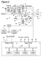
- FIG. 2 is a schematic representation of the gearing and control elements for the transmission of FIG. 1.
- the input shaft of the transmission is connected to the torque input side of the clutch 16.
- the electric motor is arranged so that it transmits torque in parallel relationship with respect to the engine torque input.
- the direct clutch (DC) shown at 20 connects transmission input shaft 22 to the ring gear 24 of a first simple planetary gear unit.
- Sun gear 26 of the simple planetary gear unit is connected through a forward clutch (FC) shown at 28 to the shaft 22.
- Ring gear 24 is connected to sun gear 30 of a second planetary gear unit.
- the ring gear 32 of the second planetary gear unit is connected to the planetary carrier 34 of the first planetary gear unit.
- the planetary carrier 36 for the second planetary gear unit is braked selectively by low-and-reverse brake (L/R) 38.
- Transmission input shaft 22 is connected through reverse clutch (RC) 40 to the sun gear 30 and is engaged during the first ratio drive operation.
- FIG. 3 is a chart, which illustrates the state of the clutches and brakes of the transmission 12 for each of the gear ratios.
- First gear is achieved by engaging the forward clutch and the low-and-reverse brake.
- Second forward drive ratio is achieved by engaging the forward clutch and the 2/4 band brake.
- Direct drive or third drive ratio is achieved by simultaneously engaging the forward clutch and the direct clutch, and fourth ratio or overdrive ratio is achieved by engaging the direct clutch and the 2/4 band brake.
- Reverse clutch 40 and low-and-reverse brake 38 are engaged during reverse drive operation.
- the ring gear 32 acts as a torque output element for the gearing. It defines a sprocket wheel 42, which drives a sprocket wheel 44 by means of a drive chain 46 engaged with both sprocket wheels. Sprocket wheel 44 drives the sun gear 48 of the final drive gear unit.
- the ring gear 50 of the final drive gear unit is anchored, and the planetary carrier 52 brings torque output to differential gearing 54, which transfers driving torque to each of two axle half shafts 56 and 58.
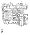
- FIG. 4 is a detailed cross sectional view of the electric induction motor 14, a starter/alternator, engine crankshaft 18, and transmission input shaft 22.
- the induction motor 14 includes a rotor 60 supported on a rotor hub 61, which is supported by needle bearing 62, 64 on a sleeve shaft 66, surrounding the transmission input shaft 22.
- the rotor 60 and rotor hub 61 are continually driveably connected to input shaft 22 by a spline connection 68.
- a motor stator 70 Surrounding rotor 60 is a motor stator 70, which includes stator windings 72, the stator and winding being fixed to a casing against rotation.
- a second torque delivery path connects the engine shaft 18 and input shaft 22, and is arranged in parallel with the path from the motor 14 to input shaft 22.
- the second path includes a torsion damper 74, connected by bolts 75, 76 to the engine shaft.
- the damper 74 is connected by a spline 78 to a disc 80, on which the input or start-up clutch 16 is supported.
- clutch 16 disengaged, the engine 10 is disconnected from the input shaft 22, and the induction motor is the only source of positive torque for the transmission 12.
- the clutch 16 disengaged during vehicle launch at low-throttle operating conditions when the induction motor is capable of providing sufficient torque to propel the vehicle.
- the engine which may be inoperative during low-speed operation, can be rapidly restarted merely by engaging the clutch 16 and actuating the engine ignition system.
- the input clutch 16 includes a set of friction discs 82, splined to the radially outer surface of disc 80. Interleaved with discs 82 are spacer plates 84, splined to the radially inner surface of rotor hub 61, and a blocker ring, secured to hub 61 by a snap ring 84 to limit axial displacement of the blocker ring and of the friction discs and spacer plates. Clutch 16 is controlled by a servo 88, which includes a hydraulic cylinder 90, a sealed piston 92 located in the cylinder, a Belleville return spring 94, and balance dam 96. The cylinder is pressurized and vented through passage 98.
- the control strategy of this invention can be applied to a powertrain in which clutch 16 is deleted, and the forward clutch 28 and low-and-reverse brake 38 are controlled instead according to this invention during vehicle launch conditions.
- vehicle launch is controlled through operation of the forward clutch 28 during vehicle forward launch and of the low-and-reverse brake 38 during vehicle reverse launch, in the same manner as will be described with reference to clutch 16.
- the torque converter of the transmission is eliminated, and the induction motor improves launch performance in the absence of the torque converter.
- a controller 100 receives signals generated by sensors, processes, and uses the input signals to determine the magnitude of pressure to be applied to clutch 16 in accordance with a clutch control strategy. Based upon this determination, the controller generates a command signal that causes the torque capacity of the clutch 16 to change, whereby the clutch slips, fully engages or fully disengages. The magnitude of clutch pressure establishes the magnitude of torque transmitted by the clutch 16. The controller also determines and command the magnitude of torque to be produced by the motor 12 by controlling the magnitude of current to by applied to the field windings of the motor.
- the controller 100 is a powertrain controller that includes one or more digital microprocessors or digital computers, which cooperatively perform calculations, and execute subroutines and control algorithms. Controller 100 preferably generates a pulse width modulated (PWM) command or output signal, which controls the amount of slippage between the friction discs and spacer plates of clutch 16, thereby controlling the relative magnitudes of torque and power transmitted through the clutch from the engine shaft 18 to the transmission input shaft 22.
- PWM pulse width modulated
- the duty cycle of the PWM signal is the percentage of the cycle time for which the signal is activated or enabled.
- the output signal of the controller is communicated to a solenoid 122, which operates a valve 124 that opens and closes a source of fluid pressure 126 to the servo 88 of clutch 16.
- the clutch duty cycle is interchangeably referred to as a pressure command, or clutch command.
- Controller 100 is preferably a microprocessor-based controller, which provides integrated control of engine 10 and transmission 12.
- Controller 100 includes a microprocessor MPU in communication with input ports, output ports, and computer readable media via a data/control bus 102.
- Computer readable media may include various types of volatile and nonvolatile memory such as random access memory (RAM), read-only memory (ROM), and keep-alive memory (KAM). These functional descriptions of the various types of volatile and nonvolatile storage may be implemented by any of a number of known physical devices including, but not limited to EPROMs, EEPROMs, PROMS, flash memory, and the like.
- Computer readable media include stored data representing instructions or algorithms executable by microprocessor MPU to implement the method for controlling input hydraulic pressure and motor torque according to the present invention.
- Vehicle launch is commanded when the driver steps on the accelerator pedal and the vehicle is at rest or at a low speed.
- the pressure command to the input clutch 16 is the output of a closed loop controller 100, which controls the transmission input speed through an incremental PID controller.
- the set point for the controller 100 is a function of actual throttle position (TP_raw) and vehicle speed (VS).
- the launch controller also controls the magnitude of torque produced by the electric motor 14, a starter/alternator.
- the torque produced by motor 14 provides extra boost to the engine torque, and aids in vehicle launch feel and acceleration so that the launch is comparable to today's torque converter-equipped vehicles.
- a torque converter's boost is limited to low speed, up to about 10 mph.
- the motor 14 can produce torque at relatively high motor speed and vehicle speed, as shown in Fig. 6. This torque producing ability improves launch performance time and feel by permitting boost to continue after the input clutch 16 is fully engaged and during operation in second gear.
- the launch controller There are two primary functions of the launch controller. One is to control the input clutch 16 such that it provides smooth torque delivery path to the wheels, while maintaining input speed. A second function of the controller is to control the output torque produced by the motor 14.
- the control strategy of this invention applies to a mechanical throttle, i.e., an engine control system in which a fixed relationship exists between the extent to which the accelerator pedal is depressed and the degree to which the engine throttle is open.
- the control strategy of this invention applies also to an electronic throttle control system, in which a sensor produces as input to a controller a signal representing the position of the accelerator pedal. The controller processes the signal and its variations with time to interpret the vehicle operator's desire for changes in engine and powertrain operation.
- Fig. 6 The time based implementation of the control strategy that produces the pressure command (prs_oncoming) to the solenoid 122 that controls clutch 16 is illustrated in Fig. 6.
- slo_rmp is a function of filtered throttle position (TP_flt), motor state (SA_state), and the state of the air conditioner (AC_state).
- TP_flt filtered throttle position
- SA_state motor state
- AC_state state of the air conditioner
- Ne_des_raw The desired engine speed, Ne_des_raw, 134 is set based on a function of throttle position. When the actual engine speed 136 exceeds the desired engine speed 134, the closed loop pressure controller is enabled at 138. If the engine speed (N1) is coming up normally, Ne_des is equal Ne_des_raw at the entry into closed loop. In case an unusual event, such as a neutral slam, causes the engine speed (N2) to be above Ne_des_raw, then Ne_des is filtered down to Ne_des_raw.
- sft_mode 5 is entered at 146, which causes an open loop parabolic increase 148 of commanded clutch pressure used to complete an upshift from first gear to second gear. After the clutch pressure is increased to its maximum magnitude, the pressure control is complete at 150, the sft_mode is set to 9 and the shift is completed.
- Boost time 146 is a parameter that is used to control the length of time that the motor 14 adds torque.
- boost time is set to be sufficient to allow full boost during operation in first gear and second gear.
- the boost timer will expire.
- the motor stops adding boost to minimize thermal durability issues and to allow charging of the battery.
- the boost timer is also used to improve drivability. It is not desirable to boost after a downshift from third gear to second gear. This condition is avoided by setting the boost time.
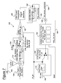
- the launch controller is illustrated schematically in Fig. 7. Two controllers are used: a closed loop pressure controller and an open loop motor torque controller.
- the input parameters are throttle position (TP_raw) 160, vehicle speed (VS) 162 and transmission input speed (Ni_flt) 164.
- the output 166 is the pressure command (prs_oncoming) to the input clutch 16.
- a target input speed is determined from a lookup table 168, which is a function of current filtered throttle position TP_flt, the output from a first order filter 170, whose input is TP_raw.
- the target input speed is target is added at a summing junction 172 to a factor of VS multiplied at 174 by the gain Knov to provide a target input speed that allows the engine speed to increase as the vehicle accelerates to provide a more natural experience for the driver.
- Target input speed is then filtered through a low-pass first order filter 176 to determine Ne_desired.
- the input speed should always be greater than the target input speed because the controller attempts to keep the input speed down by controlling the load on the engine/motor.
- a switch 178 sets the feedback to the filter 176 and an input to the summing junction 180 to Ni_flt instead of Ne_desired whenever the actual speed Ni_flt is lower than the target input speed Ne_desired.
- Ni_flt is subtracted from Ne_desired to obtain the error at summing junction 180.
- This error is then multiplied at 182 by the gain Kc.
- Kc is a proportional function of TP_flt because it is necessary to have higher gains at higher speeds.
- the output of this gain 182 is multiplied by an incremental Proportional + Integral + Derivative controller 184.
- the proportional term is dominant since steady state error is not critical to driveline smoothness, but maintaining very tight control on speed can cause transients in the pressure of clutch 16 pressure, which can be felt by the driver and passengers.
- the output of the PID controller is rate limited at 186 in the up direction to limit the rate of increase in the pressure of clutch 16.
- the controller issues a pressure command 166 to the solenoid 122, and the state of engagement or torque transmitting capacity of clutch 16 changes in response to that command.
- calibration tables 190 are used to determine the desired torque magnitude produced by motor or starter/alternator 14. These tables are a function of throttle position, and there is a table for each of the forward gears.
- the controller determines the current gear from signals produced by sensors whose output represents the speed of the input shaft 22 and the transmission output 56, 58.
- switch 192 sets TP_raw directly as an index to tables 190 to provide a fast response to the demand.
- switch 192 sets TP_flt as the index to tables 190.
- SA_torque_command The commanded magnitude of motor torque, SA_torque_command, 194 is highest in first gear, and lower in second gear. It is calibrated so that boost is not increased in third gear and fourth gear, although it is possible to add boost in those gears also.
- TRQ_SA_Mult 198 The output of the tables 190 is multiplied at 196 by TRQ_SA_Mult 198 to produce the motor commanded torque, SA_torque_command.
- the multiplier TRQ_SA_Mult graphically shown in Fig. 8, is used to turn the motor off prior to a gear ratio change.
- TRQ_SA_MULT is equal to 1.0 until vehicle speed reaches VS_END1, which occurs in sufficient time before the 1-2 gear shift at launch to assure that the commanded motor torque is zero when the gear shift begins.
- the length of the period during which TRQ_SA_MULT ramps down from 1.0 to zero is in the range 0.5-1.0 seconds.
- TRQ_SA_MULT is ramped back to 1.0. The same technique is used before the 2-3 upshift from second gear to third gear.
- the motor 14 is a multi-pole synchronous induction motor.
- the rotor is of the laminated squirrel cage type.
- the output torque is controlled by the magnitude of current applied to the field windings.
- the commanded output torque signal, SA_torque_command, produced by the controller changes the magnitude of current applied to the field windings in response to the command to produce the commanded output torque.
- the launch begins at time equal to 4.5 seconds.
- Some engine flare is allowed during this time. This flare keeps the engine speed 204 above the desired speed 206 in order to provide extra inertia torque when the engine speed is pulled down.
- This feature of the control produces a wheel torque 208 having a shape similar to that produced by a torque converter.
- the PID controller is tuned to keep the engine speed smooth by allowing the offset error rather than forcing a sudden change that holds tight speed control.
- Boost torque 212 from the motor 14 is commanded to 70 ft-lbs.
- the motor becomes power limited so that at WOT the commanded torque 214 is not achieved.
- the torque produced by the motor is at its maximum torque capacity.
- the torque command is lower and the motor is able to provide it.
- Fig. 10 shows the operation of the multiplier to the motor torque command controller (TRQ_SA_Mult) 198 during a wide open throttle 1-2 gear shift.
- TRQ_SA_Mult motor torque command controller
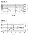
- Fig. 11 illustrates the ability of the control strategy to effectively accommodate changes in driver demand.
- a change-of-mind maneuver by the operator is shown.
- the launch begins with the accelerator pedal at about 20 percent of its maximum range.
- the accelerator pedal is held at that position for about one second, then the pedal is fully depressed to the wide open throttle position.
- the control system smoothly and quickly controls the clutch pressure and SA boost to respond to this change to provide maximum vehicle acceleration.
Landscapes
- Engineering & Computer Science (AREA)
- Chemical & Material Sciences (AREA)
- Combustion & Propulsion (AREA)
- Transportation (AREA)
- Mechanical Engineering (AREA)
- Automation & Control Theory (AREA)
- Hybrid Electric Vehicles (AREA)
- Electric Propulsion And Braking For Vehicles (AREA)
- Control Of Vehicle Engines Or Engines For Specific Uses (AREA)
Applications Claiming Priority (2)
| Application Number | Priority Date | Filing Date | Title |
|---|---|---|---|
| US780337 | 1997-01-08 | ||
| US10/780,337 US6974402B2 (en) | 2004-02-17 | 2004-02-17 | Launch control of hybrid electric vehicle having a torque converterless driveline |
Publications (2)
| Publication Number | Publication Date |
|---|---|
| EP1564055A2 true EP1564055A2 (fr) | 2005-08-17 |
| EP1564055A3 EP1564055A3 (fr) | 2006-09-06 |
Family
ID=34701446
Family Applications (1)
| Application Number | Title | Priority Date | Filing Date |
|---|---|---|---|
| EP05101130A Withdrawn EP1564055A3 (fr) | 2004-02-17 | 2005-02-15 | Commande d'un véhicule hybride lors du départ |
Country Status (2)
| Country | Link |
|---|---|
| US (1) | US6974402B2 (fr) |
| EP (1) | EP1564055A3 (fr) |
Cited By (9)
| Publication number | Priority date | Publication date | Assignee | Title |
|---|---|---|---|---|
| WO2007080034A1 (fr) | 2006-01-10 | 2007-07-19 | Continental Automotive Gmbh | Chaîne cinématique pour commande entièrement hybride, ainsi que procédé et moyen permettant de faire fonctionner la chaîne cinématique |
| WO2008064813A3 (fr) * | 2006-11-30 | 2008-07-31 | Zahnradfabrik Friedrichshafen | Module hybride pour système d'entraînement d'un véhicule |
| CN101096179B (zh) * | 2006-05-19 | 2010-09-08 | 德国Fev发动机技术有限公司 | 具有混合动力驱动系统的汽车 |
| EP2055549A3 (fr) * | 2007-10-29 | 2011-08-31 | GM Global Technology Operations LLC | Procédé et appareil pour créer une pseudo phase de couple durant une prise d'embrayage d'entrée pour empêcher un patinage de l'embrayage dans un système de transmission hybride |
| EP2186701B1 (fr) * | 2007-09-26 | 2012-02-15 | Honda Motor Co., Ltd. | Systeme auxiliaire de demarrage de vehicule |
| EP1916146A3 (fr) * | 2006-10-28 | 2012-10-31 | ZF Friedrichshafen AG | Système d'entraînement hybride pour un véhicule |
| CN101332764B (zh) * | 2007-06-07 | 2012-11-28 | 福特全球技术公司 | 混合动力车辆的起动控制 |
| US9254823B1 (en) | 2013-02-20 | 2016-02-09 | Davis Intellectual Properties LLC | Vehicle brake control system |
| US9457787B2 (en) | 2012-05-07 | 2016-10-04 | Ford Global Technologies, Llc | Method and system to manage driveline oscillations with motor torque adjustment |
Families Citing this family (23)
| Publication number | Priority date | Publication date | Assignee | Title |
|---|---|---|---|---|
| WO2003041989A2 (fr) * | 2001-11-12 | 2003-05-22 | Siemens Aktiengesellschaft | Chaîne cinématique d'un véhicule automobile et procédé de commande d'une chaîne cinématique |
| US7326149B2 (en) * | 2004-11-05 | 2008-02-05 | Ford Global Technologies, Llc | Converterless transmission shift control system |
| US8061463B2 (en) * | 2004-11-25 | 2011-11-22 | Honda Motor Co., Ltd. | Control system for hybrid vehicle |
| DE102006003713A1 (de) * | 2006-01-26 | 2007-08-02 | Zf Friedrichshafen Ag | Verfahren zur Steuerung eines Kraftfahrzeug-Antriebsstrangs |
| US7678013B2 (en) * | 2007-08-09 | 2010-03-16 | Ford Global Technologies, Llc | Launch control of a hybrid electric vehicle |
| US8296027B2 (en) * | 2007-10-25 | 2012-10-23 | GM Global Technology Operations LLC | Method and apparatus to control off-going clutch torque during torque phase for a hybrid powertrain system |
| US7998026B2 (en) * | 2008-01-17 | 2011-08-16 | Ford Global Technologies, Llc | Vehicle launch using a transmission input clutch |
| US8038573B2 (en) * | 2008-04-17 | 2011-10-18 | Bayerische Motoren Werke Aktiengesellschaft | Power development for rapid start in full-hybrid drives with optimized traction control |
| US8480772B2 (en) * | 2009-12-22 | 2013-07-09 | 3M Innovative Properties Company | Transfer assisted screen printing method of making shaped abrasive particles and the resulting shaped abrasive particles |
| CN102358159B (zh) * | 2011-08-05 | 2013-12-18 | 上海中科深江电动车辆有限公司 | 具有液力变矩器的混合驱动系统 |
| CN102358158B (zh) * | 2011-08-05 | 2013-12-11 | 上海中科深江电动车辆有限公司 | 重型车辆的混合驱动系统 |
| US9827975B2 (en) * | 2012-05-04 | 2017-11-28 | Ford Global Technologies, Llc | Methods and systems for improving transmission shifting |
| DE102013104511A1 (de) * | 2012-05-04 | 2013-11-07 | Ford Global Technologies, Llc | Verfahren und Systeme zur Verbesserung einer Getriebeschaltung |
| US8961364B2 (en) | 2012-05-07 | 2015-02-24 | Ford Global Technologies, Llc | Method and system to manage driveline oscillations with clutch pressure control |
| US8862350B2 (en) * | 2012-08-07 | 2014-10-14 | GM Global Technology Operations LLC | Method and apparatus for controlling a multi-mode powertrain system |
| US9031722B2 (en) | 2012-12-10 | 2015-05-12 | Ford Global Technologies, Llc | Method and system for improving hybrid vehicle shifting |
| US11097711B2 (en) * | 2014-04-22 | 2021-08-24 | Ford Global Technologies, Llc | Traction control for a hybrid electric powertrain |
| DE102014217667A1 (de) * | 2014-09-04 | 2016-03-10 | Zf Friedrichshafen Ag | Lageranordnung in einem Getriebegehäuse |
| KR20170058472A (ko) * | 2015-11-18 | 2017-05-29 | 현대자동차주식회사 | 하이브리드 차량의 발진 제어방법 |
| KR102463716B1 (ko) * | 2017-12-06 | 2022-11-07 | 현대자동차주식회사 | 하이브리드 차량용 변속기의 rpm 플레어 제어 방법 |
| US11097732B2 (en) | 2019-01-04 | 2021-08-24 | Ford Global Technologies, Llc | Methods and system for controlling launch of a hybrid vehicle |
| US10994734B2 (en) | 2019-06-07 | 2021-05-04 | Ford Global Technologies, Llc | Methods and system for controlling launch of a vehicle having an automatic transmission |
| DE102020003597A1 (de) * | 2020-06-17 | 2020-09-03 | FEV Europe GmbH | Paralleler Hybridantrieb für ein Kraftfahrzeug |
Family Cites Families (8)
| Publication number | Priority date | Publication date | Assignee | Title |
|---|---|---|---|---|
| GB2173273B (en) * | 1984-03-16 | 1988-07-27 | Mitsubishi Motors Corp | Automatic transmission apparatus for vehicle |
| DE4443312C2 (de) * | 1993-12-20 | 1998-07-02 | Volkswagen Ag | Verfahren zum Betrieb eines Kraftfahrzeuges |
| US6227999B1 (en) * | 1997-07-09 | 2001-05-08 | Transmisiones Tsp, S.A. De C.V. | Method and apparatus for operating a clutch in an automated mechanical transmission |
| US5993350A (en) * | 1997-12-01 | 1999-11-30 | Lawrie; Robert E. | Automated manual transmission clutch controller |
| US6176808B1 (en) | 1999-07-15 | 2001-01-23 | Ford Global Technologies, Inc. | Hybrid vehicle powertrain and control therefor |
| US6217479B1 (en) * | 1999-07-15 | 2001-04-17 | Ford Global Technologies, Inc. | Converterless multiple-ratio automatic transmission |
| DE10031312A1 (de) * | 2000-06-27 | 2002-01-10 | Mannesmann Sachs Ag | Vorrichtung zum Ausgleich eines Schleppmomentes, Verfahren zum Ansteuern der Vorrichtung und zwischen einer Brennkraftmaschine eines Kraftfahrzeuges und zumindest einem angetriebenen Rad anzuordnenden Laststrang |
| DE10204982A1 (de) * | 2002-02-06 | 2003-08-14 | Daimler Chrysler Ag | Hybridantrieb für Kraftfahrzeuge |
-
2004
- 2004-02-17 US US10/780,337 patent/US6974402B2/en not_active Expired - Fee Related
-
2005
- 2005-02-15 EP EP05101130A patent/EP1564055A3/fr not_active Withdrawn
Non-Patent Citations (1)
| Title |
|---|
| None |
Cited By (11)
| Publication number | Priority date | Publication date | Assignee | Title |
|---|---|---|---|---|
| WO2007080034A1 (fr) | 2006-01-10 | 2007-07-19 | Continental Automotive Gmbh | Chaîne cinématique pour commande entièrement hybride, ainsi que procédé et moyen permettant de faire fonctionner la chaîne cinématique |
| CN101096179B (zh) * | 2006-05-19 | 2010-09-08 | 德国Fev发动机技术有限公司 | 具有混合动力驱动系统的汽车 |
| EP1916146A3 (fr) * | 2006-10-28 | 2012-10-31 | ZF Friedrichshafen AG | Système d'entraînement hybride pour un véhicule |
| WO2008064813A3 (fr) * | 2006-11-30 | 2008-07-31 | Zahnradfabrik Friedrichshafen | Module hybride pour système d'entraînement d'un véhicule |
| CN101332764B (zh) * | 2007-06-07 | 2012-11-28 | 福特全球技术公司 | 混合动力车辆的起动控制 |
| EP2186701B1 (fr) * | 2007-09-26 | 2012-02-15 | Honda Motor Co., Ltd. | Systeme auxiliaire de demarrage de vehicule |
| EP2055549A3 (fr) * | 2007-10-29 | 2011-08-31 | GM Global Technology Operations LLC | Procédé et appareil pour créer une pseudo phase de couple durant une prise d'embrayage d'entrée pour empêcher un patinage de l'embrayage dans un système de transmission hybride |
| US8282526B2 (en) | 2007-10-29 | 2012-10-09 | GM Global Technology Operations LLC | Method and apparatus to create a pseudo torque phase during oncoming clutch engagement to prevent clutch slip for a hybrid powertrain system |
| CN101520087B (zh) * | 2007-10-29 | 2013-07-17 | 通用汽车环球科技运作公司 | 防止混合动力系统的离合器滑转的方法和设备 |
| US9457787B2 (en) | 2012-05-07 | 2016-10-04 | Ford Global Technologies, Llc | Method and system to manage driveline oscillations with motor torque adjustment |
| US9254823B1 (en) | 2013-02-20 | 2016-02-09 | Davis Intellectual Properties LLC | Vehicle brake control system |
Also Published As
| Publication number | Publication date |
|---|---|
| EP1564055A3 (fr) | 2006-09-06 |
| US6974402B2 (en) | 2005-12-13 |
| US20050181907A1 (en) | 2005-08-18 |
Similar Documents
| Publication | Publication Date | Title |
|---|---|---|
| US6974402B2 (en) | Launch control of hybrid electric vehicle having a torque converterless driveline | |
| JP3915698B2 (ja) | ハイブリッド車輌の制御装置 | |
| KR101111939B1 (ko) | 자동 변속기용 제어 장치 | |
| US7331899B2 (en) | Hybrid vehicle powertrain with a multiple-ratio power transmission mechanism | |
| EP1068977B1 (fr) | Transmission et système de commande pour un moteur à combustion dans un véhicule hybride | |
| US7770676B2 (en) | Method for operating a parallel hybrid powertrain of a vehicle with at least one internal combustion engine and at least one electric motor | |
| CN102770295B (zh) | 控制装置 | |
| US6773372B2 (en) | Vehicle drive control apparatus and method | |
| JP4845971B2 (ja) | 原動機付き車両用のパワートレイン制御方法 | |
| US8062173B2 (en) | Method for controlling a hybrid drivetrain | |
| JP5573963B2 (ja) | ハイブリッド車両の制御装置 | |
| JP3584680B2 (ja) | 内燃機関と電動機の複合型車両駆動装置 | |
| US20030004032A1 (en) | Control system for a hybrid electric vehicle to operate a pre-transmission powertrain motor in an engine emulation mode | |
| US20050250618A1 (en) | Torsional isolation of a convertless automatic transmission through slip control of friction clutch | |
| JP4807697B2 (ja) | 車両の制御装置 | |
| JP2004169867A (ja) | 車両用駆動制御装置 | |
| WO2012104993A1 (fr) | Appareil de commande de véhicule | |
| US10479182B2 (en) | Shift control system for vehicle | |
| WO2005075239A1 (fr) | Dispositif de commande du moteur d’une boite de vitesse pour un véhicule | |
| JP2013119875A (ja) | 車両の制御装置 | |
| CN101566228B (zh) | 自动变速器的控制设备 | |
| US12466388B2 (en) | Method for operating a motor vehicle drive train and electronic control unit for carrying out said method | |
| JP2005098522A (ja) | 車両用駆動制御装置 | |
| JP4051913B2 (ja) | パワートレーンの制御装置 | |
| JP7452559B2 (ja) | 車両の制御装置 |
Legal Events
| Date | Code | Title | Description |
|---|---|---|---|
| PUAI | Public reference made under article 153(3) epc to a published international application that has entered the european phase |
Free format text: ORIGINAL CODE: 0009012 |
|
| AK | Designated contracting states |
Kind code of ref document: A2 Designated state(s): AT BE BG CH CY CZ DE DK EE ES FI FR GB GR HU IE IS IT LI LT LU MC NL PL PT RO SE SI SK TR |
|
| AX | Request for extension of the european patent |
Extension state: AL BA HR LV MK YU |
|
| RAP1 | Party data changed (applicant data changed or rights of an application transferred) |
Owner name: FORD GLOBAL TECHNOLOGIES, LLC. |
|
| PUAL | Search report despatched |
Free format text: ORIGINAL CODE: 0009013 |
|
| AK | Designated contracting states |
Kind code of ref document: A3 Designated state(s): AT BE BG CH CY CZ DE DK EE ES FI FR GB GR HU IE IS IT LI LT LU MC NL PL PT RO SE SI SK TR |
|
| AX | Request for extension of the european patent |
Extension state: AL BA HR LV MK YU |
|
| 17P | Request for examination filed |
Effective date: 20070202 |
|
| 17Q | First examination report despatched |
Effective date: 20070321 |
|
| AKX | Designation fees paid |
Designated state(s): DE FR GB |
|
| GRAP | Despatch of communication of intention to grant a patent |
Free format text: ORIGINAL CODE: EPIDOSNIGR1 |
|
| STAA | Information on the status of an ep patent application or granted ep patent |
Free format text: STATUS: THE APPLICATION IS DEEMED TO BE WITHDRAWN |
|
| 18D | Application deemed to be withdrawn |
Effective date: 20110901 |