EP1564072A2 - Ausziehbarer Ladeboden für ein Fahrzeug - Google Patents
Ausziehbarer Ladeboden für ein Fahrzeug Download PDFInfo
- Publication number
- EP1564072A2 EP1564072A2 EP05002092A EP05002092A EP1564072A2 EP 1564072 A2 EP1564072 A2 EP 1564072A2 EP 05002092 A EP05002092 A EP 05002092A EP 05002092 A EP05002092 A EP 05002092A EP 1564072 A2 EP1564072 A2 EP 1564072A2
- Authority
- EP
- European Patent Office
- Prior art keywords
- loading floor
- loading
- extendable
- floor according
- arm
- Prior art date
- Legal status (The legal status is an assumption and is not a legal conclusion. Google has not performed a legal analysis and makes no representation as to the accuracy of the status listed.)
- Granted
Links
Images





Classifications
-
- B—PERFORMING OPERATIONS; TRANSPORTING
- B60—VEHICLES IN GENERAL
- B60R—VEHICLES, VEHICLE FITTINGS, OR VEHICLE PARTS, NOT OTHERWISE PROVIDED FOR
- B60R5/00—Compartments within vehicle body primarily intended or sufficiently spacious for trunks, suit-cases, or the like
- B60R5/04—Compartments within vehicle body primarily intended or sufficiently spacious for trunks, suit-cases, or the like arranged at rear of vehicle
-
- B—PERFORMING OPERATIONS; TRANSPORTING
- B60—VEHICLES IN GENERAL
- B60R—VEHICLES, VEHICLE FITTINGS, OR VEHICLE PARTS, NOT OTHERWISE PROVIDED FOR
- B60R5/00—Compartments within vehicle body primarily intended or sufficiently spacious for trunks, suit-cases, or the like
- B60R5/04—Compartments within vehicle body primarily intended or sufficiently spacious for trunks, suit-cases, or the like arranged at rear of vehicle
- B60R5/041—Compartments within vehicle body primarily intended or sufficiently spacious for trunks, suit-cases, or the like arranged at rear of vehicle extensible externally of the vehicle body, e.g. to create an open luggage compartment of increased capacity
Definitions
- the invention relates to an extendable loading floor for a vehicle, in particular for a passenger car, in a cargo or luggage compartment can be arranged and, preferably in the direction of travel of the vehicle on at least one linear bearing is slidably disposed.
- the loading floor is disadvantageous when it is not needed and large Objects to be transported in the cargo or luggage compartment of the vehicle.
- the loading floor requires a few centimeters of height, which reduces the effective loading height in the cargo or luggage compartment.
- the invention is therefore based on the object , a vehicle with an extendable loading floor of the type mentioned in such a way that the loading floor is available when needed, but that it represents no restriction on the loading capacity of the cargo or luggage compartment when not in use and in particular the available loading height not limited.
- the solution of this problem by the invention is characterized in that the loading floor consists of at least two parts which are formed hinged relative to each other.
- Another training provides that at least two parts of the loading floor are connected by a hinge.
- latching means at least a part of the loading floor arranged, with which two parts of the loading floor in can be locked in a defined co-operating position.
- a particularly preferred embodiment provides that the loading floor of four Parts consists, of which two parts are connected by a hinge.
- At least two parts of the loading floor in collapsed state folded into a vertically oriented position can be.
- locking means may be present, which are the parts of the Loading floor in folded state in vertically aligned position hold.
- the loading floor created a cover for the wheel arches of the motor vehicle which defines a storage space for accessories (warning triangle, first-aid kit, etc.), so that in case that the loading floor is not needed, the remaining load or trunk of such parts is kept free.
- the folded-up loading floor otherwise existing cover elements for the wheel arches.
- Loading floors of the generic type are usually designed for weights that in the range of about 150 kg. This makes it very easy possible to handle relatively bulky and heavy objects, for example a washing machine. Stands the vehicle in which a heavy object on the Loading floor is transported, in a slightly inclined position, for example, on a Hang, this has the consequence that a not insignificant horizontal component of Weight acts on the loading floor, which tries to clear the loading floor from the To push out cargo or trunk. Under particularly unfavorable Circumstances, i. when the vehicle is uphill on a slope, it gets lost Circumstances to an undesirable Ausschubiolo the loading floor Direction of travel when the tailgate of the passenger car is opened, what represents a not insignificant danger potential.
- the Loading floor is provided with means with which he relative to the loading or Trunk can be fixed immovable.
- the means comprise an active element which is between the loading or Trunk and the loading floor a force, friction or positive connection can produce.
- a further development provides that the active element as on or in the loading floor arranged and hinged about a arranged on or in the loading floor axis of rotation mounted arm is formed. It is especially provided that the arm its one end has a section which with one at the loading or Trunk firmly arranged counter section force, friction or positive can interact.
- the portion of the arm a Friction surface forms, which can rub against the opposite portion.
- the portion of the arm a Projection forms in one or more recesses in the opposite section can intervene positively. Preference is given to the projection of the arm tooth-shaped, wherein the recesses in the opposite section according to Art a rack are formed.
- the means for fixing the loading floor relative to the loading or trunk on other end of the arm comprise a lifting element with which the end in a for Moving direction of the loading floor vertical direction, preferably in Direction of the vertical, can be moved.
- the lifting element can thereby a slider which is relative to the loading floor, in particular in Moving direction of the loading floor, is arranged slidably and a Actuating surface, the other end of the arm in a for Moving direction of the loading floor vertical direction, preferably in Direction of the vertical, can move.
- a structurally particularly compact design is achieved when the Actuating surface of the slider is designed as a wedge surface, with a complementarily shaped counter wedge surface at the other end of the arm can interact.
- the slider can by means of a spring element in one direction, in particular in the direction of the loading floor, be biased.
- spring element comes preferably uses a coil spring concentric about a rod is arranged, wherein the rod is set in the loading floor that its axis in Direction of displacement of the slider in the loading floor points.
- the arrangement can be be executed so that the spring element, the means for fixing the Reload loading floor relative to the loading or trunk so that the loading floor is set relative to the cargo or luggage compartment.
- the transmission element is the rod for concentric guidance the spiral spring is used.
- the bumper bar-shaped is, with their longitudinal axis transverse to the direction of travel in a horizontal Level at the rear end of the loading floor seen in the direction of displacement of the loading floor Loading floor extends.
- the bumper can essentially over the extend the entire width of the loading floor.
- Figures 1 and 2 is the rear portion of a passenger car represented, namely the loading or trunk 1 of the car.
- Loading floor 2 arranged, with the tailgate of the passenger car open can be pulled out in a direction of displacement, these in the Embodiments with the direction of travel F of the vehicle coincides.
- the loading floor 2 is designed to be foldable.
- Four parts 2a, 2b, 2c and 2d of Loading floor 2 are in use of the loading floor 2 next to each other and form so the bearing surface for the goods to be transported.
- two parts of the Loading floor namely the parts 2a and 2b or the parts 2c and 2d, by means of one each Hinge 21 hinged together, the folding axis 20 of the Hinge 21 in the direction of displacement of the loading floor 2, i. in the Embodiment in the direction of travel F, points.
- locking means 23 are provided, which in Embodiment consist of a sliding pin which transversely to Shifting direction of the loading floor 2 from the part 2b of the loading floor. 2 can be pushed out so that he in holes not shown in part 2c of the loading floor 2 engages. The parts 2b and 2c of the loading floor 2 can thus in folded down state of the loading floor 2 are locked so that both Parts form a stable plate.
- the loading floor 2 in the direction of travel F of Motor vehicle can be pulled out with the tailgate open.
- linear bearing 3 is provided, which at the two lateral ends of the loading floor 2 are arranged.
- the linear bearings 3 exist each of two guide rails, between which balls are arranged.
- the Balls are guided by a cage, which moves in the direction of displacement of the Loading floor 2 extends linearly over a defined length. This creates a Linear bearing 3, which allows only a limited linear displacement, which is chosen that the desired pull-out path for the loading floor 2 is given.
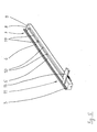
- FIG 3 one half of the loading floor 2 is shown with the parts 2a and 2b.
- an active element 5 in the form of a hinged stored arm is housed.
- An axis of rotation 6, in part 2a of the Loading floor 2 is fixed, the arm 5 so that it rotates about this axis is.
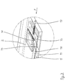
- a portion 8 is arranged to the Cooperation with a counter section 9 (see Figure 4 and Figure 5) is designed. In particular, it comes to a force, friction or positive Cooperation of the section 8 of the arm 5 and the counter portion 9, wherein the counter portion 9 relative to the loading or trunk 1 fixed and immovable is arranged.
- FIG. 5 shows an alternative embodiment, in which case no friction, but a Positive fit is used.
- the section 8 of the arm 5 as Formed projection, which in corresponding recesses 10 in the opposite section 9 can engage in the desired positions.
- a corresponding number Recesses 10 are in the opposite section 9 at a defined distance arranged to each other so that the loading floor 2 in different Detent positions relative to the loading or trunk 1 can be locked.
- a further embodiment according to the section 8 of the arm 5 is formed as a tooth and with recesses 10 in the opposite section 9 of Art a rack interacts. This allows a positive determination the loading floor 2 can be accomplished in a variety of positions.
- the lifting element 12 is in the embodiment of two sliders 13, the in Moving direction of the loading floor 2 (direction of travel F) displaceable in each one Part of the loading floor 2, namely in the parts 2 a and 2 d of the loading floor 2, stored are.
- On the slider 13 is a wedge-shaped actuating surface 14th provided with a counter-wedge surface 15 at the end 11 of the arm. 5 interacts. This ensures that upon displacement of the slide 13 in Direction of the axis of rotation 6, the desired locking or clamping position of the Arms 5 is initiated, so that the loading floor 2 relative to the loading or Trunk 1 is immovable.
- the slider 13 from the rotation axis. 6 moved away, the arm 5 is relieved at its end 11, so that the force, frictional or positive connection between sections 8 and 9 will be annulled. Not shown is that in this case one in vertical Direction V acting spring moves the arm 5 in the unlocked position.
- a Spring element 16 provided in the form of a coil spring which is not actuated State of the slide biases this towards the axis of rotation 6 and so on Locking or locking of the loading floor 2 accomplished.
- To unlock the loading floor for the purpose of pulling out of the cargo or luggage compartment 1 are the two slides 13 in the parts 2a and 2d of the loading floor 2 on a handle 18th taken and pulled away from the axis of rotation 6 away. This is done against the resistance the coil spring 16.
- the arm 5 is thus released at its end 11 so that the locking or locking of the loading floor 2 is released; of the Loading floor 2 can be moved relative to the loading or trunk 1 be pulled out and inserted.
- Be the handles 18 on the sliders 13th However, let go again, causes the coil spring 16 via the actuating surface fourteenth and the counter-wedge surface 15 jamming or locking the loading floor. 2
- the coil spring 16 is on a rod 17th stored, with the axis of the rod 17 in the direction of the loading floor 2 (direction of travel F) extends.
- the rod 17 as a transmission element formed through the rear end of the loading floor 2, i. through the part 2a of the loading floor 2, extends therethrough, wherein at the end of the rod 17 a Bumper strip 19 is arranged.
- This bumper is in Figures 8 and 9 to detect.
- the bumper strip 19 arranged on the rod 17 on the slide 13 that when exercising a Pressure force D on the bumper 19 of the slide 13 in Arret ists- or Clamping position is moved.
- linear bearings 3 come. Preference is given to a fixed in the loading or trunk 1 Rail 24 a guide rail 25 of the linear bearing arranged (see Figure 4). In the parts 2a and 2d of the loading floor 2 are the corresponding, not arranged counter-guide rails of the linear bearing 3, wherein between the guide rail 25 and the counter guide rail balls are arranged.
Landscapes
- Engineering & Computer Science (AREA)
- Mechanical Engineering (AREA)
- Vehicle Step Arrangements And Article Storage (AREA)
- Auxiliary Methods And Devices For Loading And Unloading (AREA)
- Refuge Islands, Traffic Blockers, Or Guard Fence (AREA)
- Body Structure For Vehicles (AREA)
- Fittings On The Vehicle Exterior For Carrying Loads, And Devices For Holding Or Mounting Articles (AREA)
Abstract
Description
- Figur 1
- in dreidimensionaler Ansicht den Blick in einen Kofferraum eines Personenkraftwagens, in dem ein klappbar ausgebildeter Ladeboden angeordnet ist,
- Figur 2
- dieselbe Anordnung wie in Figur 1 aus einem anderen Blickwinkel,
- Figur 3
- in perspektivischer Ansicht einen Teil des Ladebodens,
- Figur 4
- in perspektivischer Ansicht einen Teil des Linearlagers samt einem Teil der Mittel zum Festlegen des Ladebodens relativ zum Lade- oder Kofferraum gemäß einer ersten Ausgestaltung,
- Figur 5
- die zu Figur 4 analoge Darstellung in einer alternativen Ausgestaltung,
- Figur 6
- in perspektivischer Darstellung den Endabschnitt des Ladebodens mit einem Teil der Mittel zum Festlegen des Ladebodens relativ zum Lade- oder Kofferraum in der Stellung, in der der Ladeboden relativ zum Lade- oder Kofferraum festgelegt ist,
- Figur 7
- die zu Figur 6 analoge Darstellung, wobei die Linearbewegung des Ladebodens relativ zum Lade- oder Kofferraum freigegeben ist,
- Figur 8
- die Draufsicht auf den Ladeboden im Lade- oder Kofferraum und
- Figur 9
- den Schnitt A-A gemäß Figur 8.
- 1
- Lade- oder Kofferraum
- 2
- Ladeboden
- 2a
- Teil des Ladebodens
- 2b
- Teil des Ladebodens
- 2c
- Teil des Ladebodens
- 2d
- Teil des Ladebodens
- 3
- Linearlager
- 4
- Mittel zum Festlegen des Ladebodens relativ zum Lade- oder Kofferraum
- 5
- Wirkelement (Arm)
- 6
- Drehachse
- 7
- Ende des Arms
- 8
- Abschnitt des Arms
- 9
- Gegenabschnitt
- 10
- Ausnehmung im Gegenabschnitt
- 11
- Ende des Arms
- 12
- Hubelement
- 13
- Schieber
- 14
- Betätigungsfläche
- 15
- Gegenkeilfläche
- 16
- Federelement (Spiralfeder)
- 17
- Stange, Übertragungselement
- 18
- Griff
- 19
- Stoßleiste
- 20
- Klappachse
- 21
- Scharnier
- 22
- Boden des Lade- oder Kofferraums
- 23
- Riegelmittel
- 24
- Schiene
- 25
- Führungsschiene
- F
- Fahrtrichtung
- V
- Vertikale
- D
- Druckkraft
Claims (28)
- Ausziehbarer Ladeboden für ein Fahrzeug, insbesondere für einen Personenkraftwagen, der in einem Lade- oder Kofferraum (1) angeordnet werden kann und der, vorzugsweise in Fahrtrichtung (F) des Fahrzeugs, auf mindestens einem Linearlager (3) verschiebbar angeordnet ist, dadurch gekennzeichnet, dass der Ladeboden (2) aus mindestens zwei Teilen (2a, 2b, 2c, 2d) besteht, die relativ zueinander klappbar ausgebildet sind.
- Ausziehbarer Ladeboden nach Anspruch 1, dadurch gekennzeichnet, dass die Klappachse (20) zwischen den Teilen (2a, 2b, 2c, 2d) in Verschieberichtung des Ladebodens (2) weist.
- Ausziehbarer Ladeboden nach Anspruch 1 oder 2, dadurch gekennzeichnet, dass zumindest zwei Teile (2a, 2b; 2c, 3d) des Ladebodens (2) mit einem Scharnier (21) verbunden sind.
- Ausziehbarer Ladeboden nach einem der Ansprüche 1 bis 3, dadurch gekennzeichnet, dass Riegelmittel (23) an mindestens einem Teil (2b) des Ladebodens (2) angeordnet sind, mit denen zwei Teile (2b, 2c) des Ladebodens (2) in einer definierten zusammenwirkenden Position verriegelt werden können.
- Ausziehbarer Ladeboden nach Anspruch 4, dadurch gekennzeichnet, dass die Riegelmittel (23) aus einem in einem Teil (2b) des Ladebodens (2) verschieblich gelagerten Stift bestehen, der in eine korrespondierende Bohrung in einem anderen Teil (2c) des Ladebodens (2) eindringen kann.
- Ausziehbarer Ladeboden nach Anspruch 5, dadurch gekennzeichnet, dass der Stift in eine Richtung quer zur Verschieberichtung des Ladebodens (2) verschieblich gelagert ist.
- Ausziehbarer Ladeboden nach einem der Ansprüche 1 bis 6, dadurch gekennzeichnet, dass der Ladeboden (2) aus vier Teilen (2a, 2b, 2c, 2d) besteht, von denen jeweils zwei Teile (2a, 2b; 2c, 3d) mit einem Scharnier (21) verbunden sind.
- Ausziehbarer Ladeboden nach einem der Ansprüche 1 bis 7, dadurch gekennzeichnet, dass zumindest zwei Teile (2a, 2b; 2c, 2d) des Ladebodens (2) in zusammengeklapptem Zustand in eine vertikal ausgerichtete Position geklappt werden können.
- Ausziehbarer Ladeboden nach Anspruch 8, dadurch gekennzeichnet, dass Rastmittel vorhanden sind, die die Teile (2a, 2b; 2c, 2d) des Ladebodens (2) in zusammengeklapptem Zustand in vertikal ausgerichteter Position halten.
- Ausziehbarer Ladeboden nach einem der Ansprüche 1 bis 9, dadurch gekennzeichnet, dass der Ladeboden (2) mit Mitteln (4) versehen ist, mit denen er relativ zum Lade- oder Kofferraum (1) unverschiebbar festgelegt werden kann.
- Ausziehbarer Ladeboden nach Anspruch 10, dadurch gekennzeichnet, dass die Mittel (4) ein Wirkelement (5) aufweisen, das zwischen dem Lade- oder Kofferraum (1) und dem Ladeboden (2) eine kraft-, reib- oder formschlüssige Verbindung herstellen können.
- Ausziehbarer Ladeboden nach Anspruch 10 oder 11, dadurch gekennzeichnet, dass das Wirkelement (5) als am oder im Ladeboden (2) angeordneter und um eine am oder im Ladeboden (2) angeordnete Drehachse (6) gelenkig gelagerter Arm (5) ausgebildet ist.
- Ausziehbarer Ladeboden nach Anspruch 12, dadurch gekennzeichnet, dass der Arm (5) an seinem einen Ende (7) einen Abschnitt (8) aufweist, der mit einem am Lade- oder Kofferraum (1) fest angeordneten Gegenabschnitt (9) kraft-, reib- oder formschlüssig zusammenwirken kann.
- Ausziehbarer Ladeboden nach Anspruch 13, dadurch gekennzeichnet, dass der Abschnitt (8) des Arms (5) eine Reibfläche bildet, die an dem Gegenabschnitt (9) reibend anliegen kann.
- Ausziehbarer Ladeboden nach Anspruch 13, dadurch gekennzeichnet, dass der Abschnitt (8) des Arms (5) einen Vorsprung bildet, der in eine oder mehrere Ausnehmungen (10) im Gegenabschnitt (9) formschlüssig eingreifen kann.
- Ausziehbarer Ladeboden nach Anspruch 15, dadurch gekennzeichnet, dass der Vorsprung (8) des Arms (5) zahnförmig ausgebildet ist und die Ausnehmungen (10) im Gegenabschnitt (9) nach Art einer Zahnstange ausgebildet sind.
- Ausziehbarer Ladeboden nach einem der Ansprüche 12 bis 16, dadurch gekennzeichnet, dass die Mittel (4) am anderen Ende (11) des Arms (5) ein Hubelement (12) umfassen, mit dem das Ende (11) in eine zur Verschieberichtung des Ladebodens (2) senkrechte Richtung, vorzugsweise in Richtung der Vertikalen (V), verschoben werden kann.
- Ausziehbarer Ladeboden nach Anspruch 17, dadurch gekennzeichnet, dass das Hubelement (12) einen Schieber (13) umfasst, der relativ zum Ladeboden (2), insbesondere in Verschieberichtung des Ladebodens (2), verschiebbar angeordnet ist und eine Betätigungsfläche (14) aufweist, die das andere Ende (11) des Arms (5) in eine zur Verschieberichtung des Ladebodens (2) senkrechte Richtung, vorzugsweise in Richtung der Vertikalen (V), verschieben kann.
- Ausziehbarer Ladeboden nach Anspruch 18, dadurch gekennzeichnet, dass die Betätigungsfläche (14) des Schiebers (13) als Keilfläche ausgebildet ist, die mit einer komplementär ausgeformten Gegenkeilfläche (15) am anderen Ende (11) des Arms (5) zusammenwirken kann.
- Ausziehbarer Ladeboden nach Anspruch 18 oder 19, dadurch gekennzeichnet, dass der Schieber (13) mittels eines Federelements (16) in eine Richtung, insbesondere in Verschieberichtung des Ladebodens (2), vorgespannt ist.
- Ausziehbarer Ladeboden nach Anspruch 20, dadurch gekennzeichnet, dass das Federelement (16) eine Spiralfeder ist, die konzentrisch um eine Stange (17) angeordnet ist, wobei die Stange (17) so im Ladeboden (2) festgelegt ist, dass ihre Achse in Verschieberichtung des Schiebers (13) im Ladeboden (2) weist.
- Ausziehbarer Ladeboden nach Anspruch 20 oder 21, dadurch gekennzeichnet, dass das Federelement (16) die Mittel (4) so vorspannen, dass der Ladeboden (2) relativ zum Lade- oder Kofferraum (1) festgelegt wird.
- Ausziehbarer Ladeboden nach einem der Ansprüche 18 bis 22, dadurch gekennzeichnet, dass am Schieber (13) ein Griff oder Druckknopf (18) angeordnet ist.
- Ausziehbarer Ladeboden nach einem der Ansprüche 17 bis 23, dadurch gekennzeichnet, dass am Hubelement (12), insbesondere am Schieber (13), mindestens ein Übertragungselement (17) mit seinem einen Ende angeordnet ist, das den Ladeboden (2) durchsetzt und an seinem anderen Ende eine Stoßleiste (19) trägt.
- Ausziehbarer Ladeboden nach Anspruch 24, dadurch gekennzeichnet, dass das Übertragungselement (17) die Stange ist, die zur konzentrischen Führung der Spiralfeder (16) dient.
- Ausziehbarer Ladeboden nach Anspruch 24 oder 25, dadurch gekennzeichnet, dass die Stoßleiste (19) balkenförmig ausgebildet ist, wobei sie sich mit ihrer Längsachse quer zur Verschieberichtung des Ladebodens (2) in einer horizontalen Ebene am in Verschieberichtung des Ladebodens (2) gesehen hinteren und/oder vorderen Ende des Ladebodens (2) erstreckt.
- Ausziehbarer Ladeboden nach einem der Ansprüche 24 bis 26, dadurch gekennzeichnet, dass die Stoßleiste (19) sich im wesentlichen über die gesamte Breite des Ladebodens (2) erstreckt.
- Ausziehbarer Ladeboden nach einem der Ansprüche 1 bis 27, dadurch gekennzeichnet, dass das Linearlager (3) zwei Führungsschienen aufweist, zwischen denen Wälzkörper, insbesondere Kugeln, angeordnet sind, die von einem Käfig geführt werden, der sich in Verschieberichtung des Ladebodens (2) über eine definierte Länge erstreckt.
Applications Claiming Priority (2)
| Application Number | Priority Date | Filing Date | Title |
|---|---|---|---|
| DE102004007138A DE102004007138A1 (de) | 2004-02-12 | 2004-02-12 | Ausziehbarer Ladeboden für ein Fahrzeug |
| DE102004007138 | 2004-02-12 |
Publications (3)
| Publication Number | Publication Date |
|---|---|
| EP1564072A2 true EP1564072A2 (de) | 2005-08-17 |
| EP1564072A3 EP1564072A3 (de) | 2007-02-14 |
| EP1564072B1 EP1564072B1 (de) | 2009-08-05 |
Family
ID=34684043
Family Applications (1)
| Application Number | Title | Priority Date | Filing Date |
|---|---|---|---|
| EP05002092A Expired - Lifetime EP1564072B1 (de) | 2004-02-12 | 2005-02-02 | Ausziehbarer Ladeboden für ein Fahrzeug |
Country Status (3)
| Country | Link |
|---|---|
| EP (1) | EP1564072B1 (de) |
| AT (1) | ATE438539T1 (de) |
| DE (2) | DE102004007138A1 (de) |
Cited By (2)
| Publication number | Priority date | Publication date | Assignee | Title |
|---|---|---|---|---|
| ITUB20154956A1 (it) * | 2015-10-29 | 2017-04-29 | Fca Italy Spa | Piano di carico mobile per un baule di un autoveicolo |
| DE102022132129A1 (de) * | 2022-12-05 | 2024-06-06 | Audi Aktiengesellschaft | Laderaumanordnung mit dichtender Abdeckung für Frontbereich eines Fahrzeugs |
Families Citing this family (1)
| Publication number | Priority date | Publication date | Assignee | Title |
|---|---|---|---|---|
| DE102004041542A1 (de) | 2004-08-27 | 2006-03-02 | Aktiebolaget Skf | Ausziehbarer Ladeboden für ein Fahrzeug |
Citations (3)
| Publication number | Priority date | Publication date | Assignee | Title |
|---|---|---|---|---|
| WO2003022633A2 (en) | 2001-09-10 | 2003-03-20 | Textron Automotive Company Inc. | Moveable load floor for automotive applica tions |
| EP1332918A2 (de) | 2002-01-29 | 2003-08-06 | Webasto Vehicle Systems International GmbH | Kraftfahrzeug mit einem verlängebarem Laderaum und einer Laderaumtür |
| DE10210884A1 (de) | 2002-03-12 | 2003-10-23 | Opel Adam Ag | Rolloladeboden für den Laderaum eines Fahrzeuges |
Family Cites Families (5)
| Publication number | Priority date | Publication date | Assignee | Title |
|---|---|---|---|---|
| DE8714368U1 (de) * | 1987-10-28 | 1989-03-02 | Specht, Carl-Heinz, 8000 München | Ladegerät für ein Transportfahrzeug |
| AT404459B (de) * | 1996-11-18 | 1998-11-25 | Magna Eybl Gmbh | Ladeboden für den laderaum eines fahrzeuges |
| DE20014050U1 (de) * | 2000-08-16 | 2002-01-10 | Johnson Controls GmbH, 51399 Burscheid | System zur Unterbringung von Ladegut in einem Fahrzeug |
| DE10203539B4 (de) * | 2002-01-29 | 2010-01-14 | Webasto Ag | Kraftfahrzeug mit einem Laderaum und einer Laderaumtür |
| DE10214252A1 (de) * | 2002-03-30 | 2003-10-16 | Opel Adam Ag | Fahrzeug mit aus schwenkbar miteinander verbundenen Ladebodenteilen gebildetem Ladeboden |
-
2004
- 2004-02-12 DE DE102004007138A patent/DE102004007138A1/de not_active Withdrawn
-
2005
- 2005-02-02 AT AT05002092T patent/ATE438539T1/de not_active IP Right Cessation
- 2005-02-02 EP EP05002092A patent/EP1564072B1/de not_active Expired - Lifetime
- 2005-02-02 DE DE502005007822T patent/DE502005007822D1/de not_active Expired - Lifetime
Patent Citations (3)
| Publication number | Priority date | Publication date | Assignee | Title |
|---|---|---|---|---|
| WO2003022633A2 (en) | 2001-09-10 | 2003-03-20 | Textron Automotive Company Inc. | Moveable load floor for automotive applica tions |
| EP1332918A2 (de) | 2002-01-29 | 2003-08-06 | Webasto Vehicle Systems International GmbH | Kraftfahrzeug mit einem verlängebarem Laderaum und einer Laderaumtür |
| DE10210884A1 (de) | 2002-03-12 | 2003-10-23 | Opel Adam Ag | Rolloladeboden für den Laderaum eines Fahrzeuges |
Cited By (3)
| Publication number | Priority date | Publication date | Assignee | Title |
|---|---|---|---|---|
| ITUB20154956A1 (it) * | 2015-10-29 | 2017-04-29 | Fca Italy Spa | Piano di carico mobile per un baule di un autoveicolo |
| EP3162637A1 (de) | 2015-10-29 | 2017-05-03 | FCA Italy S.p.A. | Beweglicher ladeboden für einen kraftfahrzeugkofferraum |
| DE102022132129A1 (de) * | 2022-12-05 | 2024-06-06 | Audi Aktiengesellschaft | Laderaumanordnung mit dichtender Abdeckung für Frontbereich eines Fahrzeugs |
Also Published As
| Publication number | Publication date |
|---|---|
| ATE438539T1 (de) | 2009-08-15 |
| EP1564072A3 (de) | 2007-02-14 |
| DE102004007138A1 (de) | 2005-09-15 |
| DE502005007822D1 (de) | 2009-09-17 |
| EP1564072B1 (de) | 2009-08-05 |
Similar Documents
| Publication | Publication Date | Title |
|---|---|---|
| DE19513520C1 (de) | Kraftfahrzeug mit einer Heckklappe, insbesondere für Mehrzweck- oder Kombiwagen | |
| DE102009018430B4 (de) | Schiebetürsystem für ein Fahrzeug | |
| EP1396382B1 (de) | Laderaumabdeckung für Kraftwagen, insbesondere für Kombinations-Personenkraftwagen | |
| WO2008046461A1 (de) | Staufacheinrichtung für fahrzeuge | |
| EP1309470B1 (de) | System zur unterbringung von ladegut in einem fahrzeug | |
| EP1524152A1 (de) | Laderaumabdeckung | |
| DE3922450A1 (de) | Abdeckrollo | |
| DE102006000619B4 (de) | Federbelastete Klinkensperre mit automatischer Rückstellung | |
| DE1290829B (de) | Schiebetuer fuer Fahrzeuge, insbesondere Gueterwagen | |
| EP2781429B1 (de) | Fahrzeug und Einkaufswagen | |
| EP1564072B1 (de) | Ausziehbarer Ladeboden für ein Fahrzeug | |
| DE102012011223A1 (de) | Ladebodenanordnung für einen Kraftwagen | |
| DE102018126380B4 (de) | Lastaufnahmevorrichtung und Lastaufnahmesystem | |
| EP1564068B1 (de) | Ausziehbarer Ladeboden für ein Fahrzeug | |
| DE19944622A1 (de) | Kraftfahrzeug mit einem Gepäckraum | |
| DE102018214491A1 (de) | Bett für ein Kraftfahrzeug | |
| EP4031435B1 (de) | Transportwagen und verfahren zum transformieren eines transportwagens | |
| EP1632397B1 (de) | Ausziehbarer Ladeboden für ein Fahrzeug | |
| DE20307880U1 (de) | Vorrichtung zum Anheben von Lasten im Kofferraum von Kraftfahrzeugen | |
| DE102018008614A1 (de) | Schubladenanordnung für einen Fahrzeugsitz | |
| DE102021210485B4 (de) | Umklappbare KFZ-Sitzanordnung mit verstellbarer Rückhaltevorrichtung zur Sicherung einer Ladung | |
| DE102005027510A1 (de) | Ladeboden für einen Laderaum eines Fahrzeugs | |
| DE3713028C2 (de) | ||
| DE102013022154A1 (de) | Abdeckvorrichtung | |
| DE102023127296B3 (de) | Laderaumabdeckung mit veränderlicher länge |
Legal Events
| Date | Code | Title | Description |
|---|---|---|---|
| PUAI | Public reference made under article 153(3) epc to a published international application that has entered the european phase |
Free format text: ORIGINAL CODE: 0009012 |
|
| AK | Designated contracting states |
Kind code of ref document: A2 Designated state(s): AT BE BG CH CY CZ DE DK EE ES FI FR GB GR HU IE IS IT LI LT LU MC NL PL PT RO SE SI SK TR |
|
| AX | Request for extension of the european patent |
Extension state: AL BA HR LV MK YU |
|
| PUAL | Search report despatched |
Free format text: ORIGINAL CODE: 0009013 |
|
| AK | Designated contracting states |
Kind code of ref document: A3 Designated state(s): AT BE BG CH CY CZ DE DK EE ES FI FR GB GR HU IE IS IT LI LT LU MC NL PL PT RO SE SI SK TR |
|
| AX | Request for extension of the european patent |
Extension state: AL BA HR LV MK YU |
|
| 17P | Request for examination filed |
Effective date: 20070224 |
|
| 17Q | First examination report despatched |
Effective date: 20070402 |
|
| AKX | Designation fees paid |
Designated state(s): AT BE BG CH CY CZ DE DK EE ES FI FR GB GR HU IE IS IT LI LT LU MC NL PL PT RO SE SI SK TR |
|
| GRAP | Despatch of communication of intention to grant a patent |
Free format text: ORIGINAL CODE: EPIDOSNIGR1 |
|
| GRAS | Grant fee paid |
Free format text: ORIGINAL CODE: EPIDOSNIGR3 |
|
| GRAA | (expected) grant |
Free format text: ORIGINAL CODE: 0009210 |
|
| AK | Designated contracting states |
Kind code of ref document: B1 Designated state(s): AT BE BG CH CY CZ DE DK EE ES FI FR GB GR HU IE IS IT LI LT LU MC NL PL PT RO SE SI SK TR |
|
| REG | Reference to a national code |
Ref country code: GB Ref legal event code: FG4D Free format text: NOT ENGLISH |
|
| REG | Reference to a national code |
Ref country code: CH Ref legal event code: EP |
|
| REG | Reference to a national code |
Ref country code: IE Ref legal event code: FG4D |
|
| REF | Corresponds to: |
Ref document number: 502005007822 Country of ref document: DE Date of ref document: 20090917 Kind code of ref document: P |
|
| LTIE | Lt: invalidation of european patent or patent extension |
Effective date: 20090805 |
|
| PG25 | Lapsed in a contracting state [announced via postgrant information from national office to epo] |
Ref country code: SE Free format text: LAPSE BECAUSE OF FAILURE TO SUBMIT A TRANSLATION OF THE DESCRIPTION OR TO PAY THE FEE WITHIN THE PRESCRIBED TIME-LIMIT Effective date: 20090805 Ref country code: ES Free format text: LAPSE BECAUSE OF FAILURE TO SUBMIT A TRANSLATION OF THE DESCRIPTION OR TO PAY THE FEE WITHIN THE PRESCRIBED TIME-LIMIT Effective date: 20091116 Ref country code: IS Free format text: LAPSE BECAUSE OF FAILURE TO SUBMIT A TRANSLATION OF THE DESCRIPTION OR TO PAY THE FEE WITHIN THE PRESCRIBED TIME-LIMIT Effective date: 20091205 Ref country code: FI Free format text: LAPSE BECAUSE OF FAILURE TO SUBMIT A TRANSLATION OF THE DESCRIPTION OR TO PAY THE FEE WITHIN THE PRESCRIBED TIME-LIMIT Effective date: 20090805 Ref country code: LT Free format text: LAPSE BECAUSE OF FAILURE TO SUBMIT A TRANSLATION OF THE DESCRIPTION OR TO PAY THE FEE WITHIN THE PRESCRIBED TIME-LIMIT Effective date: 20090805 |
|
| NLV1 | Nl: lapsed or annulled due to failure to fulfill the requirements of art. 29p and 29m of the patents act | ||
| PG25 | Lapsed in a contracting state [announced via postgrant information from national office to epo] |
Ref country code: NL Free format text: LAPSE BECAUSE OF FAILURE TO SUBMIT A TRANSLATION OF THE DESCRIPTION OR TO PAY THE FEE WITHIN THE PRESCRIBED TIME-LIMIT Effective date: 20090805 Ref country code: SI Free format text: LAPSE BECAUSE OF FAILURE TO SUBMIT A TRANSLATION OF THE DESCRIPTION OR TO PAY THE FEE WITHIN THE PRESCRIBED TIME-LIMIT Effective date: 20090805 Ref country code: PL Free format text: LAPSE BECAUSE OF FAILURE TO SUBMIT A TRANSLATION OF THE DESCRIPTION OR TO PAY THE FEE WITHIN THE PRESCRIBED TIME-LIMIT Effective date: 20090805 |
|
| REG | Reference to a national code |
Ref country code: IE Ref legal event code: FD4D |
|
| PG25 | Lapsed in a contracting state [announced via postgrant information from national office to epo] |
Ref country code: PT Free format text: LAPSE BECAUSE OF FAILURE TO SUBMIT A TRANSLATION OF THE DESCRIPTION OR TO PAY THE FEE WITHIN THE PRESCRIBED TIME-LIMIT Effective date: 20091205 Ref country code: BG Free format text: LAPSE BECAUSE OF FAILURE TO SUBMIT A TRANSLATION OF THE DESCRIPTION OR TO PAY THE FEE WITHIN THE PRESCRIBED TIME-LIMIT Effective date: 20091105 |
|
| PG25 | Lapsed in a contracting state [announced via postgrant information from national office to epo] |
Ref country code: RO Free format text: LAPSE BECAUSE OF FAILURE TO SUBMIT A TRANSLATION OF THE DESCRIPTION OR TO PAY THE FEE WITHIN THE PRESCRIBED TIME-LIMIT Effective date: 20090805 Ref country code: DK Free format text: LAPSE BECAUSE OF FAILURE TO SUBMIT A TRANSLATION OF THE DESCRIPTION OR TO PAY THE FEE WITHIN THE PRESCRIBED TIME-LIMIT Effective date: 20090805 Ref country code: EE Free format text: LAPSE BECAUSE OF FAILURE TO SUBMIT A TRANSLATION OF THE DESCRIPTION OR TO PAY THE FEE WITHIN THE PRESCRIBED TIME-LIMIT Effective date: 20090805 Ref country code: CZ Free format text: LAPSE BECAUSE OF FAILURE TO SUBMIT A TRANSLATION OF THE DESCRIPTION OR TO PAY THE FEE WITHIN THE PRESCRIBED TIME-LIMIT Effective date: 20090805 Ref country code: IE Free format text: LAPSE BECAUSE OF FAILURE TO SUBMIT A TRANSLATION OF THE DESCRIPTION OR TO PAY THE FEE WITHIN THE PRESCRIBED TIME-LIMIT Effective date: 20090805 |
|
| PG25 | Lapsed in a contracting state [announced via postgrant information from national office to epo] |
Ref country code: SK Free format text: LAPSE BECAUSE OF FAILURE TO SUBMIT A TRANSLATION OF THE DESCRIPTION OR TO PAY THE FEE WITHIN THE PRESCRIBED TIME-LIMIT Effective date: 20090805 |
|
| PLBE | No opposition filed within time limit |
Free format text: ORIGINAL CODE: 0009261 |
|
| STAA | Information on the status of an ep patent application or granted ep patent |
Free format text: STATUS: NO OPPOSITION FILED WITHIN TIME LIMIT |
|
| 26N | No opposition filed |
Effective date: 20100507 |
|
| BERE | Be: lapsed |
Owner name: A.B. SKF Effective date: 20100228 |
|
| REG | Reference to a national code |
Ref country code: CH Ref legal event code: PL |
|
| GBPC | Gb: european patent ceased through non-payment of renewal fee |
Effective date: 20100202 |
|
| PG25 | Lapsed in a contracting state [announced via postgrant information from national office to epo] |
Ref country code: GR Free format text: LAPSE BECAUSE OF FAILURE TO SUBMIT A TRANSLATION OF THE DESCRIPTION OR TO PAY THE FEE WITHIN THE PRESCRIBED TIME-LIMIT Effective date: 20091106 Ref country code: LI Free format text: LAPSE BECAUSE OF NON-PAYMENT OF DUE FEES Effective date: 20100228 Ref country code: CH Free format text: LAPSE BECAUSE OF NON-PAYMENT OF DUE FEES Effective date: 20100228 Ref country code: MC Free format text: LAPSE BECAUSE OF NON-PAYMENT OF DUE FEES Effective date: 20100301 |
|
| REG | Reference to a national code |
Ref country code: FR Ref legal event code: ST Effective date: 20101029 |
|
| PG25 | Lapsed in a contracting state [announced via postgrant information from national office to epo] |
Ref country code: FR Free format text: LAPSE BECAUSE OF NON-PAYMENT OF DUE FEES Effective date: 20100301 |
|
| PG25 | Lapsed in a contracting state [announced via postgrant information from national office to epo] |
Ref country code: BE Free format text: LAPSE BECAUSE OF NON-PAYMENT OF DUE FEES Effective date: 20100228 |
|
| PG25 | Lapsed in a contracting state [announced via postgrant information from national office to epo] |
Ref country code: GB Free format text: LAPSE BECAUSE OF NON-PAYMENT OF DUE FEES Effective date: 20100202 Ref country code: IT Free format text: LAPSE BECAUSE OF FAILURE TO SUBMIT A TRANSLATION OF THE DESCRIPTION OR TO PAY THE FEE WITHIN THE PRESCRIBED TIME-LIMIT Effective date: 20090805 |
|
| PG25 | Lapsed in a contracting state [announced via postgrant information from national office to epo] |
Ref country code: AT Free format text: LAPSE BECAUSE OF NON-PAYMENT OF DUE FEES Effective date: 20100202 |
|
| PG25 | Lapsed in a contracting state [announced via postgrant information from national office to epo] |
Ref country code: CY Free format text: LAPSE BECAUSE OF FAILURE TO SUBMIT A TRANSLATION OF THE DESCRIPTION OR TO PAY THE FEE WITHIN THE PRESCRIBED TIME-LIMIT Effective date: 20090805 |
|
| PG25 | Lapsed in a contracting state [announced via postgrant information from national office to epo] |
Ref country code: LU Free format text: LAPSE BECAUSE OF NON-PAYMENT OF DUE FEES Effective date: 20100202 Ref country code: HU Free format text: LAPSE BECAUSE OF FAILURE TO SUBMIT A TRANSLATION OF THE DESCRIPTION OR TO PAY THE FEE WITHIN THE PRESCRIBED TIME-LIMIT Effective date: 20100206 |
|
| PG25 | Lapsed in a contracting state [announced via postgrant information from national office to epo] |
Ref country code: TR Free format text: LAPSE BECAUSE OF FAILURE TO SUBMIT A TRANSLATION OF THE DESCRIPTION OR TO PAY THE FEE WITHIN THE PRESCRIBED TIME-LIMIT Effective date: 20090805 |
|
| PGFP | Annual fee paid to national office [announced via postgrant information from national office to epo] |
Ref country code: DE Payment date: 20160502 Year of fee payment: 12 |
|
| REG | Reference to a national code |
Ref country code: DE Ref legal event code: R119 Ref document number: 502005007822 Country of ref document: DE |
|
| PG25 | Lapsed in a contracting state [announced via postgrant information from national office to epo] |
Ref country code: DE Free format text: LAPSE BECAUSE OF NON-PAYMENT OF DUE FEES Effective date: 20170901 |