EP1564112B1 - Versatile subframe for automobile, and automobile equipped with such a subframe - Google Patents
Versatile subframe for automobile, and automobile equipped with such a subframe Download PDFInfo
- Publication number
- EP1564112B1 EP1564112B1 EP05290034A EP05290034A EP1564112B1 EP 1564112 B1 EP1564112 B1 EP 1564112B1 EP 05290034 A EP05290034 A EP 05290034A EP 05290034 A EP05290034 A EP 05290034A EP 1564112 B1 EP1564112 B1 EP 1564112B1
- Authority
- EP
- European Patent Office
- Prior art keywords
- cradle
- cross
- parts
- flanges
- chassis
- Prior art date
- Legal status (The legal status is an assumption and is not a legal conclusion. Google has not performed a legal analysis and makes no representation as to the accuracy of the status listed.)
- Expired - Lifetime
Links
- 238000003466 welding Methods 0.000 claims description 3
- 241000287107 Passer Species 0.000 description 2
- 230000005540 biological transmission Effects 0.000 description 2
- 239000011324 bead Substances 0.000 description 1
Images

Classifications
-
- B—PERFORMING OPERATIONS; TRANSPORTING
- B62—LAND VEHICLES FOR TRAVELLING OTHERWISE THAN ON RAILS
- B62D—MOTOR VEHICLES; TRAILERS
- B62D21/00—Understructures, i.e. chassis frame on which a vehicle body may be mounted
- B62D21/11—Understructures, i.e. chassis frame on which a vehicle body may be mounted with resilient means for suspension, e.g. of wheels or engine; sub-frames for mounting engine or suspensions
Definitions
- the invention relates to a cradle for a train of a motor vehicle, and a motor vehicle equipped with such a cradle.
- Front-wheel drive motor vehicles have a front axle comprising a cradle serving firstly to mount the front axle under the chassis of the motor vehicle and secondly to fix the front wheels and the elements necessary to vary the orientation of the front wheels. front wheels.
- Rear-wheel drive vehicles also have a cradle-mounted front axle and a cradle-mounted rear axle to mount the rear axle under the chassis.
- the necessary elements for the variation of the orientation of the front wheels are essentially the steering rack and the mechanism that acts directly on the rack.
- said elements may also include, for example, hydraulic or electric steering actuators.
- the arrangement of the exhaust pipes varies according to the type of engine: for the engines with exhaust at the rear, the pipes generally pass over the cradle, and for the engines with exhaust at the front, they pass under the cradle.
- the object of the invention is to provide a cradle designed to reduce the necessary diversity of types of cradles.
- a cradle for a train of a motor vehicle having a frame, which has two opposite end portions each of which serves at least for mounting the cradle under the frame, and a transverse portion.
- the transverse portion is constituted by a separate cross member having a body with two opposite ends provided with flanges through which the cross member is mounted respectively on one and the other of two parts forming the end portions of the cradle, and which form an angle with the longitudinal extent of the crossbar.
- the angle that the flanges form with the longitudinal extent of the crossbar may be a right angle, but also an obtuse angle, for example an angle of the order of 130 °.
- the cross member defines a passage for a vehicle element that can pass above or below the cross member, depending on the assembly position of the cross member.
- the advantage of the cradle according to the invention compared to previous cradles is based on being a modular cradle. It consists essentially of three parts including two parts, the two parts forming the end portions of the cradle, can be designed to be used for several types of cradles.
- the third part of the cradle according to the invention, the transverse part is against a specific piece for a reduced number of types of cradles, the reduction from the fact that it can be mounted in two different positions thus allowing a vehicle element, such as for example an exhaust, to pass respectively above or below cradle, depending on the assembly position of the crossbar.
- the cross is formed by an elongate section provided at each of its two ends, a flange forming an angle with the longitudinal extent of the cross.
- the two flanges extend on the same side of the crossbar.
- the crossbar is made either in the form of a molded part or in the form of a welded part.
- the cross member and the parts forming the end portions of the cradle are interconnected either by welding with a welding bead at each end of the crossbar, or by a screw connection.
- the object of the invention is also achieved with a motor vehicle with a front axle and a rear axle, at least one of the two trains comprising a cradle such as that described above.
- the cradle according to the invention is not reserved for the front train of a vehicle.
- the invention can very well be applied to the front axle of a rear-wheel drive vehicle or 4X4 propulsion; one can very well imagine a vehicle having a front wheel drive with a transverse engine and the exhaust pipes under the cradle and therefore the crossbar in high position.
- a rear-wheel drive vehicle or 4X4 with a longitudinal engine and the crossbar in the low position to accommodate the longitudinal transmission.
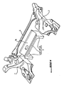
- the cradle shown in Figure 1 comprises two opposite end portions 1, 2 through which the cradle is mounted under the chassis of a motor vehicle and on which are mounted the hubs of the front wheels and elements to change the orientation wheels.
- the cradle also comprises a cross member 3 represented as a molded part.
- the crossmember comprises an elongate profile 31 forming the body of the crossmember and two flanges 32, 33 disposed at the ends of the elongate profile 31.
- the flanges 32, 33 are oriented substantially perpendicular to the longitudinal extent of the elongate section 31 and in the same direction.
- the cross member 3 has a substantially U-shaped, seen perpendicularly to the longitudinal extent of the body 31 of the cross.
- the flanges 32, 33 are provided with through holes for introducing screws to penetrate the parts of the cradle. end 1, 2.
- the body 31 of the crosspiece 3 has a cylindrical recess 34 along its entire length.
- This cylindrical depression 34 is intended to receive elements such as, for example, an electric steering actuator intended to act on a traditional rack of the direction of the motor vehicle.
- the cross member 3 is connected to the end portions 1, 2 according to one or other of the two positions shown in FIGS. 2 and 3. According to the first position (FIG. 2), the flanges 32, 33 extend vertically. downwards when a vehicle element such as, for example, the pipes of an engine exhaust driving the vehicles, is intended to pass below the cradle.
- a vehicle element such as, for example, the pipes of an engine exhaust driving the vehicles
- the flanges 32, 33 extend vertically upwards when the cradle is mounted under the chassis of the motor vehicle.
- This second position is intended for the case where a vehicle element such as, for example, the tubing of the exhaust, is intended to pass over the cradle.
- the modular cradle according to the invention can receive, like the cradles used before the invention, means 5 for changing the direction of the wheels, for example a traditional rack driven by mechanical means also traditional or a hydraulic actuator or electrical steering respectively remote motor or concentric motor.
Landscapes
- Engineering & Computer Science (AREA)
- Chemical & Material Sciences (AREA)
- Combustion & Propulsion (AREA)
- Transportation (AREA)
- Mechanical Engineering (AREA)
- Body Structure For Vehicles (AREA)
- Arrangement Or Mounting Of Propulsion Units For Vehicles (AREA)
- Motor Or Generator Frames (AREA)
- Cooling, Air Intake And Gas Exhaust, And Fuel Tank Arrangements In Propulsion Units (AREA)
- Butt Welding And Welding Of Specific Article (AREA)
Abstract
Description
L'invention concerne un berceau pour un train d'un véhicule automobile, ainsi qu'un véhicule automobile équipé d'un tel berceau.The invention relates to a cradle for a train of a motor vehicle, and a motor vehicle equipped with such a cradle.
Les véhicules automobiles à traction avant ont un train avant comportant un berceau servant d'une part au montage du train avant sous le châssis du véhicule automobile et d'autre part à la fixation des roues avant et des éléments nécessaires pour varier l'orientation des roues avant. Les véhicules à traction arrière ont en plus du train avant avec berceau également un train arrière avec berceau pour monter le train arrière sous le châssis.Front-wheel drive motor vehicles have a front axle comprising a cradle serving firstly to mount the front axle under the chassis of the motor vehicle and secondly to fix the front wheels and the elements necessary to vary the orientation of the front wheels. front wheels. Rear-wheel drive vehicles also have a cradle-mounted front axle and a cradle-mounted rear axle to mount the rear axle under the chassis.
Lorsque le moteur de ce véhicule est situé à l'avant du véhicule, il se pose le problème de devoir organiser une sorte de noeud de croisement formé par des éléments du véhicule tels que la ou les tubulures d'échappement du moteur et, en cas de traction arrière, l'arbre de transmission, et par le berceau et les différents éléments nécessaires pour la variation de l'orientation des roues dans la mesure ou ces éléments sont montés sur le berceau et/ou en liaison avec les roues.When the engine of this vehicle is located at the front of the vehicle, there is the problem of having to organize a sort of crossover node formed by vehicle elements such as the exhaust pipe or the engine and, in case rear traction, the transmission shaft, and the cradle and the various elements necessary for the variation of the orientation of the wheels to the extent that these elements are mounted on the cradle and / or in connection with the wheels.
Les éléments nécessaires pour la variation de l'orientation des roues avant sont essentiellement la crémaillère de direction et le mécanisme qui agit directement sur la crémaillère. Toutefois, lesdits éléments peuvent également comprendre, par exemple, des actionneurs de direction hydrauliques ou électriques.The necessary elements for the variation of the orientation of the front wheels are essentially the steering rack and the mechanism that acts directly on the rack. However, said elements may also include, for example, hydraulic or electric steering actuators.
Par ailleurs, la disposition des tubulures d'échappement varie selon le type de moteur : pour les moteurs à échappement vers l'arrière, les tubulures passent généralement au dessus du berceau, et pour les moteurs à échappement vers l'avant, ils passent sous le berceau.In addition, the arrangement of the exhaust pipes varies according to the type of engine: for the engines with exhaust at the rear, the pipes generally pass over the cradle, and for the engines with exhaust at the front, they pass under the cradle.
La grande variété de trains avant et arrières nécessaire pour équiper les différents modèles de véhicules automobiles et la complexité du noeud de croisement décrit ci-avant, augmentée par le fait que les moteurs de ces véhicules sont équipés avec des échappements dont les tubulures passent soit au-dessus, soit par en dessous du berceau du ou des trains du véhicule, ont pour conséquence une très grande variété de berceaux.The wide variety of front and rear trains needed to equip the various models of motor vehicles and the complexity of the knot of crossing described above, increased by the fact that the engines of these vehicles are equipped with exhausts whose tubings pass either above or below the cradle of the train or trains of the vehicle, result in a great variety cradles.
Un exemple de la technique antérieure est divulgué par le document
Le but de l'invention est de proposer un berceau conçu de manière à réduire la diversité nécessaire de types de berceaux.The object of the invention is to provide a cradle designed to reduce the necessary diversity of types of cradles.
Le but de l'invention est atteint avec un berceau pour un train d'un véhicule automobile ayant un châssis, qui a deux parties d'extrémité opposées dont chacune sert au moins au montage du berceau sous le châssis, et une partie transversale.The object of the invention is achieved with a cradle for a train of a motor vehicle having a frame, which has two opposite end portions each of which serves at least for mounting the cradle under the frame, and a transverse portion.
Selon l'invention, la partie transversale est constituée par une traverse distincte ayant un corps avec deux extrémités opposées pourvues de brides par lesquelles la traverse est montée respectivement sur l'une et sur l'autre de deux pièces formant les parties d'extrémité du berceau, et qui forment un angle avec l'étendue longitudinale de la traverse.According to the invention, the transverse portion is constituted by a separate cross member having a body with two opposite ends provided with flanges through which the cross member is mounted respectively on one and the other of two parts forming the end portions of the cradle, and which form an angle with the longitudinal extent of the crossbar.
L'angle que les brides forment avec l'étendue longitudinale de la traverse peut être un angle droit, mais aussi un angle obtus, par exemple un angle de l'ordre de 130°.The angle that the flanges form with the longitudinal extent of the crossbar may be a right angle, but also an obtuse angle, for example an angle of the order of 130 °.
Grâce à cette disposition selon l'invention, la traverse définit un passage pour un élément du véhicule pouvant passer au-dessus ou en dessous de la traverse, selon la position d'assemblage de la traverse.With this arrangement according to the invention, the cross member defines a passage for a vehicle element that can pass above or below the cross member, depending on the assembly position of the cross member.
L'avantage du berceau selon l'invention par rapport aux berceaux antérieurs repose sur le fait d'être un berceau modulaire. Il est constitué essentiellement par trois pièces dont deux pièces, les deux pièces formant les parties d'extrémités du berceau, peuvent être conçues de manière à être utilisables pour plusieurs types de berceaux. La troisième pièce du berceau selon l'invention, la partie transversale, est par contre une pièce spécifique pour un nombre réduit de types de berceaux, la réduction venant du fait qu'elle peut être montée dans deux positions différentes permettant ainsi à un élément du véhicule, tel que par exemple un échappement, de passer respectivement au-dessus ou en dessous du berceau, selon la position d'assemblage de la traverse.The advantage of the cradle according to the invention compared to previous cradles is based on being a modular cradle. It consists essentially of three parts including two parts, the two parts forming the end portions of the cradle, can be designed to be used for several types of cradles. The third part of the cradle according to the invention, the transverse part, is against a specific piece for a reduced number of types of cradles, the reduction from the fact that it can be mounted in two different positions thus allowing a vehicle element, such as for example an exhaust, to pass respectively above or below cradle, depending on the assembly position of the crossbar.
Grâce à la modularité du berceau de l'invention, on peut combiner maintenant des pièces d'extrémité "multi types" (dans une situation idéale : des pièces d'extrémité standards) avec des traverses individuelles pouvant néanmoins être montées dans deux positions différentes, et réduire ainsi fortement la diversité des berceaux.Thanks to the modularity of the cradle of the invention, it is now possible to combine "multi-type" end pieces (in an ideal situation: standard end pieces) with individual crosspieces that can nevertheless be mounted in two different positions, and greatly reduce the diversity of cradles.
Pour pouvoir définir un passage suffisamment grand, la traverse est formée par un profilé allongé pourvu, à chacune de ses deux extrémités, d'une bride formant un angle avec l'étendue longitudinale de la traverse. Les deux brides s'étendent du même côté de la traverse.To define a sufficiently large passage, the cross is formed by an elongate section provided at each of its two ends, a flange forming an angle with the longitudinal extent of the cross. The two flanges extend on the same side of the crossbar.
La traverse est réalisée soit sous la forme d'une pièce moulée, soit sous la forme d'une pièce mécano-soudée. Pour former le berceau, la traverse et les pièces formant les parties d'extrémité du berceau sont liées entre elles soit par soudage avec un cordon de soudage à chaque extrémité de la traverse, soit par une liaison vissée.The crossbar is made either in the form of a molded part or in the form of a welded part. To form the cradle, the cross member and the parts forming the end portions of the cradle are interconnected either by welding with a welding bead at each end of the crossbar, or by a screw connection.
Le but de l'invention est également atteint avec un véhicule automobile avec un train avant et un train arrière, au moins un des deux trains comprenant un berceau tel que celui décrit ci-avant.The object of the invention is also achieved with a motor vehicle with a front axle and a rear axle, at least one of the two trains comprising a cradle such as that described above.
En effet, le berceau selon l'invention n'est pas réservé au train avant d'un véhicule. Au contraire, l'invention peut très bien s'appliquer au train avant d'un véhicule à propulsion arrière ou à propulsion 4X4 ; on peut très bien imaginer un véhicule ayant une traction avant avec un moteur transversal et les tubulures d'échappement sous le berceau et donc la traverse en position haute. De même, on peut imaginer un véhicule à propulsion arrière ou à 4X4 avec un moteur longitudinal et la traverse en position basse pour loger la transmission longitudinale.Indeed, the cradle according to the invention is not reserved for the front train of a vehicle. On the contrary, the invention can very well be applied to the front axle of a rear-wheel drive vehicle or 4X4 propulsion; one can very well imagine a vehicle having a front wheel drive with a transverse engine and the exhaust pipes under the cradle and therefore the crossbar in high position. Similarly, one can imagine a rear-wheel drive vehicle or 4X4 with a longitudinal engine and the crossbar in the low position to accommodate the longitudinal transmission.
D'autres caractéristiques et avantages de l'invention ressortiront de la description ci-après d'un mode de réalisation du berceau, la description étant faite en référence aux dessins. Dans ces dessins :
- La figure 1 montre, en une vue éclatée, un berceau selon l'invention,
- La figure 2 montre le berceau selon l'invention dans une configuration permettant à un échappement de passer par en dessous du berceau ; et
- La figure 3 montre le berceau de l'invention dans une configuration permettant à un échappement de passer au-dessus du berceau.
- FIG. 1 shows, in an exploded view, a cradle according to the invention,
- Figure 2 shows the cradle according to the invention in a configuration allowing an escapement to pass from below the cradle; and
- Figure 3 shows the cradle of the invention in a configuration allowing an escapement to pass over the cradle.
Le berceau représenté sur la figure 1 comprend deux parties d'extrémité opposées 1, 2 par lesquelles le berceau est monté sous le châssis d'un véhicule automobile et sur lesquelles sont montés les moyeux des roues avant et des éléments permettant de changer l'orientation des roues.The cradle shown in Figure 1 comprises two
Le berceau comprend également une traverse 3 représentée comme une pièce moulée. La traverse comprend un profilé allongé 31 formant le corps de la traverse et deux brides 32, 33 disposées aux extrémités du profilé allongé 31. Les brides 32, 33 sont orientées sensiblement perpendiculairement par rapport à l'étendue longitudinale du profilé allongé 31 et dans la même direction. Ainsi, la traverse 3 présente sensiblement une forme en U, vu perpendiculairement par rapport à l'étendue longitudinale du corps 31 de la traverse.The cradle also comprises a
Lorsque les deux pièces 1, 2 formant les parties d'extrémité du berceau, sont assemblées avec la traverse 3 par vissage, les brides 32, 33 sont pourvues d'orifices traversant permettant d'y introduire des vis destinées à pénétrer dans les pièces d'extrémité 1, 2.When the two
Le corps 31 de la traverse 3 présente un enfoncement cylindrique 34 sur toute sa longueur. Cet enfoncement cylindrique 34 est destiné à recevoir des éléments tels que, par exemple, un actionneur de direction électrique destiné à agir sur une crémaillère traditionnelle de la direction du véhicule automobile.The
La traverse 3 est reliée aux parties d'extrémité 1, 2 selon l'une ou l'autre des deux positions représentées sur les figures 2 et 3. Selon la première position (figure 2), les brides 32, 33 s'étendent verticalement vers le bas lorsqu'un élément de véhicule tel que, par exemple, les tubulures d'un échappement du moteur entraînant les véhicules, est destiné à passer en dessous du berceau.The
Selon la seconde position de montage (figure 3), les brides 32, 33 s'étendent verticalement vers le haut lorsque le berceau est monté sous le châssis du véhicule automobile. Cette seconde position est destinée au cas où un élément de véhicule tel que, par exemple, la tubulure de l'échappement, est destinée à passer au-dessus du berceau.According to the second mounting position (Figure 3), the
Quelque soit la position d'assemblage de la traverse 3 du berceau, le berceau modulable selon l'invention peut recevoir, comme les berceaux utilisés avant l'invention, des moyens 5 permettant de changer la direction des roues, par exemple une crémaillère traditionnelle entraînée par des moyens mécaniques également traditionnels ou un actionneur hydraulique ou électrique de direction respectivement à moteur déporté ou à moteur concentrique.Whatever the assembly position of the
Sur les figures 2 et 3, l'emplacement de ce qui est appelé dans le cas de la présente description de manière générale un élément de véhicule pouvant passer au-dessus ou en dessous de la traverse, par exemple une tubulure d'un échappement, est indiqué en pointillés. Dans l'agencement représenté sur la figure 2, la tubulure d'échappement passe en dessous du berceau 3. Et dans l'agencement représenté sur la figure 3, la tubulure d'échappement passe au-dessus du berceau et, plus précisément, au-dessus de la crémaillère 5.In Figures 2 and 3, the location of what is called in the case of the present description generally a vehicle element that can pass above or below the cross member, for example a pipe of an exhaust, is indicated in dotted lines. In the arrangement shown in Figure 2, the exhaust pipe passes below the
Claims (8)
- Cradle for an axle system of a motor vehicle having a chassis, the cradle having two opposite end parts (1, 2), each of which is used at least for assembly of the cradle under the chassis, and a transverse part (3) made up of a separate cross-member (3) having a body (31) with two opposite ends provided with flanges (32, 33) through which it is mounted one both of the two parts (1, 2) forming the end parts of the cradle, respectively, characterized in that the flanges (32, 33) form an angle with the longitudinal extent of the cross-member, such that the cross-member (3) defines a passage for an element of the vehicle able to pass above or below the cross-member, according to the assembly position of the cross-member.
- Cradle according to claim 1, characterized in that the cross-member is formed by an elongated profile (31) provided, at each of its two ends, with a flange (32, 33) oriented substantially perpendicularly, the two flanges being oriented in the same direction.
- Cradle according to claim 1 or 2, characterized in that the cross-member (3) is a specific part for one type of chassis, while the parts (1, 2) forming the end parts of the cradle are usable for different types of chassis.
- Cradle according to any of claims 1 to 3, characterized in that the cross-member (3) and the parts (1, 2) forming the end parts of the cradle are connected to each other by welding.
- Cradle according to any of claims 1 to 3, characterized in that the cross-section (3) and the parts (1, 2) forming the end parts of the cradle are connected to each other by a screwed connection.
- Cradle according to one of claims 1 to 5, characterized in that at least the cross-member (3) is a molded part.
- Cradle according to any of claims 1 to 5, characterized in that at least the cross-member (3) is a mechanically welded part.
- Motor vehicle with a front axle and a rear axle, characterized in that at least one of the two axle systems comprises a cradle according to any of claims 1 to 7.
Applications Claiming Priority (2)
| Application Number | Priority Date | Filing Date | Title |
|---|---|---|---|
| FR0401483A FR2866305B1 (en) | 2004-02-13 | 2004-02-13 | MODULAR CRADLE FOR A MOTOR VEHICLE AND MOTOR VEHICLE COMPRISING SUCH A CRADLE |
| FR0401483 | 2004-02-13 |
Publications (2)
| Publication Number | Publication Date |
|---|---|
| EP1564112A1 EP1564112A1 (en) | 2005-08-17 |
| EP1564112B1 true EP1564112B1 (en) | 2007-12-12 |
Family
ID=34685022
Family Applications (1)
| Application Number | Title | Priority Date | Filing Date |
|---|---|---|---|
| EP05290034A Expired - Lifetime EP1564112B1 (en) | 2004-02-13 | 2005-01-06 | Versatile subframe for automobile, and automobile equipped with such a subframe |
Country Status (4)
| Country | Link |
|---|---|
| EP (1) | EP1564112B1 (en) |
| AT (1) | ATE380739T1 (en) |
| DE (1) | DE602005003685T2 (en) |
| FR (1) | FR2866305B1 (en) |
Families Citing this family (7)
| Publication number | Priority date | Publication date | Assignee | Title |
|---|---|---|---|---|
| FR2949996B1 (en) | 2009-09-11 | 2012-10-05 | Peugeot Citroen Automobiles Sa | MODULAR AXLE FOR A VEHICLE RAILWAY, IN PARTICULAR FOR A MOTOR VEHICLE |
| FR2959450B1 (en) * | 2010-04-29 | 2013-03-08 | Peugeot Citroen Automobiles Sa | SUSPENSION SUPPORT DEVICE |
| DE102011086338B4 (en) * | 2011-11-15 | 2016-11-10 | Bayerische Motoren Werke Aktiengesellschaft | Axle carrier for two-lane vehicles |
| DE102012103125A1 (en) * | 2012-04-12 | 2013-10-17 | Dr. Ing. H.C. F. Porsche Aktiengesellschaft | Carrier structure for drive axle arrangement of motor vehicle e.g. car, has cross beam and auxiliary frame that are connected with vehicle chassis over bearing points and provided with bearing elements to receive vehicle assemblies |
| DE102015224894A1 (en) | 2015-12-10 | 2017-06-14 | Volkswagen Aktiengesellschaft | Hinterachshilfsrahmen and motor vehicle with such a Hinterachshilfsrahmen |
| DE102018007435A1 (en) | 2018-09-20 | 2019-02-28 | Daimler Ag | Domstrebenanordnung for a motor vehicle |
| FR3089937B1 (en) * | 2018-12-14 | 2021-02-19 | Renault Sas | CRADLE STRUCTURE PROVIDED WITH A CABLE OR PIPE PASSAGE |
Family Cites Families (5)
| Publication number | Priority date | Publication date | Assignee | Title |
|---|---|---|---|---|
| EP0441818B1 (en) * | 1988-11-05 | 1993-08-11 | Volkswagen Aktiengesellschaft | A modular unit for releasable connection to the structure of a motor vehicle |
| DE4129538C2 (en) * | 1991-09-05 | 1993-11-18 | Porsche Ag | Subframe for a motor vehicle |
| IT232382Y1 (en) * | 1994-04-22 | 1999-12-17 | Fiat Auto Spa | EQUIPMENT FOR THE ASSEMBLY OF A MULTIPLE OF AUXILIARY FRAMES FOR CARS. |
| US6398262B1 (en) * | 2000-09-26 | 2002-06-04 | Dana Corporation | Modular subframe assembly for a motor vehicle |
| US6733021B1 (en) * | 2001-10-26 | 2004-05-11 | Dana Corporation | Vehicle subframe mounting |
-
2004
- 2004-02-13 FR FR0401483A patent/FR2866305B1/en not_active Expired - Fee Related
-
2005
- 2005-01-06 AT AT05290034T patent/ATE380739T1/en not_active IP Right Cessation
- 2005-01-06 DE DE602005003685T patent/DE602005003685T2/en not_active Expired - Lifetime
- 2005-01-06 EP EP05290034A patent/EP1564112B1/en not_active Expired - Lifetime
Also Published As
| Publication number | Publication date |
|---|---|
| EP1564112A1 (en) | 2005-08-17 |
| FR2866305B1 (en) | 2006-05-19 |
| ATE380739T1 (en) | 2007-12-15 |
| DE602005003685T2 (en) | 2009-01-02 |
| FR2866305A1 (en) | 2005-08-19 |
| DE602005003685D1 (en) | 2008-01-24 |
Similar Documents
| Publication | Publication Date | Title |
|---|---|---|
| WO2008141676A1 (en) | Steering mechanism, particularly for short vehicles | |
| FR2673589A1 (en) | STEERING COLUMN TUBE FOR MOTOR VEHICLE. | |
| FR2909633A1 (en) | VEHICLE WITH A CABIN | |
| FR2866305A1 (en) | MODULAR CRADLE FOR A MOTOR VEHICLE AND MOTOR VEHICLE COMPRISING SUCH A CRADLE | |
| FR2935672A1 (en) | Rear steering suspension arm for rear axle of motor vehicle, has turning actuator driving steering wheel swivel by gear comprising endless screw, where actuator has toothed sector centered on steering wheel swivel | |
| EP2188157A2 (en) | Shock impactor for an automobile powertrain | |
| EP1529720B2 (en) | Structural beam for vehicle | |
| FR2774057A1 (en) | SUPPORT FRAME FOR HOUSING FUNCTIONAL MODULES OF A MOTOR VEHICLE | |
| EP2342120B1 (en) | Dashboard crossbar assembly for an automobile, and corresponding dashboard device, vehicle, and manufacturing method | |
| EP1904316B1 (en) | Motor vehicle flexible axle, comprising a cross bracing with open cross-section whereof the flanks include rectilinear edges, cross bracing and corresponding motor vehicle | |
| EP1054173B1 (en) | Connecting rod for limiting relative movement between two rigid elements | |
| EP2019023A1 (en) | Steering rear end for automobile, comprising a deformable wheel pivot | |
| FR2833541A1 (en) | ARRANGEMENT FOR INSTRUMENTS OF A MOTOR VEHICLE DASHBOARD | |
| FR2748714A1 (en) | Scooter passenger footrest fixing structure | |
| FR2816272A1 (en) | FRONT PANEL WITH SHIELD FOR MOTOR VEHICLE | |
| EP1542897A1 (en) | Motor vehicle | |
| EP1182092A1 (en) | Arrangement for mounting an electrical unit in a vehicle | |
| FR2753931A1 (en) | Vehicle wheel triangular suspension | |
| FR2892790A1 (en) | Shift device for gear wheel changing transmission has shift rod connector in form of two deformed sheet halves fixed to each other and to base body | |
| EP4098498B1 (en) | Device for coupling a trailer to a tractor vehicle provided with a structure with hinged connection | |
| FR2904070A1 (en) | Driving and driven shafts connecting homocinetic joint for motor vehicle, has coupling unit with connection jaws connected to cardan jaws, and filtering unit filtering vibrations between connection jaws | |
| EP3650325A1 (en) | Transport vehicle | |
| WO2011030074A1 (en) | Tubular structure for forming especially an axle of the running gear of a motor vehicle | |
| EP1510445A1 (en) | Body structure for an automobile | |
| FR2821020A1 (en) | AXLE FOR VEHICLE AND APPLICATION TO MULTIPLE AXLES |
Legal Events
| Date | Code | Title | Description |
|---|---|---|---|
| PUAI | Public reference made under article 153(3) epc to a published international application that has entered the european phase |
Free format text: ORIGINAL CODE: 0009012 |
|
| AK | Designated contracting states |
Kind code of ref document: A1 Designated state(s): AT BE BG CH CY CZ DE DK EE ES FI FR GB GR HU IE IS IT LI LT LU MC NL PL PT RO SE SI SK TR |
|
| AX | Request for extension of the european patent |
Extension state: AL BA HR LV MK YU |
|
| RIN1 | Information on inventor provided before grant (corrected) |
Inventor name: MALLET, CEDRIC Inventor name: DAUBANNAY, ALEXANDRE Inventor name: JANSSENS, JEAN-BAPTISTE |
|
| 17P | Request for examination filed |
Effective date: 20051222 |
|
| AKX | Designation fees paid |
Designated state(s): AT BE BG CH CY CZ DE DK EE ES FI FR GB GR HU IE IS IT LI LT LU MC NL PL PT RO SE SI SK TR |
|
| GRAP | Despatch of communication of intention to grant a patent |
Free format text: ORIGINAL CODE: EPIDOSNIGR1 |
|
| GRAS | Grant fee paid |
Free format text: ORIGINAL CODE: EPIDOSNIGR3 |
|
| GRAA | (expected) grant |
Free format text: ORIGINAL CODE: 0009210 |
|
| AK | Designated contracting states |
Kind code of ref document: B1 Designated state(s): AT BE BG CH CY CZ DE DK EE ES FI FR GB GR HU IE IS IT LI LT LU MC NL PL PT RO SE SI SK TR |
|
| REG | Reference to a national code |
Ref country code: GB Ref legal event code: FG4D Free format text: NOT ENGLISH |
|
| REG | Reference to a national code |
Ref country code: CH Ref legal event code: EP |
|
| REG | Reference to a national code |
Ref country code: IE Ref legal event code: FG4D Free format text: LANGUAGE OF EP DOCUMENT: FRENCH |
|
| REF | Corresponds to: |
Ref document number: 602005003685 Country of ref document: DE Date of ref document: 20080124 Kind code of ref document: P |
|
| GBT | Gb: translation of ep patent filed (gb section 77(6)(a)/1977) |
Effective date: 20080221 |
|
| PG25 | Lapsed in a contracting state [announced via postgrant information from national office to epo] |
Ref country code: SE Free format text: LAPSE BECAUSE OF FAILURE TO SUBMIT A TRANSLATION OF THE DESCRIPTION OR TO PAY THE FEE WITHIN THE PRESCRIBED TIME-LIMIT Effective date: 20080312 |
|
| PG25 | Lapsed in a contracting state [announced via postgrant information from national office to epo] |
Ref country code: PL Free format text: LAPSE BECAUSE OF FAILURE TO SUBMIT A TRANSLATION OF THE DESCRIPTION OR TO PAY THE FEE WITHIN THE PRESCRIBED TIME-LIMIT Effective date: 20071212 Ref country code: SI Free format text: LAPSE BECAUSE OF FAILURE TO SUBMIT A TRANSLATION OF THE DESCRIPTION OR TO PAY THE FEE WITHIN THE PRESCRIBED TIME-LIMIT Effective date: 20071212 Ref country code: FI Free format text: LAPSE BECAUSE OF FAILURE TO SUBMIT A TRANSLATION OF THE DESCRIPTION OR TO PAY THE FEE WITHIN THE PRESCRIBED TIME-LIMIT Effective date: 20071212 Ref country code: LT Free format text: LAPSE BECAUSE OF FAILURE TO SUBMIT A TRANSLATION OF THE DESCRIPTION OR TO PAY THE FEE WITHIN THE PRESCRIBED TIME-LIMIT Effective date: 20071212 Ref country code: NL Free format text: LAPSE BECAUSE OF FAILURE TO SUBMIT A TRANSLATION OF THE DESCRIPTION OR TO PAY THE FEE WITHIN THE PRESCRIBED TIME-LIMIT Effective date: 20071212 |
|
| NLV1 | Nl: lapsed or annulled due to failure to fulfill the requirements of art. 29p and 29m of the patents act | ||
| PG25 | Lapsed in a contracting state [announced via postgrant information from national office to epo] |
Ref country code: AT Free format text: LAPSE BECAUSE OF FAILURE TO SUBMIT A TRANSLATION OF THE DESCRIPTION OR TO PAY THE FEE WITHIN THE PRESCRIBED TIME-LIMIT Effective date: 20071212 |
|
| BERE | Be: lapsed |
Owner name: PEUGEOT CITROEN AUTOMOBILES S.A. Effective date: 20080131 |
|
| PG25 | Lapsed in a contracting state [announced via postgrant information from national office to epo] |
Ref country code: ES Free format text: LAPSE BECAUSE OF FAILURE TO SUBMIT A TRANSLATION OF THE DESCRIPTION OR TO PAY THE FEE WITHIN THE PRESCRIBED TIME-LIMIT Effective date: 20080323 Ref country code: IS Free format text: LAPSE BECAUSE OF FAILURE TO SUBMIT A TRANSLATION OF THE DESCRIPTION OR TO PAY THE FEE WITHIN THE PRESCRIBED TIME-LIMIT Effective date: 20080412 Ref country code: CZ Free format text: LAPSE BECAUSE OF FAILURE TO SUBMIT A TRANSLATION OF THE DESCRIPTION OR TO PAY THE FEE WITHIN THE PRESCRIBED TIME-LIMIT Effective date: 20071212 |
|
| PG25 | Lapsed in a contracting state [announced via postgrant information from national office to epo] |
Ref country code: SK Free format text: LAPSE BECAUSE OF FAILURE TO SUBMIT A TRANSLATION OF THE DESCRIPTION OR TO PAY THE FEE WITHIN THE PRESCRIBED TIME-LIMIT Effective date: 20071212 Ref country code: RO Free format text: LAPSE BECAUSE OF FAILURE TO SUBMIT A TRANSLATION OF THE DESCRIPTION OR TO PAY THE FEE WITHIN THE PRESCRIBED TIME-LIMIT Effective date: 20071212 Ref country code: MC Free format text: LAPSE BECAUSE OF NON-PAYMENT OF DUE FEES Effective date: 20080131 |
|
| PG25 | Lapsed in a contracting state [announced via postgrant information from national office to epo] |
Ref country code: PT Free format text: LAPSE BECAUSE OF FAILURE TO SUBMIT A TRANSLATION OF THE DESCRIPTION OR TO PAY THE FEE WITHIN THE PRESCRIBED TIME-LIMIT Effective date: 20080512 |
|
| REG | Reference to a national code |
Ref country code: IE Ref legal event code: FD4D |
|
| PLBE | No opposition filed within time limit |
Free format text: ORIGINAL CODE: 0009261 |
|
| STAA | Information on the status of an ep patent application or granted ep patent |
Free format text: STATUS: NO OPPOSITION FILED WITHIN TIME LIMIT |
|
| PG25 | Lapsed in a contracting state [announced via postgrant information from national office to epo] |
Ref country code: DK Free format text: LAPSE BECAUSE OF FAILURE TO SUBMIT A TRANSLATION OF THE DESCRIPTION OR TO PAY THE FEE WITHIN THE PRESCRIBED TIME-LIMIT Effective date: 20071212 Ref country code: IE Free format text: LAPSE BECAUSE OF FAILURE TO SUBMIT A TRANSLATION OF THE DESCRIPTION OR TO PAY THE FEE WITHIN THE PRESCRIBED TIME-LIMIT Effective date: 20071212 |
|
| 26N | No opposition filed |
Effective date: 20080915 |
|
| PG25 | Lapsed in a contracting state [announced via postgrant information from national office to epo] |
Ref country code: GR Free format text: LAPSE BECAUSE OF FAILURE TO SUBMIT A TRANSLATION OF THE DESCRIPTION OR TO PAY THE FEE WITHIN THE PRESCRIBED TIME-LIMIT Effective date: 20080313 Ref country code: EE Free format text: LAPSE BECAUSE OF FAILURE TO SUBMIT A TRANSLATION OF THE DESCRIPTION OR TO PAY THE FEE WITHIN THE PRESCRIBED TIME-LIMIT Effective date: 20071212 |
|
| PG25 | Lapsed in a contracting state [announced via postgrant information from national office to epo] |
Ref country code: BE Free format text: LAPSE BECAUSE OF NON-PAYMENT OF DUE FEES Effective date: 20080131 |
|
| PG25 | Lapsed in a contracting state [announced via postgrant information from national office to epo] |
Ref country code: BG Free format text: LAPSE BECAUSE OF FAILURE TO SUBMIT A TRANSLATION OF THE DESCRIPTION OR TO PAY THE FEE WITHIN THE PRESCRIBED TIME-LIMIT Effective date: 20080312 |
|
| PG25 | Lapsed in a contracting state [announced via postgrant information from national office to epo] |
Ref country code: CY Free format text: LAPSE BECAUSE OF FAILURE TO SUBMIT A TRANSLATION OF THE DESCRIPTION OR TO PAY THE FEE WITHIN THE PRESCRIBED TIME-LIMIT Effective date: 20071212 |
|
| REG | Reference to a national code |
Ref country code: CH Ref legal event code: PL |
|
| PG25 | Lapsed in a contracting state [announced via postgrant information from national office to epo] |
Ref country code: CH Free format text: LAPSE BECAUSE OF NON-PAYMENT OF DUE FEES Effective date: 20090131 Ref country code: LI Free format text: LAPSE BECAUSE OF NON-PAYMENT OF DUE FEES Effective date: 20090131 |
|
| PG25 | Lapsed in a contracting state [announced via postgrant information from national office to epo] |
Ref country code: LU Free format text: LAPSE BECAUSE OF NON-PAYMENT OF DUE FEES Effective date: 20080106 Ref country code: HU Free format text: LAPSE BECAUSE OF FAILURE TO SUBMIT A TRANSLATION OF THE DESCRIPTION OR TO PAY THE FEE WITHIN THE PRESCRIBED TIME-LIMIT Effective date: 20080613 |
|
| PG25 | Lapsed in a contracting state [announced via postgrant information from national office to epo] |
Ref country code: TR Free format text: LAPSE BECAUSE OF FAILURE TO SUBMIT A TRANSLATION OF THE DESCRIPTION OR TO PAY THE FEE WITHIN THE PRESCRIBED TIME-LIMIT Effective date: 20071212 |
|
| PG25 | Lapsed in a contracting state [announced via postgrant information from national office to epo] |
Ref country code: IT Free format text: LAPSE BECAUSE OF NON-PAYMENT OF DUE FEES Effective date: 20080131 |
|
| PGFP | Annual fee paid to national office [announced via postgrant information from national office to epo] |
Ref country code: GB Payment date: 20121224 Year of fee payment: 9 |
|
| PGFP | Annual fee paid to national office [announced via postgrant information from national office to epo] |
Ref country code: FR Payment date: 20130305 Year of fee payment: 9 Ref country code: DE Payment date: 20121226 Year of fee payment: 9 |
|
| REG | Reference to a national code |
Ref country code: DE Ref legal event code: R119 Ref document number: 602005003685 Country of ref document: DE |
|
| GBPC | Gb: european patent ceased through non-payment of renewal fee |
Effective date: 20140106 |
|
| REG | Reference to a national code |
Ref country code: DE Ref legal event code: R119 Ref document number: 602005003685 Country of ref document: DE Effective date: 20140801 |
|
| PG25 | Lapsed in a contracting state [announced via postgrant information from national office to epo] |
Ref country code: DE Free format text: LAPSE BECAUSE OF NON-PAYMENT OF DUE FEES Effective date: 20140801 |
|
| REG | Reference to a national code |
Ref country code: FR Ref legal event code: ST Effective date: 20140930 |
|
| PG25 | Lapsed in a contracting state [announced via postgrant information from national office to epo] |
Ref country code: FR Free format text: LAPSE BECAUSE OF NON-PAYMENT OF DUE FEES Effective date: 20140131 Ref country code: GB Free format text: LAPSE BECAUSE OF NON-PAYMENT OF DUE FEES Effective date: 20140106 |