EP1564332A2 - Milling machine and method for working the soil - Google Patents
Milling machine and method for working the soil Download PDFInfo
- Publication number
- EP1564332A2 EP1564332A2 EP05002009A EP05002009A EP1564332A2 EP 1564332 A2 EP1564332 A2 EP 1564332A2 EP 05002009 A EP05002009 A EP 05002009A EP 05002009 A EP05002009 A EP 05002009A EP 1564332 A2 EP1564332 A2 EP 1564332A2
- Authority
- EP
- European Patent Office
- Prior art keywords
- channel
- transport
- suction
- milling
- channel section
- Prior art date
- Legal status (The legal status is an assumption and is not a legal conclusion. Google has not performed a legal analysis and makes no representation as to the accuracy of the status listed.)
- Granted
Links
Images

Classifications
-
- E—FIXED CONSTRUCTIONS
- E01—CONSTRUCTION OF ROADS, RAILWAYS, OR BRIDGES
- E01C—CONSTRUCTION OF, OR SURFACES FOR, ROADS, SPORTS GROUNDS, OR THE LIKE; MACHINES OR AUXILIARY TOOLS FOR CONSTRUCTION OR REPAIR
- E01C23/00—Auxiliary devices or arrangements for constructing, repairing, reconditioning, or taking-up road or like surfaces
- E01C23/06—Devices or arrangements for working the finished surface; Devices for repairing or reconditioning the surface of damaged paving; Recycling in place or on the road
- E01C23/08—Devices or arrangements for working the finished surface; Devices for repairing or reconditioning the surface of damaged paving; Recycling in place or on the road for roughening or patterning; for removing the surface down to a predetermined depth high spots or material bonded to the surface, e.g. markings; for maintaining earth roads, clay courts or like surfaces by means of surface working tools, e.g. scarifiers, levelling blades
- E01C23/085—Devices or arrangements for working the finished surface; Devices for repairing or reconditioning the surface of damaged paving; Recycling in place or on the road for roughening or patterning; for removing the surface down to a predetermined depth high spots or material bonded to the surface, e.g. markings; for maintaining earth roads, clay courts or like surfaces by means of surface working tools, e.g. scarifiers, levelling blades using power-driven tools, e.g. vibratory tools
- E01C23/088—Rotary tools, e.g. milling drums
-
- B—PERFORMING OPERATIONS; TRANSPORTING
- B28—WORKING CEMENT, CLAY, OR STONE
- B28D—WORKING STONE OR STONE-LIKE MATERIALS
- B28D7/00—Accessories specially adapted for use with machines or devices of the preceding groups
- B28D7/02—Accessories specially adapted for use with machines or devices of the preceding groups for removing or laying dust, e.g. by spraying liquids; for cooling work
-
- E—FIXED CONSTRUCTIONS
- E01—CONSTRUCTION OF ROADS, RAILWAYS, OR BRIDGES
- E01C—CONSTRUCTION OF, OR SURFACES FOR, ROADS, SPORTS GROUNDS, OR THE LIKE; MACHINES OR AUXILIARY TOOLS FOR CONSTRUCTION OR REPAIR
- E01C2301/00—Machine characteristics, parts or accessories not otherwise provided for
- E01C2301/50—Methods or devices for preventing dust by spraying or sucking
Definitions
- the invention relates to a milling machine for processing ground surfaces, in particular roadways, according to the preamble of claim 1, and a method to dispose of dust generated during milling and steaming on a milling machine according to the preamble of claim 9.
- Such milling machines are self-propelled and are also called street milling machines designated.
- a front loading router according to the preamble of claim 1 is known from DE 102 23 819 A1.
- the well-known road milling machines have a self-propelled Chassis with a chassis consisting of several wheel drives or several crawler drives.
- the chassis carries a machine frame, in which a milling drum transverse to Direction is stored.
- the milling drum is usually of a housing surrounded, in which the pointing in the direction of travel wall as a cover is formed with a passage opening for the milled material. That from the milling drum processed material is taken from a first conveyor belt, that the processed material at the front end of the milling machine transferred to a discharge conveyor for transport to a loading area of a truck in the inclination and is laterally pivotable.
- the one at the back End cyclone separator can only segregate the coarser particles not the respirable particulate matter, so the arrangement of the air outlet arranged at the rear end of the road milling machine too close to the control station is. This causes the dusts and fumes at the rear end of the milling machine blown off near the helm. Furthermore, the fan transports the dust-laden air, allowing high wear to a short life of the blower leads.
- the suction device has a suction channel arranged axial fan, due to the high load with Dusts and sharp-edged particles are subject to severe wear and tear ultimately results in reduced air output and bearing damage.
- the fan blades of the axial fan are due to the impact and the deflection of the high-speed particles supplied strong worn and damaged.
- Aspirating larger particles and small stones are also other parts of the blower mechanically damaged, with at Damage to the fan blades often also imbalances occur in the further operation may lead to bearing damage.
- a repair is disadvantageous that the fan is located in a hard to reach place and therefore a Repair leads to a major business interruption.
- the fan due transport of dusts and sharp particles the fan be designed so that the game between the fan blades and the walls the blower is larger, so that the air performance and efficiency of such a fan for dust and particle laden air is lower.
- the invention has the object underlying, a milling machine of the type mentioned, and a method to dispose of dusts and vapors, with little mechanical Effort and with higher efficiency in the milling process and the Transport process resulting dusts and vapors, especially the respirable Dust, can be sucked off and disposed of while doing the Service life of the suction device can be considerably extended.
- the invention advantageously provides that the suction device a suction fan, a separator for solids and a suction channel which is at the rear in the material transport direction channel section connected to the suction fan downstream of the separator is arranged and that the deposition device, the deposited Solids on the transport device in a front in material transport direction Channel section, or disposed of in a collection and the purified Air blows off to the outside.
- the invention enables a simple construction, in which the construction of a Road milling machine does not basically need to be changed, so also a retrofit existing road milling is possible. Because of the suction fan the suction device is arranged behind the separator, the Suction fan operated on the clean air side, so that the suction fan a higher Life has.
- the invention not only allows a significantly increased Service life of the suction fan, but also a significant improvement the air quality in the environment of the control station.
- the clean air is blown off directly into the open air.
- the secluded Solids can either be on the transport device in the front channel section or disposed of in a collection facility.
- Such a collector may e.g. from an air-permeable dust bag exist, which decreased in business interruptions of the road milling machine can be used to dispose of the separated solids.
- the separating device consists of a filter device and that of the forming in the filter device filter cake on the transport device in the front channel section or in the collecting device is disposable.
- a filter device has the Advantage that these high efficiency in terms of breathable dusts and that the separated solids compacted into a filter cake which is easier to dispose of without disposal
- dusts can be generated to a considerable extent.
- binders e.g. a hydrous one Spray mist to compress even more, so when disposed of at all dusts can no longer arise.
- the filter cake may be removed from the filter device at predetermined time intervals or automatically removed at a predetermined pressure loss. there it is also possible, the filter device only during breaks, e.g. at To clean a tool change, if the filter capacity designed accordingly is. Another way to add the filter cake from the filter device remove, every time you change the front of the road milling machine truck and the associated short-term work break.
- the filter device is then for cleaning, for example, with a vibration or acted upon by a pulse-like counterpressure.
- the front channel section from the rear channel section with release means for the most part Locking an air flow is separated without the transport of the milled off Material is obstructed.
- the separation of the channel into one Front and a rear channel section ensures that the over the Suction duct in the material transport direction extracted dust-laden air only off the rear, dust-laden channel section is sucked, and that no Air flow in the front channel section against the Materialtransportides can arise.
- the division is made by release agents, on the one hand not hinder the transport of the milled material and on the other hand a Prevent air flow against the material transport direction.
- the transport device at least one Has conveyor belt with a conveyor belt, and that sealing means for the Channel out against the conveyor belt and against the housing of the conveyor belt consist of sealing hoods.
- the hoods thus form together with the Conveyor belt or together with the housing of the conveyor belt a closed Channel, so that the milled material, the transport device circumferentially passes completely enclosed. That way you can go along of the duct do not emit dusts or vapors to the outside. Minor gaps in the Channel course are irrelevant, since the channel is under negative pressure, so that contaminated air can not escape at any points of leakage, but at most air is sucked.
- a second front transport means may be the milled material at the end take over the first rear transport device at a transfer point.
- the transfer point between the first and the second transport device circumferentially sealed with flexible sealing means, the at least one of the transport devices are attached. It becomes a consistent one Channel formed, which contains both transport facilities.
- the separating means may consist of a flexible flap, which is the rear channel section the transport device against air inlet against the material transport device closes.
- the negative pressure in the rear channel section reinforces the seal by sucking the flap on the conveyor belt.
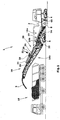
- FIG. 1 A road milling machine 1 for working roadways in the embodiment a front-end loader is shown in FIG. It is understood that the Invention is applicable to other types of milling machines, with at least a transport device 14, 18 are provided.
- the road milling machine 1 is used for milling off ground surfaces, in particular Roads made of asphalt, concrete o. The like.
- the road milling machine 1 has a Chassis with, for example, four crawlers 4 on which the machine frame 2 carries. It is understood that the crawler tracks through wheel drives can be substituted in whole or in part.
- a milling drum 8 mounted, which extends transversely to the direction of travel. The attitude The milling depth is preferably carried out by means of the height adjustment of the chain drives 4.
- the road milling machine 1 shown in Fig. 1 is also called Front loader road milling machine called, as they the milled material in the direction of travel transported forward to a transport vehicle 10.
- a first consisting of a conveyor belt transport device 14 with a conveyor belt 15 in a shaft 9 of the machine frame 2, which extends at an inclination angle in the machine frame 2.
- the first transporting device 14 conveys the milled material 3 the conveyor belt 15 to a second, preferably also a conveyor belt 19th having transporting device 18.
- the second transporting device 18 is adjustable in height via an adjustable inclination angle and can additionally be pivoted laterally by, for example ⁇ 30 °, so that in addition to the Lane of the road milling machine stationary transport vehicles 10 loaded can be.
- the conveyor belts 15, 19 is also the use of in a conveyor arranged screw conveyor possible.
- the milling drum 8 is usually surrounded by a roller box 58 at the facing in the direction of travel wall as a shield 52 with a passage opening 56 is formed for the milled material.
- the milling drum 8 is provided with helically arranged chisel tools, which are arranged so that the milled material 3 to the passage opening 56th is transported in the shield 52.
- Roller box 58 is a close to the milled ground surface final Wall 60 of the roller box 58 provided the milled soil surface peels off so that no fragments of the milled material 3 on the milled soil surface remain.
- the wall 60 is with its lower edge hydraulically pressed against the ground surface to ensure the best possible sealing to achieve.
- On machine frame 2 is designated as a band shoe 50 band protection and Support device mounted height adjustable in a guide.
- the belt shoe 50 takes up the rear end of the first transport device 14.
- the passage opening 56 of the roller box 58 forms a first transfer point 5, at which the milled material from the milling drum 8 on the first conveyor 14th is handed over.
- the control station is located in the embodiment of FIG. 1 above the Milling roller 8, but can as usual in road milling machines in the rear or front portion of the machine frame 2 may be arranged.
- FIGS. 5 and 6 show in detail the first transport device 14.
- the transport device 14 is arranged in a preferably centrally Shaft 9 of the machine frame 2 is fixed and can easily from the belt shoe 50 are dismantled for maintenance purposes and through the shaft 9 therethrough get extended.
- the transport device 14 with the conveyor belt 15 has a hood 22 which together with the upper run 15a of the conveyor belt 15 a channel section 16 a of a channel 16 extending from the roller box 58 to the end of second transport means 18 extends.
- Elastic lips 46 can on the hood brackets 44 on both sides of the Be fastened conveyor belt and the upper run 15 a of the conveyor belt 15 in Touch edge area over the entire length of the upper run 15a.
- the second transport device 18 with a hood 26 be provided.
- the entire channel 16 dustproof and gas-tight be sealed against the environment, even if the sealing of the Front channel section 16b is only really necessary if one more Noteworthy dust formation in the front channel section 16b even detectable is.
- the hood 22 of the first transport device 14 at least one nozzle 23, 23 a, 23 b, to the at least one suction channel 24 is connectable.
- the suction channel 24 of two suction hoses 24a, 24b formed by the nozzle 23a, 23b lead to the inlet side of a filter housing of a filter device 25, preferably in the region of the front channel portion 16b on the hood 26 of the front transport device 18 is placed.
- the filter device 25 is preferably composed of several, e.g. ten filter cartridges 31, preferably are connected in parallel to form a large filter surface.
- the Suction fan 28 is arranged on the output side of the clean air side and is characterized only charged with clean air.
- An exhaust pipe 29 allows to blow off the cleaned exhaust air directly into the open air. Alternatively, the clean air on the front end of the filter device 25 or at the front end of the front Transport device 18 are blown off.
- the suction fan 28 allows a high air flow and thus generates a corresponding high negative pressure in the rear channel section 16a and in the milling drum 8 surrounding roller box 58. The dusts arising during the milling process and vapors are therefore reliable and with high efficiency over the Suction duct 24, 24a, 24b sucked.
- the flaps 36 are provided with slots.
- several Flaps 36 arranged one behind the other to provide an improved air seal between to reach the channel sections 16a, 16b ( Figure 5).
- the preferably consisting of flaps 36 release agent within the channel 16 also elsewhere, e.g. in material transport direction behind the second transfer point 7 in the region of the second transport device 18 may be arranged.
- the rear channel section 16a thus ends at the release means in the material transport device downstream of the transfer point 7 are arranged.
- the conveyor belt 15 is, as best seen in Fig. 7, via support rollers 62,64 out, wherein the upper run 15a has a substantially U-shaped groove forms by the support rollers 64 are inclined accordingly.
- the lower support roller 62 supports the lower run 15b of the conveyor belt 15. As shown in FIGS. 3 and Figure 4 shows, there are 15 webs on the surface of the conveyor belt 17, which improve the entrainment of the milled material 3 on the conveyor belt 15.
- the milled material 3 at the second transfer point 7 into a receiving hopper 35 of the second Passing conveyor 18, whereby the milled material 3 on the Conveyor belt 19 is conveyed to the discharge end and the transport vehicle 10 is disposed of.
- the Filter cake the filter device 25 via a flap 37 in the filter housing 33rd be disposed of (Fig. 5).
- the filter cake in one of a Dust collection bag existing collecting device 39 are filled (Fig. 6), which is attached to an opening of the filter housing 33.
- a flap 37 in the bottom of the filter housing 33rd be provided.
- the transition point at the transfer point 7 is made of flexible mats 30 existing Sealing means enclosed, so that the first transport device 14 and the second transport device 18 in a material transport direction form continuous circumferentially sealed channel 16.
- Filter device 25 is set at intervals selectable by the operator, e.g. during business interruptions, such as Change of the preceding driver Truck 10 or tool change to manual command, e.g. by vibration or by applying a pressure pulse in the counterflow direction cleaned.
- the seated on the filter cartridges 31 filter cake away.
- the filter cake also depending on with increasing operating time of the filter device 25 forming pressure loss, or be automatically cleaned after predetermined time intervals.
- Filter cake removed from the filter cartridges 31 may be due to inclination the bottom of the filter housing 33 to the rear end of the filter housing 33 slip, where, for example, a flap 37 and the receiving hopper 35 can be disposed of on the front transport device 18. That's it also possible to compress the filter cake additionally by a spray and cohesion of the deposited particles through the spray increase.
- the filter cake behind the release agents the front transport device 18 abandoned.
- suction hoses 24a, 24b of the suction channel 24 occur, as shown in FIG. 2, from two opposite sides in the filter housing 33, wherein the Filter cartridges 31 from the outside charged with the dust and vapor laden air become.
Landscapes
- Engineering & Computer Science (AREA)
- Mechanical Engineering (AREA)
- Mining & Mineral Resources (AREA)
- Architecture (AREA)
- Civil Engineering (AREA)
- Structural Engineering (AREA)
- Road Repair (AREA)
- Crushing And Grinding (AREA)
Abstract
Bei einer Fräsmaschine (1) zum Bearbeiten von Bodenoberflächen, mit einem Maschinenrahmen (2), einer an dem Maschinenrahmen (2) gelagerten Fräswalze (8), mindestens einer an dem Maschinenrahmen (2) angeordneten Transporteinrichtung (14, 18), die das abgefräste Material (3) von der Fräswalze (8) übernimmt, sowie mit einer Absaugeinrichtung (20) für die mit Stäuben und Dämpfen verunreinigte Luft, wobei das abgefräste Material (3) auf der mindestens einen Transporteinrichtung (14, 18) von einem Kanal (16) umschlossen ist, die Absaugeinrichtung (20) an einen in Materialtransportrichtung hinteren Kanalabschnitt (16a) des Kanals (16) angeschlossen ist und die beim Fräsen verunreinigte Luft an der Fräswalze (8) und in dem vorderen Kanalabschnitt (16) im wesentlichen in Materialtransportrichtung absaugt, ist vorgesehen, dass die Absaugeinrichtung (20) aus einem Sauggebläse (28), einer Abscheideeinrichtung für Feststoffe und einem Absaugkanal (24) besteht, der an dem hinteren Kanalabschnitt (16a) angeschlossen ist, dass das Sauggebläse (28) stromabwärts der Abscheideeinrichtung angeordnet ist, und dass die Absaugeinrichtung die abgeschiedenen Feststoffe auf die Transporteinrichtung (18) in einem in Materialtransportrichtung vorderen Kanalabschnitt (16b) oder in eine Sammeleinrichtung entsorgt und das Sauggebläse (28) die gereinigte Luft in die Umgebung abbläst. <IMAGE>In a milling machine (1) for processing ground surfaces, comprising a machine frame (2), a milling drum (8) mounted on the machine frame (2), at least one transport device (14, 18) arranged on the machine frame (2), which mills the milled surface Material (3) from the milling drum (8) takes over, and with a suction device (20) for the polluted with dusts and vapors air, wherein the milled material (3) on the at least one transport device (14, 18) of a channel (16 ), the suction device (20) is connected to a material transport direction rear channel section (16a) of the channel (16) and sucks the contaminated air during milling on the milling drum (8) and in the front channel section (16) substantially in the material transport direction , it is provided that the suction device (20) consists of a suction fan (28), a separator for solids and a suction channel (24) which at the rear Kana Is connected to the suction section (16a) that the suction fan (28) is arranged downstream of the separator, and that the suction disposed of the separated solids on the transport device (18) in a material transport direction front channel section (16b) or in a collecting device and the suction fan ( 28) blows the cleaned air into the environment. <IMAGE>
Description
Die Erfindung betrifft eine Fräsmaschine zum Bearbeiten von Bodenoberflächen,
insbesondere Fahrbahnen, nach dem Oberbegriff des Anspruchs 1, sowie ein Verfahren
zum Entsorgen von während der Fräsbearbeitung entstehenden Stäuben
und Dämpfen an einer Fräsmaschine nach dem Oberbegriff des Anspruchs 9.The invention relates to a milling machine for processing ground surfaces,
in particular roadways, according to the preamble of
Derartige Fräsmaschinen sind selbstfahrend und werden auch als Straßenfräsen bezeichnet.Such milling machines are self-propelled and are also called street milling machines designated.
Eine Frontladerfräse nach dem Oberbegriff des Anspruchs 1 ist aus der DE 102
23 819 A1 bekannt. Die bekannten Straßenfräsen weisen ein selbstfahrendes
Fahrgestell mit einem Fahrwerk bestehend aus mehreren Räderlaufwerken oder
mehreren Kettenlaufwerken auf. Das Fahrgestell trägt einen Maschinenrahmen,
in dem eine Fräswalze quer zur
Fahrtrichtung gelagert ist. Um einen möglichst vollständigen Abtransport des abgefrästen
Materials zu erreichen, ist die Fräswalze in der Regel von einem Gehäuse
umgeben, bei dem die in Fahrtrichtung weisende Wand als Abdeckschild
mit einer Durchtrittsöffnung für das abgefräste Material ausgebildet ist. Das von
der Fräswalze abgearbeitete Material wird von einem ersten Transportband übernommen,
das das abgearbeitete Material am vorderen Ende der Fräsmaschine
auf ein Abwurfband überträgt, das zum Transport auf eine Ladefläche eines Lastkraftwagens
in der Neigung und seitlich verschwenkbar ist.A front loading router according to the preamble of
Es ist aus der DE 102 23 189 A1 und der EP 0 971 075 A1 bereits bekannt, die
Transportbänder einer Straßenfräse mit einer Haube zu versehen, um den entstehenden
Staub an der Fräswalze und unter der Haube der Transportbänder abzusaugen
und über ein Gebläse und ggf. einen Zyklon zu entsorgen.It is already known from DE 102 23 189 A1 and
In der EP 0 971 075 A1 wird vorgeschlagen, den Staub entgegen der Materialtransportrichtung
abzusaugen und über ein Gebläse und einen Zyklon am hinteren
Ende der Straßenfräse zu entsorgen. Nachteilig ist dabei, dass ein Absaugen
an den Transportbändern entgegen der Transportrichtung erfolgt. Dadurch wird
die staubhaltige Luft in Fahrtrichtung nach hinten und entgegen der eigentlichen
Materialtransportrichtung abgesaugt, wodurch ein erheblicher Mehraufwand für
die Ausrüstung der Maschine und eine deutlich höhere Luftförderleistung erforderlich
ist. Die mit Hilfe des Gebläses und einem nachgeordneten Zyklon abgeschiedenen
Partikel, werden auf die Bodenoberfläche abgeworfen, wodurch die
soeben abgefräste Bodenoberfläche wieder verunreinigt wird. Der am hinteren
Ende vorgesehene Zyklonabscheider kann nur die gröberen Partikel ausscheiden,
nicht dagegen die lungengängigen Feinstäube, so dass die Anordnung des Luftauslasses
am hinteren Ende der Straßenfräse zu nah am Fahrstand angeordnet
ist. Dadurch werden die Stäube und Dämpfe am hinteren Ende der Fräsmaschine
in der Nähe des Fahrstandes abgeblasen. Desweiteren transportiert das Gebläse
die staubbeladene Luft, so dass ein hoher Verschleiß zu einer geringen Standzeit
des Gebläses führt. In
Aus der DE 102 23 189 A1 ist es daher bekannt, den von den Hauben auf den Transporteinrichtungen gebildeten Kanal zu unterteilen, und die beim Fräsen verunreinigte Luft in Materialtransportrichtung abzusaugen. Damit wird der Vorteil erzielt, dass die Stäube und Dämpfe an einer erheblich weiter von dem Fahrstand befindlichen Stelle entsorgt werden und Staub nur bei der Entsorgung auf den LKW entstehen kann, wo ohnehin eine Staubentwicklung unvermeidlich ist, und nicht noch zusätzlich hinter der Straßenfräse in der Nähe des Fahrstandes.From DE 102 23 189 A1 it is therefore known that the hoods on the Subdivide transport channel formed, and the milling to remove polluted air in the material transport direction. This will be the advantage Achieved that the dusts and vapors at a considerably further from the control station disposed of dust and dust on disposal the truck can arise, where dust is inevitable anyway, and not in addition to the road milling machine near the helm.
Nach dem Stand der Technik weist die Absaugeinrichtung einen in einem Absaugkanal angeordneten Axiallüfter auf, der aufgrund der hohen Belastung mit Stäuben und scharfkantigen Partikeln einer starken Abnutzung unterliegt, die letztlich dazu führt, dass die Luftleistung reduziert wird und Lagerschäden entstehen. Die Lüfterschaufeln des axialen Lüfters werden aufgrund des Aufpralls und der Umlenkung der mit hoher Geschwindigkeit zugeführten Partikel stark abgenutzt und beschädigt. Bei der Ansaugung größerer Partikel und kleiner Steine werden auch andere Teile des Gebläses mechanisch beschädigt, wobei bei einer Beschädigung der Lüfterschaufeln häufig auch Unwuchten entstehen, die im weiteren Betrieb zu Lagerschäden führen. Bei einer Reparatur ist nachteilig, dass das Gebläse an einer schwer zugänglichen Stelle angeordnet ist und daher eine Reparatur zu einer größeren Betriebsunterbrechung führt. Schließlich muss aufgrund des Transportes der Stäube und der scharfkantigen Partikel das Gebläse so ausgelegt sein, dass das Spiel zwischen den Lüfterschaufeln und den Wandungen des Gebläses größer ist, so dass die Luftleistung und der Wirkungsgrad eines solchen Gebläses für staub- und partikelbeladene Luft geringer ist.According to the prior art, the suction device has a suction channel arranged axial fan, due to the high load with Dusts and sharp-edged particles are subject to severe wear and tear ultimately results in reduced air output and bearing damage. The fan blades of the axial fan are due to the impact and the deflection of the high-speed particles supplied strong worn and damaged. When aspirating larger particles and small stones are also other parts of the blower mechanically damaged, with at Damage to the fan blades often also imbalances occur in the further operation may lead to bearing damage. In a repair is disadvantageous that the fan is located in a hard to reach place and therefore a Repair leads to a major business interruption. Finally, due transport of dusts and sharp particles the fan be designed so that the game between the fan blades and the walls the blower is larger, so that the air performance and efficiency of such a fan for dust and particle laden air is lower.
Ein weiterer Nachteil besteht darin, dass die Stäube zwar in Relation zu dem Fahrstand an einer entfernt liegenden Stelle aber weiterhin in die Umgebung abgeblasen werden, so dass dennoch eine wenn auch geringere Belastung des Arbeitsplatzes mit Stäuben und Dämpfen im Umfeld des Fahrstandes vorliegt.Another disadvantage is that the dusts in relation to the Control station at a remote location but still blown off into the environment so that, albeit a lesser burden on the job with dusts and vapors in the vicinity of the control station.
Ausgehend von diesem Stand der Technik liegt der Erfindung die Aufgabe zugrunde, eine Fräsmaschine der eingangs genannten Art, sowie ein Verfahren zum Entsorgen von Stäuben und Dämpfen zu schaffen, bei der mit geringem maschinellen Aufwand und mit höherer Effektivität beim Fräsvorgang und beim Transportvorgang entstehende Stäube und Dämpfe, insbesondere die atembaren Stäube, abgesaugt und entsorgt werden können und dabei gleichzeitig die Standzeit der Absaugeinrichtung erheblich verlängert werden kann.Based on this prior art, the invention has the object underlying, a milling machine of the type mentioned, and a method to dispose of dusts and vapors, with little mechanical Effort and with higher efficiency in the milling process and the Transport process resulting dusts and vapors, especially the respirable Dust, can be sucked off and disposed of while doing the Service life of the suction device can be considerably extended.
Zur Lösung dieser Aufgabe dienen die Merkmale des Anspruchs 1 bzw. 9.To solve this problem serve the features of
Die Erfindung sieht in vorteilhafter Weise vor, dass die Absaugeinrichtung aus einem Sauggebläse, einer Abscheideeinrichtung für Feststoffe und einem Absaugkanal besteht, der an dem in Materialtransportrichtung hinteren Kanalabschnitt angeschlossen ist, dass das Sauggebläse stromabwärts der Abscheideeinrichtung angeordnet ist und dass die Abscheideeinrichtung die abgeschiedenen Feststoffe auf die Transporteinrichtung in einem in Materialtransportrichtung vorderen Kanalabschnitt, oder in eine Sammeleinrichtung entsorgt und die gereinigte Luft ins Freie abbläst.The invention advantageously provides that the suction device a suction fan, a separator for solids and a suction channel which is at the rear in the material transport direction channel section connected to the suction fan downstream of the separator is arranged and that the deposition device, the deposited Solids on the transport device in a front in material transport direction Channel section, or disposed of in a collection and the purified Air blows off to the outside.
Die Erfindung ermöglicht eine einfache Konstruktion, bei der der Aufbau an einer Straßenfräse nicht grundsätzlich geändert werden muss, so dass auch ein Nachrüsten bestehender Straßenfräsen möglich ist. Dadurch dass das Sauggebläse der Absaugeinrichtung hinter der Abscheideeinrichtung angeordnet ist, wird das Sauggebläse auf der Reinluftseite betrieben, so dass das Sauggebläse eine höhere Lebensdauer aufweist. Die Erfindung ermöglicht nicht nur eine erheblich erhöhte Standzeit des Sauggebläses, sondern auch eine erhebliche Verbesserung der Luftqualität im Umfeld des Fahrstandes. Die Reinluft wird direkt ins Freie abgeblasen. Durch die Abscheidung der Feststoffe mit Hilfe der Abscheideeinrichtung wird der Anteil an atembaren Stäuben in erheblichem Umfang reduziert, so dass die Arbeitsplatzbedingungen erheblich verbessert werden. Die abgeschiedenen Feststoffe können entweder auf die Transporteinrichtung im vorderen Kanalabschnitt oder in eine Sammeleinrichtung entsorgt werden. The invention enables a simple construction, in which the construction of a Road milling machine does not basically need to be changed, so also a retrofit existing road milling is possible. Because of the suction fan the suction device is arranged behind the separator, the Suction fan operated on the clean air side, so that the suction fan a higher Life has. The invention not only allows a significantly increased Service life of the suction fan, but also a significant improvement the air quality in the environment of the control station. The clean air is blown off directly into the open air. By separating the solids with the aid of the separator the proportion of respirable dusts is reduced to a considerable extent, so that the workplace conditions are significantly improved. The secluded Solids can either be on the transport device in the front channel section or disposed of in a collection facility.
Eine derartige Sammeleinrichtung kann z.B. aus einem luftdurchlässigen Staubsack bestehen, der bei Betriebsunterbrechungen der Straßenfräse abgenommen werden kann, um die abgeschiedenen Feststoffe zu entsorgen.Such a collector may e.g. from an air-permeable dust bag exist, which decreased in business interruptions of the road milling machine can be used to dispose of the separated solids.
Vorzugsweise ist vorgesehen, dass die Abscheideeinrichtung aus einer Filtereinrichtung besteht und dass der sich in der Filtereinrichtung bildende Filterkuchen auf die Transporteinrichtung in dem vorderen Kanalabschnitt oder in die Sammeleinrichtung entsorgbar ist. Die Verwendung einer Filtereinrichtung hat den Vorteil, dass diese einen hohen Wirkungsgrad hinsichtlich der atembaren Stäube aufweist und dass die abgeschiedenen Feststoffe zu einem Filterkuchen verdichtet werden können, der einfacher entsorgbar ist, ohne dass bei der Entsorgung erneut im erheblichen Umfang Stäube entstehen können. Grundsätzlich ist es auch möglich, den Filterkuchen mit Bindemitteln, z.B. einen wasserhaltigen Sprühnebel, noch stärker zu verdichten, so dass bei der Entsorgung überhaupt keine Stäube mehr entstehen können.It is preferably provided that the separating device consists of a filter device and that of the forming in the filter device filter cake on the transport device in the front channel section or in the collecting device is disposable. The use of a filter device has the Advantage that these high efficiency in terms of breathable dusts and that the separated solids compacted into a filter cake which is easier to dispose of without disposal Once again, dusts can be generated to a considerable extent. Basically it is also possible to filter cake with binders, e.g. a hydrous one Spray mist to compress even more, so when disposed of at all dusts can no longer arise.
Der Filterkuchen kann von der Filtereinrichtung in vorbestimmten Zeitabständen oder bei einem vorbestimmten Druckverlust automatisch entfernt werden. Dabei ist es auch möglich, die Filtereinrichtung nur während der Arbeitspausen, z.B. bei einem Werkzeugwechsel zu reinigen, wenn die Filterkapazität entsprechend ausgelegt ist. Eine weitere Möglichkeit, den Filterkuchen von der Filtereinrichtung zu entfernen, besteht bei jedem Wechsel des vor der Straßenfräse fahrenden Lastkraftwagens und der damit verbundenen kurzzeitigen Arbeitsunterbrechung.The filter cake may be removed from the filter device at predetermined time intervals or automatically removed at a predetermined pressure loss. there it is also possible, the filter device only during breaks, e.g. at To clean a tool change, if the filter capacity designed accordingly is. Another way to add the filter cake from the filter device remove, every time you change the front of the road milling machine truck and the associated short-term work break.
Die Filtereinrichtung wird dann zwecks Reinigung beispielsweise mit einer Vibration oder einem impulsartigen Gegendruck beaufschlagt.The filter device is then for cleaning, for example, with a vibration or acted upon by a pulse-like counterpressure.
Bei einem bevorzugten Ausführungsbeispiel ist vorgesehen, dass der vordere Kanalabschnitt von dem hinteren Kanalabschnitt mit Trennmitteln zum weitgehenden Sperren einer Luftströmung abgetrennt ist, ohne dass der Transport des abgefrästen Materials behindert wird. Mit Hilfe der Trennung des Kanals in einen vorderen und einen hinteren Kanalabschnitt ist sichergestellt, dass die über den Absaugkanal in Materialtransportrichtung abgesaugte staubbeladene Luft nur aus dem hinteren, staubbeladenen Kanalabschnitt abgesaugt wird, und dass keine Luftströmung in den vorderen Kanalabschnitt entgegen der Materialtransportrichtung entstehen kann. Die Unterteilung erfolgt durch Trennmittel, die einerseits den Transport des abgefrästen Materials nicht behindern und andererseits eine Luftströmung entgegen der Materialtransportrichtung verhindern.In a preferred embodiment it is provided that the front channel section from the rear channel section with release means for the most part Locking an air flow is separated without the transport of the milled off Material is obstructed. With the help of the separation of the channel into one Front and a rear channel section ensures that the over the Suction duct in the material transport direction extracted dust-laden air only off the rear, dust-laden channel section is sucked, and that no Air flow in the front channel section against the Materialtransportrichtung can arise. The division is made by release agents, on the one hand not hinder the transport of the milled material and on the other hand a Prevent air flow against the material transport direction.
Vorzugsweise ist vorgesehen, dass die Transporteinrichtung mindestens ein Transportband mit einem Fördergurt aufweist, und dass Abdichtmittel für den Kanal aus gegen den Fördergurt und gegen das Gehäuse des Transportbandes abdichtenden Hauben bestehen. Die Hauben bilden somit gemeinsam mit dem Fördergurt bzw. gemeinsam mit dem Gehäuse des Transportbandes einen geschlossenen Kanal, so dass das abgefräste Material die Transporteinrichtung umfangsmäßig vollständig umschlossen durchläuft. Auf diese Weise können entlang des Kanals keine Stäube oder Dämpfe nach außen austreten. Kleinere Lücken im Kanalverlauf sind dabei unerheblich, da der Kanal unter Unterdruck steht, so dass an etwaigen Undichtigkeitsstellen keine verunreinigte Luft austreten kann, sondern allenfalls Luft angesaugt wird.It is preferably provided that the transport device at least one Has conveyor belt with a conveyor belt, and that sealing means for the Channel out against the conveyor belt and against the housing of the conveyor belt consist of sealing hoods. The hoods thus form together with the Conveyor belt or together with the housing of the conveyor belt a closed Channel, so that the milled material, the transport device circumferentially passes completely enclosed. That way you can go along of the duct do not emit dusts or vapors to the outside. Minor gaps in the Channel course are irrelevant, since the channel is under negative pressure, so that contaminated air can not escape at any points of leakage, but at most air is sucked.
Eine zweite vordere Transporteinrichtung kann das abgefräste Material am Ende der ersten hinteren Transporteinrichtung an einer Übergabestelle übernehmen. Dabei ist die Übergabestelle zwischen der ersten und der zweiten Transporteinrichtung mit flexiblen Abdichtmitteln umfangsmäßig abgedichtet, die an mindestens einer der Transporteinrichtungen befestigt sind. Es wird dadurch ein durchgängiger Kanal gebildet, der beide Transporteinrichtungen enthält.A second front transport means may be the milled material at the end take over the first rear transport device at a transfer point. In this case, the transfer point between the first and the second transport device circumferentially sealed with flexible sealing means, the at least one of the transport devices are attached. It becomes a consistent one Channel formed, which contains both transport facilities.
Das Trennmittel kann aus einer flexiblen Klappe bestehen, die den hinteren Kanalabschnitt der Transporteinrichtung gegen Lufteintritt entgegen der Materialtransporteinrichtung verschließt. Der Unterdruck in dem hinteren Kanalabschnitt verstärkt dabei die Abdichtung durch ein Ansaugen der Klappe auf den Fördergurt. The separating means may consist of a flexible flap, which is the rear channel section the transport device against air inlet against the material transport device closes. The negative pressure in the rear channel section reinforces the seal by sucking the flap on the conveyor belt.
Im Folgenden werden unter Bezugnahme auf die Zeichnungen Ausführungsbeispiele der Erfindung näher erläutert:Hereinafter, with reference to the drawings, embodiments the invention explained in more detail:
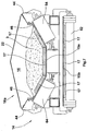
Es zeigen:
- Fig. 1
- Ein erstes Ausführungsbeispiel der Erfindung bei einer Frontlader-Straßenfräse,
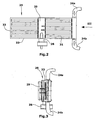
- Fig. 2
- eine Draufsicht auf die auf der vorderen Transporteinrichtung aufliegenden Filtereinrichtung,
- Fig. 3
- eine Ansicht der Filtereinrichtung auf das hintere stirnseitige Ende,
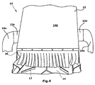
- Fig. 4
- eine Ansicht auf das vordere stirnseitige Ende des hinteren Transportbandes,
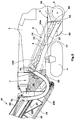
- Fig. 5
- eine vergrößerte Darstellung eines ersten Ausführungsbeispieles der Absaugeinrichtung,
- Fig. 6
- eine vergrößerte Darstellung eines zweiten Ausführungsbeispieles der Absaugeinrichtung, und
- Fig. 7
- einen Querschnitt durch die Transporteinrichtung.
- Fig. 1
- A first embodiment of the invention in a front-loading road milling machine,
- Fig. 2
- a top view of the resting on the front transport means filter device,
- Fig. 3
- a view of the filter device on the rear end face,
- Fig. 4
- a view of the front end face of the rear conveyor belt,
- Fig. 5
- an enlarged view of a first embodiment of the suction device,
- Fig. 6
- an enlarged view of a second embodiment of the suction, and
- Fig. 7
- a cross section through the transport device.
Eine Straßenfräsmaschine 1 zum Bearbeiten von Fahrbahnen in der Ausführungsform
einer Frontladerstraßenfräse ist in Fig. 1 gezeigt. Es versteht sich, dass die
Erfindung auch auf andersartige Fräsmaschinen anwendbar ist, die mit mindestens
einer Transporteinrichtung 14, 18 versehen sind.A
Die Straßenfräsmaschine 1 dient zum Abfräsen von Bodenoberflächen, insbesondere
Fahrbahnen aus Asphalt, Beton o. dgl. Die Straßenfräsmaschine 1 weist ein
Fahrgestell mit beispielsweise vier Kettenlaufwerken 4 auf, das den Maschinenrahmen
2 trägt. Es versteht sich, dass die Kettenlaufwerke durch Räderlaufwerke
ganz oder teilweise substituiert werden können. In dem Maschinenrahmen 2 ist
eine Fräswalze 8 gelagert, die sich quer zur Fahrtrichtung erstreckt. Die Einstellung
der Frästiefe erfolgt vorzugsweise mit Hilfe der Höhenverstellung der Kettenlaufwerke
4. Die in Fig. 1 dargestellte Straßenfräsmaschine 1 wird auch als
Frontlader-Straßenfräse bezeichnet, da sie das abgefräste Material in Fahrtrichtung
nach vorne auf ein Transportfahrzeug 10 befördert. In Fahrtrichtung vor der
Fräswalze 8 ist eine erste, aus einem Transportband bestehende Transporteinrichtung
14 mit einem Fördergurt 15 in einem Schacht 9 des Maschinenrahmens
2 angeordnet, der unter einem Neigungswinkel in dem Maschinenrahmen 2 verläuft.
Die erste Transporteinrichtung 14 befördert das abgefräste Material 3 auf
dem Fördergurt 15 zu einer zweiten, vorzugsweise ebenfalls einen Fördergurt 19
aufweisenden Transporteinrichtung 18. Die zweite Transporteinrichtung 18 ist
über einen verstellbaren Neigungswinkel höhenverstellbar und kann zusätzlich
seitlich um beispielsweise ± 30° verschwenkt werden, so dass auch neben der
Fahrspur der Straßenfräsmaschine stehende Transportfahrzeuge 10 beladen
werden können. Alternativ zu den Fördergurten 15, 19 ist auch der Einsatz von in
einem Kanal angeordneten Förderschnecken möglich.The
Um einen möglichst vollständigen Transport des abgefrästen Materials zu erreichen,
ist die Fräswalze 8 in der Regel von einem Walzenkasten 58 umgeben, bei
dem die in Fahrtrichtung weisende Wand als Schild 52 mit einer Durchtrittsöffnung
56 für das abgefräste Material ausgebildet ist.In order to achieve as complete a transport as possible of the milled material,
the milling
Die Fräswalze 8 ist mit wendelförmig angeordneten Meißelwerkzeugen versehen,
die so angeordnet sind, dass das abgefräste Material 3 zur Durchtrittsöffnung 56
in dem Schild 52 transportiert wird. An dem in Fahrtrichtung hinteren Ende des
Walzenkastens 58 ist eine dicht mit der abgefrästen Bodenoberfläche abschließende
Wand 60 des Walzenkastens 58 vorgesehen, die die gefräste Bodenoberfläche
abzieht, so dass keine Bruchstücke des abgefrästen Materials 3 auf der
abgefrästen Bodenoberfläche verbleiben. Die Wand 60 wird mit ihrer Unterkante
hydraulisch gegen die Bodenoberfläche angepresst, um eine möglichst gute Abdichtung
zu erzielen.The milling
Am Maschinenrahmen 2 ist eine als Bandschuh 50 bezeichnete Bandschutz- und
Stützeinrichtung in einer Führung höhenverstellbar befestigt. Der Bandschuh 50
nimmt das hintere Ende der ersten Transporteinrichtung 14 auf. Die Durchtrittsöffnung
56 des Walzenkastens 58 bildet eine erste Übergabestelle 5, an der das
abgefräste Material von der Fräswalze 8 auf die erste Transporteinrichtung 14
übergeben wird.On
Der Fahrstand befindet sich bei dem Ausführungsbeispiel der Fig. 1 oberhalb der
Fräswalze 8, kann aber wie bei Straßenfräsmaschinen üblich auch im hinteren
oder vorderen Bereich des Maschinenrahmens 2 angeordnet sein.The control station is located in the embodiment of FIG. 1 above the
Milling
Die Fign. 5 und 6 zeigen im Detail die erste Transporteinrichtung 14.The Fign. FIGS. 5 and 6 show in detail the
Die Transporteinrichtung 14 ist in einem vorzugsweise mittig angeordneten
Schacht 9 des Maschinenrahmens 2 befestigt und kann leicht von dem Bandschuh
50 zu Wartungszwecken demontiert werden und durch den Schacht 9 hindurch
ausgebaut werden.The
Die Transporteinrichtung 14 mit dem Fördergurt 15 weist eine Haube 22 auf, die
gemeinsam mit dem oberen Trum 15a des Fördergurtes 15 einen Kanalabschnitt
16a eines Kanals 16 bildet, der sich von dem Walzenkasten 58 bis zum Ende der
zweiten Transporteinrichtung 18 erstreckt. Wie im einzelnen im Querschnitt der
Fig. 7 entnehmbar ist, ist die Haube 22 der ersten Transporteinrichtung 14 mit
Hilfe von Haubenträgern 44 an dem Rahmen der ersten Transporteinrichtung 14
befestigt. Elastische Lippen 46 können an den Haubenträgern 44 beidseitig des
Transportbandes befestigt sein und den oberen Trum 15a des Fördergurtes 15 im
Randbereich über die gesamte Länge des oberen Trums 15a berühren. The
In gleicher Weise kann auch die zweite Transporteinrichtung 18 mit einer Haube
26 versehen sein. Auf diese Weise kann der gesamte Kanal 16 staub- und gasdicht
gegenüber der Umgebung abgedichtet sein, auch wenn die Abdichtung des
vorderen Kanalabschnitts 16b nur dann wirklich erforderlich ist, wenn noch eine
nennenswerte Staubbildung im vorderen Kanalabschnitt 16b überhaupt feststellbar
ist.In the same way, the
Im oberen Bereich der Haube 22 in der Nähe des Abwurfendes aber noch mit
Abstand vor dem Abwurfende, weist die Haube 22 der ersten Transporteinrichtung
14 mindestens einen Stutzen 23, 23a, 23b auf, an den mindestens ein Absaugkanal
24 anschließbar ist. Im Ausführungsbeispiel der Fig. 1 wird der Absaugkanal
24 aus zwei Absaugschläuchen 24a, 24b gebildet, die von den Stutzen
23a, 23b zur Eingangsseite eines Filtergehäuses einer Filtereinrichtung 25 führen,
die vorzugsweise im Bereich des vorderen Kanalabschnitts 16b auf die Haube
26 der vorderen Transporteinrichtung 18 aufgesetzt ist. Die Filtereinrichtung
25 besteht vorzugsweise aus mehreren, z.B. zehn Filterkartuschen 31, die vorzugsweise
parallel geschaltet sind, um eine große Filterfläche zu bilden. Das
Sauggebläse 28 ist ausgangsseitig auf der Reinluftseite angeordnet und wird dadurch
nur mit Reinluft beaufschlagt. Dadurch dass das Sauggebläse 28 hinter der
Filtereinrichtung 25 betrieben wird, werden in vorteilhafter Weise Lagerschäden
und eine Beschädigung der Lüfterschaufeln und weiterer Gebläseelemente vermieden
und eine im Vergleich zum Stand der Technik erheblich höhere Standzeit
der Absaugeinrichtung 20 erreicht. Dadurch, dass sich ein Filterkuchen in der
Filtereinrichtung 25 bilden kann, ist es auch möglich, die bei der Fräsbearbeitung
entstehenden Dämpfe nicht nur aus dem Bereich des Fahrstandes zu entfernen,
sondern auch innerhalb des sich bildenden Filterkuchens in der Filtereinrichtung
25 zu binden. Im Resultat wird demzufolge nicht nur die Staubbeladung, sondern
auch die Belastung der atembaren Luft durch Dämpfe durch die Absaugeinrichtung
20 in erheblichem Umfang reduziert, so dass die Arbeitsplatzbedingungen in
erheblichem Umfang verbessert werden können. Ein Abluftstutzen 29 erlaubt es,
die gereinigte Abluft direkt ins Freie abzublasen. Alternativ kann die Reinluft an
dem vorderen Ende der Filtereinrichtung 25 oder an dem vorderen Ende der vorderen
Transporteinrichtung 18 abgeblasen werden. Das Sauggebläse 28 ermöglicht
eine hohe Luftförderleistung und erzeugt demzufolge einen entsprechend
hohen Unterdruck in dem hinteren Kanalabschnitt 16a und in dem die Fräswalze
8 umgebenden Walzenkasten 58. Die beim Fräsvorgang entstehenden Stäube
und Dämpfe werden daher zuverlässig und mit hoher Effizienz über den
Absaugkanal 24, 24a, 24b abgesaugt.In the upper part of the
Im Bereich der ersten Übergabestelle 5, d.h. an dem unteren Ende der Haube 22
und an der Durchtrittsöffnung 56 des Walzenkastens 58 bzw. des Bandschuhs 50
können flexible Gummimatten die Übergabestelle 5 umfangsmäßig abdichten.
Kleinere Undichtigkeiten des Walzenkastens 58 bzw. zwischen dem Kanal 16 und
dem Walzenkasten 58 sind unerheblich, da durch den Unterdruck keine verunreinigte
Luft austreten kann, sondern allenfalls Luft aus der Umgebung angesaugt
wird. Am oberen Ende der Haube 22 sind, wie am besten aus Fig. 4 ersichtlich,
als Trennmittel zwischen dem ersten und dem zweiten Kanalabschnitt 16a,16b
flexible Klappen 36 vorgesehen, die einerseits das abgefräste Material 3 auf dem
Fördergurt 15 hindurchlassen und andererseits eine Luftströmung entgegen der
Transportrichtung der ersten Transporteinrichtung 14 verhindern. Falls nur ein
einziges Transportband vorgesehen ist, befinden sich die Trennmittel z.B. in der
Mitte der einzigen Transporteinrichtung.In the area of the
Um den hinteren Kanalabschnitt 16a an seinem oberen Ende möglichst gut abzudichten,
sind die Klappen 36 mit Schlitzen versehen. Vorzugsweise sind mehrere
Klappen 36 hintereinander angeordnet, um eine verbesserte Luftabdichtung zwischen
den Kanalabschnitten 16a,16b zu erreichen (Fig. 5).In order to seal the
Es versteht sich, dass die vorzugsweise aus Klappen 36 bestehenden Trennmittel
innerhalb des Kanals 16 auch an anderer Stelle, z.B. in Materialtransportrichtung
hinter der zweiten Übergabestelle 7 im Bereich der zweiten Transporteinrichtung
18 angeordnet sein können. In diesem Fall sind die Absaugkanäle 24a,24b der
Absaugeinrichtung 20 an der Haube 26 der zweiten Transporteinrichtung 18 in
Materialtransporteinrichtung stromaufwärts der Trennmittel, vorzugsweise in der
Nähe der Trennmittel angeschlossen. Der hintere Kanalabschnitt 16a endet somit
an den Trennmitteln, die in Materialtransporteinrichtung stromabwärts der Übergabestelle
7 angeordnet sind.It is understood that the preferably consisting of
Der Fördergurt 15 wird, wie am besten aus Fig. 7 ersichtlich ist, über Stützrollen
62,64 geführt, wobei der obere Trum 15a eine im wesentlichen U-förmige Rinne
bildet, indem die Stützrollen 64 entsprechend geneigt sind. Die untere Stützrolle
62 unterstützt den unteren Trum 15b des Fördergurtes 15. Wie aus den Fign. 3
und 4 ersichtlich ist, befinden sich auf der Oberfläche des Fördergurtes 15 Stege
17, die die Mitnahme des abgefrästen Materials 3 auf dem Fördergurt 15 verbessern.The
An dem oberen Ende der Transporteinrichtung 14 wird das abgefräste Material 3
an der zweiten Übergabestelle 7 in einen Aufnahmetrichter 35 der zweiten
Transporteinrichtung 18 übergeben, wodurch das abgefräste Material 3 über den
Fördergurt 19 bis zum Abwurfende gefördert wird und auf das Transportfahrzeug
10 entsorgt wird. In diesen Aufnahmetrichter 35 kann beispielsweise auch der
Filterkuchen der Filtereinrichtung 25 über eine Klappe 37 im Filtergehäuse 33
entsorgt werden (Fig. 5). Alternativ kann der Filterkuchen in eine aus einem
Staubsammelsack bestehende Sammeleinrichtung 39 eingefüllt werden (Fig. 6),
die an einer Öffnung des Filtergehäuses 33 befestigt ist. Auch bei diesem Ausführungsbeispiel
kann bei Bedarf eine Klappe 37 im Boden des Filtergehäuses 33
vorgesehen sein.At the upper end of the
Die Übergangsstelle an der Übergabestelle 7 ist von aus flexiblen Matten 30 bestehenden
Abdichtmitteln umschlossen, so dass die erste Transporteinrichtung
14 und die zweite Transporteinrichtung 18 einen in Materialtransportrichtung
durchgängigen umfangsmäßig abgedichteten Kanal 16 bilden.The transition point at the
Die in den Fign. 2 und 3 dargestellte aus mehreren Filterkartuschen 31 bestehende
Filtereinrichtung 25 wird in von dem Bedienungspersonal wählbaren Zeitabständen,
z.B. bei Betriebsunterbrechungen, wie z.B. Wechsel des vorrausfahrenden
Lastkraftwagens 10 oder Werkzeugwechsel auf manuellen Befehl hin, z.B.
durch Vibration oder durch Aufgabe eines Druckimpulses in Gegenstromrichtung
gereinigt. Dabei wird der auf den Filterkartuschen 31 aufsitzende Filterkuchen
entfernt. Selbstverständlich kann der Filterkuchen auch in Abhängigkeit des sich
mit zunehmender Betriebsdauer der Filtereinrichtung 25 bildenden Druckverlustes,
oder nach vorgegebenen Zeitabständen automatisch gereinigt werden. Der
von den Filterkartuschen 31 entfernte Filterkuchen kann aufgrund der Neigung
des Unterbodens des Filtergehäuses 33 zu dem hinteren Ende des Filtergehäuses
33 rutschen, wo es beispielsweise über eine Klappe 37 und den Aufnahmetrichter
35 auf die vordere Transporteinrichtung 18 entsorgt werden kann. Dabei ist es
auch möglich, den Filterkuchen zusätzlich durch ein Sprühmittel zu verdichten
und den Zusammenhalt der abgeschiedenen Partikel durch das Sprühmittel zu
erhöhen. In vorteilhafter Weise wird der Filterkuchen hinter den Trennmitteln auf
die vordere Transporteinrichtung 18 aufgegeben.The in Figs. 2 and 3 shown consisting of
Die Absaugschläuche 24a, 24b des Absaugkanals 24 treten, wie in Fig. 2 ersichtlich,
von zwei gegenüberliegenden Seiten in das Filtergehäuse 33 ein, wobei die
Filterpatronen 31 von außen mit der staub- und dampfbeladenen Luft beaufschlagt
werden.The
Claims (11)
dadurch gekennzeichnet, dass die Absaugeinrichtung (20) aus einem Sauggebläse (28), einer Abscheideeinrichtung für Feststoffe und einem Absaugkanal (24) besteht, der an dem hinteren Kanalabschnitt (16a) angeschlossen ist,
dass das Sauggebläse (28) stromabwärts der Abscheideeinrichtung angeordnet ist, und
dass die Abscheideeinrichtung die abgeschiedenen Feststoffe auf die Transporteinrichtung (18) in den in Materialtransportrichtung vorderen Kanalabschnitt (16b) oder in eine Sammeleinrichtung (39) entsorgt und das Sauggebläse (28) die gereinigte Luft in die Umgebung abbläst.Milling machine (1) for processing ground surfaces, comprising a machine frame (2), a milling drum (8) mounted on the machine frame (2), at least one transport device (14, 18) arranged on the machine frame (2), which holds the milled material ( 3) from the milling drum (8), and with a suction device (20) for the air contaminated with dusts and vapors, wherein the milled material (3) on the at least one transport device (14, 18) enclosed by a channel (16) the suction device (20) is connected to a rear channel section (16a) of the channel (16) in the material transport direction and sucks the air contaminated during milling at the milling drum (8) and in the rear channel section (16a) substantially in the material transport direction,
characterized in that the suction device (20) consists of a suction fan (28), a solids separator and a suction channel (24) connected to the rear channel section (16a),
that the suction fan (28) is arranged downstream of the separator, and
in that the separation device discharges the separated solids onto the transport device (18) in the forward channel section (16b) in the material transport direction or into a collecting device (39) and the suction fan (28) blows the cleaned air into the environment.
durch Bilden eines Kanals (16), der das abgefräste Material (3) auf der Transporteinrichtung (14, 18) umgibt, und
durch Absaugen der mit Stäuben und Dämpfen verunreinigten Luft in einem hinteren Kanalabschnitt (16a) des Kanals (16) in Transportrichtung des abgefrästen Materials (3),
gekennzeichnet durch
das Zuführen der in dem hinteren Kanalabschnitt (16a) abgesaugten staubund dampfbeladenen Luft zu einer Abscheideeinrichtung,
das Entsorgen der von der Abscheideeinrichtung abgeschiedenen Feststoffe in eine Sammeleinrichtung (39) oder auf die Transporteinrichtung (14;18) in einem vorderen Kanalabschnitt (16b) des Kanals (16), und
das Abblasen der gereinigten Luft ins Freie durch ein stromabwärts der Abscheideeinrichtung angeordnetes Sauggebläse. Method for disposing of dusts and vapors generated during the milling process on a milling machine for processing ground surfaces, in which the material (3) milled by a milling drum (8) is disposed of via at least one transport device (14, 18),
by forming a channel (16) surrounding the milled material (3) on the conveyor (14, 18), and
by sucking the air contaminated with dusts and vapors in a rear channel section (16a) of the channel (16) in the transport direction of the milled material (3),
marked by
supplying the dust and vapor laden air sucked in the rear channel section (16a) to a separation device,
disposing the solids separated from the separator into a collection device (39) or to the transport device (14; 18) in a front channel section (16b) of the channel (16), and
the blowing off of the cleaned air to the outside through a suction fan arranged downstream of the separating device.
Applications Claiming Priority (2)
| Application Number | Priority Date | Filing Date | Title |
|---|---|---|---|
| DE102004007716A DE102004007716B3 (en) | 2004-02-16 | 2004-02-16 | Road construction asphalt milling machine has dust suction unit located well away from rotating milling tool |
| DE102004007716 | 2004-02-16 |
Publications (3)
| Publication Number | Publication Date |
|---|---|
| EP1564332A2 true EP1564332A2 (en) | 2005-08-17 |
| EP1564332A3 EP1564332A3 (en) | 2006-03-08 |
| EP1564332B1 EP1564332B1 (en) | 2009-10-21 |
Family
ID=34585416
Family Applications (1)
| Application Number | Title | Priority Date | Filing Date |
|---|---|---|---|
| EP05002009A Expired - Lifetime EP1564332B1 (en) | 2004-02-16 | 2005-02-01 | Milling machine and method for working the soil |
Country Status (4)
| Country | Link |
|---|---|
| US (1) | US7219964B2 (en) |
| EP (1) | EP1564332B1 (en) |
| AT (1) | ATE446415T1 (en) |
| DE (2) | DE102004007716B3 (en) |
Cited By (1)
| Publication number | Priority date | Publication date | Assignee | Title |
|---|---|---|---|---|
| CN110258258A (en) * | 2019-07-09 | 2019-09-20 | 三门前庭机械科技有限公司 | A kind of asphalt paving device of smokeless emission |
Families Citing this family (36)
| Publication number | Priority date | Publication date | Assignee | Title |
|---|---|---|---|---|
| US7942605B2 (en) * | 2007-08-24 | 2011-05-17 | Hall David R | Milling drum |
| DE102008008260B4 (en) | 2008-02-08 | 2010-09-09 | Wirtgen Gmbh | Control of a mining machine and mining machine |
| CN101970759B (en) * | 2008-03-12 | 2014-05-07 | 马林公司 | Improved road planer for milling road-surface |
| EP2350390B1 (en) * | 2008-10-21 | 2012-09-05 | Marini S.p.A. | Road planer for milling road-surface |
| DE102009057936A1 (en) | 2009-12-16 | 2011-06-22 | Zuur, Richard Bastiaan, 9695 | Mobile device for the production of floor slits for heating pipes |
| US20110278907A1 (en) * | 2010-05-12 | 2011-11-17 | Diamond Products, Limited | Concrete Profiler With Vacuum System |
| US20120280558A1 (en) | 2011-05-06 | 2012-11-08 | Hall David R | Foam Configured to Suppress Dust on a Surface to be Worked |
| DE102011109450A1 (en) * | 2011-08-04 | 2013-02-07 | Bomag Gmbh | Milling rotor for processing soil material and tillage machine with such a rotor |
| DE102012203649A1 (en) * | 2012-03-08 | 2013-09-12 | Wirtgen Gmbh | Self-propelled road milling machine for working on road surfaces, in particular large milling machine |
| CN102619158B (en) * | 2012-04-17 | 2016-05-04 | 陕西长大实业有限公司 | Pavement milling machine |
| US8985701B2 (en) * | 2012-07-12 | 2015-03-24 | Caterpillar Paving Products Inc. | Cold planer having multi-inlet exhaust system |
| DE102012215013A1 (en) | 2012-08-23 | 2014-02-27 | Wirtgen Gmbh | Self-propelled milling machine, as well as method for unloading milled material |
| DE102012215005A1 (en) * | 2012-08-23 | 2014-02-27 | Wirtgen Gmbh | Self-propelled milling machine, as well as method for steering a self-propelled milling machine |
| DE102012022879B4 (en) * | 2012-08-24 | 2015-10-01 | Bomag Gmbh | Construction machine with a dust extraction device, device for dust extraction for a construction machine and method for extracting dust from a construction machine |
| DE102012019016A1 (en) * | 2012-09-26 | 2014-04-10 | Bomag Gmbh | Material transfer device for a ground milling machine and ground milling machine, in particular road milling machine with such a material transfer device |
| CA2924581C (en) | 2013-10-16 | 2018-01-16 | Roadtec, Inc. | Method and apparatus for controlling dust emissions |
| DE102013226981B4 (en) * | 2013-12-20 | 2016-09-29 | Wirtgen Gmbh | Construction machine, and a method for milling and Abstransportieren a milled material flow of a construction machine |
| CN104099899B (en) * | 2014-07-17 | 2015-12-30 | 中国水利水电第十一工程局有限公司 | A kind of remotely controlled tracked walking concrete extension joint automatic glue injection machine |
| DE102014216603B4 (en) | 2014-08-21 | 2018-02-22 | Wirtgen Gmbh | Self-propelled milling machine, as well as method for unloading milled material |
| DE102014216713B4 (en) | 2014-08-22 | 2018-09-06 | Wirtgen Gmbh | Self-propelled milling machine, as well as method for unloading milled material |
| DE102014216763B4 (en) | 2014-08-22 | 2018-07-26 | Wirtgen Gmbh | Self-propelled milling machine, as well as method for unloading milled material |
| US9873142B2 (en) | 2015-05-04 | 2018-01-23 | Caterpillar Paving Products Inc. | Cold planer exhaust system with access doors |
| DE102016003895A1 (en) | 2016-03-31 | 2017-10-05 | Bomag Gmbh | Ground milling machine, in particular road milling machine, for removing soil material and method for operating a ground milling machine |
| DE102016009516A1 (en) | 2016-08-04 | 2018-02-08 | Bomag Gmbh | road milling machine |
| US20170009410A1 (en) * | 2016-09-22 | 2017-01-12 | Caterpillar Paving Products Inc. | Ventilation system for cold planer |
| DE102016222589B4 (en) | 2016-11-16 | 2020-01-16 | Wirtgen Gmbh | Self-propelled milling machine and method for controlling a self-propelled milling machine |
| DE102017220869A1 (en) | 2017-11-22 | 2019-05-23 | Wirtgen Gmbh | Self-propelled milling machine, method for automatically loading a means of transport with milled material, as well as road or soil treatment unit |
| CN108797291A (en) * | 2018-08-31 | 2018-11-13 | 王凌 | A kind of pavement milling machine dedusting removes milling waste material device |
| DE102019104218A1 (en) | 2019-02-19 | 2020-08-20 | Wirtgen Gmbh | Work train, comprising a tillage machine and another vehicle as well as an automated distance monitoring |
| DE102019132889A1 (en) | 2019-12-03 | 2021-06-10 | Wirtgen Gmbh | Tillage machine with dust extraction with optional filtering of the extracted dust-laden air |
| DE102019132886A1 (en) | 2019-12-03 | 2021-06-10 | Wirtgen Gmbh | Soil cultivation machine with dust extraction and rotatable filter cartridges |
| DE102019132892A1 (en) | 2019-12-03 | 2021-06-10 | Wirtgen Gmbh | Soil tillage machine with filtered dust extraction with an elastically deformable filter housing |
| DE102020005666A1 (en) * | 2020-09-16 | 2022-03-17 | Bomag Gmbh | FLOOR TILLER WITH DUST EXTRACTOR AND SERVICE TUNNEL AND PROCEDURES |
| CN112726357A (en) * | 2020-12-25 | 2021-04-30 | 黄宇 | Asphalt pavement milling device |
| CN113026504B (en) * | 2021-03-19 | 2022-07-01 | 山东省旗舰建设集团有限公司 | Concrete milling equipment for building construction |
| DE102022206278A1 (en) * | 2022-06-22 | 2023-12-28 | Bomag Gmbh | Ground milling machine, in particular road milling machine, recycler or stabilizer, and method for operating a dust extraction device of a ground milling machine |
Citations (1)
| Publication number | Priority date | Publication date | Assignee | Title |
|---|---|---|---|---|
| DE10223819A1 (en) | 2002-05-28 | 2003-12-24 | Wirtgen Gmbh | Milling machine for spreading floor surfaces, as well as method for generating dusts and vapors generated during milling on a milling machine |
Family Cites Families (7)
| Publication number | Priority date | Publication date | Assignee | Title |
|---|---|---|---|---|
| USRE24004E (en) * | 1955-05-17 | Collapsible mining head | ||
| US2100178A (en) * | 1936-05-11 | 1937-11-23 | Pittsburgh Coal Company | Coal mining machine |
| DE2528418A1 (en) * | 1975-06-26 | 1977-01-20 | Errut Prod Ltd | Groove cutting device for road surfaces - has drum cutting system with intermediate drum segments and drive shafts |
| US4561145A (en) * | 1984-02-16 | 1985-12-31 | Latham Winchester E | Continuous sweep for road planing and milling machines |
| US5063713A (en) * | 1990-12-20 | 1991-11-12 | Accent Stripe Inc. | Surface abrading and particle collection device |
| ITVI980132A1 (en) * | 1998-07-09 | 2000-01-09 | Bitelli Spa | DEVICE FOR SUCTION AND TREATMENT OF DUST PRODUCED BY SCARIFIER MACHINES |
| US6733086B1 (en) * | 2002-03-15 | 2004-05-11 | Ri Properties, Inc. | Vacuum system for milling machine |
-
2004
- 2004-02-16 DE DE102004007716A patent/DE102004007716B3/en not_active Expired - Fee Related
-
2005
- 2005-02-01 AT AT05002009T patent/ATE446415T1/en not_active IP Right Cessation
- 2005-02-01 EP EP05002009A patent/EP1564332B1/en not_active Expired - Lifetime
- 2005-02-01 DE DE502005008355T patent/DE502005008355D1/en not_active Expired - Lifetime
- 2005-02-15 US US11/057,838 patent/US7219964B2/en not_active Expired - Lifetime
Patent Citations (1)
| Publication number | Priority date | Publication date | Assignee | Title |
|---|---|---|---|---|
| DE10223819A1 (en) | 2002-05-28 | 2003-12-24 | Wirtgen Gmbh | Milling machine for spreading floor surfaces, as well as method for generating dusts and vapors generated during milling on a milling machine |
Cited By (2)
| Publication number | Priority date | Publication date | Assignee | Title |
|---|---|---|---|---|
| CN110258258A (en) * | 2019-07-09 | 2019-09-20 | 三门前庭机械科技有限公司 | A kind of asphalt paving device of smokeless emission |
| CN110258258B (en) * | 2019-07-09 | 2021-06-08 | 山东广通汽车科技股份有限公司 | Smokeless asphalt laying device that discharges |
Also Published As
| Publication number | Publication date |
|---|---|
| ATE446415T1 (en) | 2009-11-15 |
| US20050179309A1 (en) | 2005-08-18 |
| EP1564332A3 (en) | 2006-03-08 |
| DE502005008355D1 (en) | 2009-12-03 |
| EP1564332B1 (en) | 2009-10-21 |
| US7219964B2 (en) | 2007-05-22 |
| DE102004007716B3 (en) | 2005-06-16 |
Similar Documents
| Publication | Publication Date | Title |
|---|---|---|
| DE102004007716B3 (en) | Road construction asphalt milling machine has dust suction unit located well away from rotating milling tool | |
| EP1507925B1 (en) | Suction device and suction method for the disposal of dust in milling machines | |
| EP3225738A1 (en) | Ground milling machine, in particular road milling machine, for removing soil material and method for operating a ground milling machine | |
| DE3710283C2 (en) | Equipment for the removal and removal of contaminated soil | |
| DE69928176T2 (en) | Milling machine with a device for suction and processing of dust | |
| DE102005035480A1 (en) | Milling machine for road coverings comprises a dust box arranged in front of a ventilator and assigned to a suction channel having an outlet for passing clean waste air directly into the atmosphere | |
| DD245686A5 (en) | RUNNING MACHINE FOR EXTRACTION OF THE SCOTTER FROM A SCOOTER BED | |
| EP0824164B1 (en) | Track maintenance machine for removing the ballast | |
| EP2835471A2 (en) | Self-propelled street milling machine and method for milling and transporting a flow of milled material | |
| DE4341240C2 (en) | Suction machine for suctioning ballast from a ballast bed | |
| DE202004002444U1 (en) | Ground cutting machine, e.g. for road surface renewal, has a suction arrangement with a suction blower positioned downstream of a solid material separation arrangement | |
| DE202005007992U1 (en) | Sand blaster, especially for sand blasting workpieces of rock, glass or wood, has sand blasting tube that can be displaced perpendicularly with respect to plane spanned by vertical and horizontal directions | |
| EP3597828B1 (en) | Road milling machine | |
| DE29703454U1 (en) | Movable track construction machine | |
| DE3912885A1 (en) | Road surface milling machine - has suction device which removes broken out material straight from milling roller | |
| DE3605448C2 (en) | ||
| EP3832021B1 (en) | Soil treatment machine with dust extraction with optional filtering of the suction dust-polled air | |
| EP3832020B1 (en) | Soil treatment machine with filtered dust extraction with elastically deformable filter housing | |
| EP0663472A1 (en) | Machine for cleaning the ballast of a railway track | |
| CH364803A (en) | Self-picking sweeper for runways, streets, paths or the like with vacuum delivery | |
| EP2135540B1 (en) | Floor cleaning machine | |
| DE19524203A1 (en) | Sweeper with dust extraction | |
| EP3832022B1 (en) | Soil treatment machine with dust extraction and rotating filter cartridges | |
| DE8709504U1 (en) | Road milling machine for milling road surfaces | |
| DE4343487A1 (en) | Suction-cleaning machine for the railway superstructure |
Legal Events
| Date | Code | Title | Description |
|---|---|---|---|
| PUAI | Public reference made under article 153(3) epc to a published international application that has entered the european phase |
Free format text: ORIGINAL CODE: 0009012 |
|
| AK | Designated contracting states |
Kind code of ref document: A2 Designated state(s): AT BE BG CH CY CZ DE DK EE ES FI FR GB GR HU IE IS IT LI LT LU MC NL PL PT RO SE SI SK TR |
|
| AX | Request for extension of the european patent |
Extension state: AL BA HR LV MK YU |
|
| PUAL | Search report despatched |
Free format text: ORIGINAL CODE: 0009013 |
|
| AK | Designated contracting states |
Kind code of ref document: A3 Designated state(s): AT BE BG CH CY CZ DE DK EE ES FI FR GB GR HU IE IS IT LI LT LU MC NL PL PT RO SE SI SK TR |
|
| AX | Request for extension of the european patent |
Extension state: AL BA HR LV MK YU |
|
| 17P | Request for examination filed |
Effective date: 20060412 |
|
| AKX | Designation fees paid |
Designated state(s): AT BE BG CH CY CZ DE DK EE ES FI FR GB GR HU IE IS IT LI LT LU MC NL PL PT RO SE SI SK TR |
|
| 17Q | First examination report despatched |
Effective date: 20080214 |
|
| GRAP | Despatch of communication of intention to grant a patent |
Free format text: ORIGINAL CODE: EPIDOSNIGR1 |
|
| GRAS | Grant fee paid |
Free format text: ORIGINAL CODE: EPIDOSNIGR3 |
|
| GRAA | (expected) grant |
Free format text: ORIGINAL CODE: 0009210 |
|
| AK | Designated contracting states |
Kind code of ref document: B1 Designated state(s): AT BE BG CH CY CZ DE DK EE ES FI FR GB GR HU IE IS IT LI LT LU MC NL PL PT RO SE SI SK TR |
|
| REG | Reference to a national code |
Ref country code: GB Ref legal event code: FG4D Free format text: NOT ENGLISH |
|
| REG | Reference to a national code |
Ref country code: CH Ref legal event code: EP |
|
| REG | Reference to a national code |
Ref country code: IE Ref legal event code: FG4D |
|
| REF | Corresponds to: |
Ref document number: 502005008355 Country of ref document: DE Date of ref document: 20091203 Kind code of ref document: P |
|
| REG | Reference to a national code |
Ref country code: SE Ref legal event code: TRGR |
|
| LTIE | Lt: invalidation of european patent or patent extension |
Effective date: 20091021 |
|
| PG25 | Lapsed in a contracting state [announced via postgrant information from national office to epo] |
Ref country code: IS Free format text: LAPSE BECAUSE OF FAILURE TO SUBMIT A TRANSLATION OF THE DESCRIPTION OR TO PAY THE FEE WITHIN THE PRESCRIBED TIME-LIMIT Effective date: 20100221 Ref country code: ES Free format text: LAPSE BECAUSE OF FAILURE TO SUBMIT A TRANSLATION OF THE DESCRIPTION OR TO PAY THE FEE WITHIN THE PRESCRIBED TIME-LIMIT Effective date: 20100201 Ref country code: FI Free format text: LAPSE BECAUSE OF FAILURE TO SUBMIT A TRANSLATION OF THE DESCRIPTION OR TO PAY THE FEE WITHIN THE PRESCRIBED TIME-LIMIT Effective date: 20091021 Ref country code: LT Free format text: LAPSE BECAUSE OF FAILURE TO SUBMIT A TRANSLATION OF THE DESCRIPTION OR TO PAY THE FEE WITHIN THE PRESCRIBED TIME-LIMIT Effective date: 20091021 Ref country code: PT Free format text: LAPSE BECAUSE OF FAILURE TO SUBMIT A TRANSLATION OF THE DESCRIPTION OR TO PAY THE FEE WITHIN THE PRESCRIBED TIME-LIMIT Effective date: 20100222 |
|
| REG | Reference to a national code |
Ref country code: IE Ref legal event code: FD4D |
|
| PG25 | Lapsed in a contracting state [announced via postgrant information from national office to epo] |
Ref country code: SI Free format text: LAPSE BECAUSE OF FAILURE TO SUBMIT A TRANSLATION OF THE DESCRIPTION OR TO PAY THE FEE WITHIN THE PRESCRIBED TIME-LIMIT Effective date: 20091021 Ref country code: PL Free format text: LAPSE BECAUSE OF FAILURE TO SUBMIT A TRANSLATION OF THE DESCRIPTION OR TO PAY THE FEE WITHIN THE PRESCRIBED TIME-LIMIT Effective date: 20091021 |
|
| PG25 | Lapsed in a contracting state [announced via postgrant information from national office to epo] |
Ref country code: DK Free format text: LAPSE BECAUSE OF FAILURE TO SUBMIT A TRANSLATION OF THE DESCRIPTION OR TO PAY THE FEE WITHIN THE PRESCRIBED TIME-LIMIT Effective date: 20091021 Ref country code: EE Free format text: LAPSE BECAUSE OF FAILURE TO SUBMIT A TRANSLATION OF THE DESCRIPTION OR TO PAY THE FEE WITHIN THE PRESCRIBED TIME-LIMIT Effective date: 20091021 Ref country code: RO Free format text: LAPSE BECAUSE OF FAILURE TO SUBMIT A TRANSLATION OF THE DESCRIPTION OR TO PAY THE FEE WITHIN THE PRESCRIBED TIME-LIMIT Effective date: 20091021 Ref country code: BG Free format text: LAPSE BECAUSE OF FAILURE TO SUBMIT A TRANSLATION OF THE DESCRIPTION OR TO PAY THE FEE WITHIN THE PRESCRIBED TIME-LIMIT Effective date: 20100121 Ref country code: IE Free format text: LAPSE BECAUSE OF FAILURE TO SUBMIT A TRANSLATION OF THE DESCRIPTION OR TO PAY THE FEE WITHIN THE PRESCRIBED TIME-LIMIT Effective date: 20091021 |
|
| PLBE | No opposition filed within time limit |
Free format text: ORIGINAL CODE: 0009261 |
|
| STAA | Information on the status of an ep patent application or granted ep patent |
Free format text: STATUS: NO OPPOSITION FILED WITHIN TIME LIMIT |
|
| BERE | Be: lapsed |
Owner name: WIRTGEN G.M.B.H. Effective date: 20100228 |
|
| PG25 | Lapsed in a contracting state [announced via postgrant information from national office to epo] |
Ref country code: SK Free format text: LAPSE BECAUSE OF FAILURE TO SUBMIT A TRANSLATION OF THE DESCRIPTION OR TO PAY THE FEE WITHIN THE PRESCRIBED TIME-LIMIT Effective date: 20091021 Ref country code: CZ Free format text: LAPSE BECAUSE OF FAILURE TO SUBMIT A TRANSLATION OF THE DESCRIPTION OR TO PAY THE FEE WITHIN THE PRESCRIBED TIME-LIMIT Effective date: 20091021 |
|
| 26N | No opposition filed |
Effective date: 20100722 |
|
| REG | Reference to a national code |
Ref country code: CH Ref legal event code: PL |
|
| PG25 | Lapsed in a contracting state [announced via postgrant information from national office to epo] |
Ref country code: CH Free format text: LAPSE BECAUSE OF NON-PAYMENT OF DUE FEES Effective date: 20100228 Ref country code: GR Free format text: LAPSE BECAUSE OF FAILURE TO SUBMIT A TRANSLATION OF THE DESCRIPTION OR TO PAY THE FEE WITHIN THE PRESCRIBED TIME-LIMIT Effective date: 20100122 Ref country code: LI Free format text: LAPSE BECAUSE OF NON-PAYMENT OF DUE FEES Effective date: 20100228 Ref country code: MC Free format text: LAPSE BECAUSE OF NON-PAYMENT OF DUE FEES Effective date: 20100301 |
|
| PG25 | Lapsed in a contracting state [announced via postgrant information from national office to epo] |
Ref country code: BE Free format text: LAPSE BECAUSE OF NON-PAYMENT OF DUE FEES Effective date: 20100228 |
|
| PG25 | Lapsed in a contracting state [announced via postgrant information from national office to epo] |
Ref country code: AT Free format text: LAPSE BECAUSE OF NON-PAYMENT OF DUE FEES Effective date: 20100201 |
|
| PG25 | Lapsed in a contracting state [announced via postgrant information from national office to epo] |
Ref country code: CY Free format text: LAPSE BECAUSE OF FAILURE TO SUBMIT A TRANSLATION OF THE DESCRIPTION OR TO PAY THE FEE WITHIN THE PRESCRIBED TIME-LIMIT Effective date: 20091021 |
|
| PG25 | Lapsed in a contracting state [announced via postgrant information from national office to epo] |
Ref country code: HU Free format text: LAPSE BECAUSE OF FAILURE TO SUBMIT A TRANSLATION OF THE DESCRIPTION OR TO PAY THE FEE WITHIN THE PRESCRIBED TIME-LIMIT Effective date: 20100422 Ref country code: LU Free format text: LAPSE BECAUSE OF NON-PAYMENT OF DUE FEES Effective date: 20100201 |
|
| PG25 | Lapsed in a contracting state [announced via postgrant information from national office to epo] |
Ref country code: TR Free format text: LAPSE BECAUSE OF FAILURE TO SUBMIT A TRANSLATION OF THE DESCRIPTION OR TO PAY THE FEE WITHIN THE PRESCRIBED TIME-LIMIT Effective date: 20091021 |
|
| REG | Reference to a national code |
Ref country code: FR Ref legal event code: PLFP Year of fee payment: 11 |
|
| REG | Reference to a national code |
Ref country code: FR Ref legal event code: PLFP Year of fee payment: 12 |
|
| REG | Reference to a national code |
Ref country code: FR Ref legal event code: PLFP Year of fee payment: 13 |
|
| REG | Reference to a national code |
Ref country code: FR Ref legal event code: PLFP Year of fee payment: 14 |
|
| PGFP | Annual fee paid to national office [announced via postgrant information from national office to epo] |
Ref country code: GB Payment date: 20220221 Year of fee payment: 18 Ref country code: DE Payment date: 20220217 Year of fee payment: 18 |
|
| PGFP | Annual fee paid to national office [announced via postgrant information from national office to epo] |
Ref country code: SE Payment date: 20220221 Year of fee payment: 18 Ref country code: NL Payment date: 20220216 Year of fee payment: 18 Ref country code: IT Payment date: 20220228 Year of fee payment: 18 Ref country code: FR Payment date: 20220221 Year of fee payment: 18 |
|
| REG | Reference to a national code |
Ref country code: DE Ref legal event code: R119 Ref document number: 502005008355 Country of ref document: DE |
|
| REG | Reference to a national code |
Ref country code: SE Ref legal event code: EUG |
|
| REG | Reference to a national code |
Ref country code: NL Ref legal event code: MM Effective date: 20230301 |
|
| GBPC | Gb: european patent ceased through non-payment of renewal fee |
Effective date: 20230201 |
|
| PG25 | Lapsed in a contracting state [announced via postgrant information from national office to epo] |
Ref country code: SE Free format text: LAPSE BECAUSE OF NON-PAYMENT OF DUE FEES Effective date: 20230202 |
|
| PG25 | Lapsed in a contracting state [announced via postgrant information from national office to epo] |
Ref country code: NL Free format text: LAPSE BECAUSE OF NON-PAYMENT OF DUE FEES Effective date: 20230301 |
|
| PG25 | Lapsed in a contracting state [announced via postgrant information from national office to epo] |
Ref country code: GB Free format text: LAPSE BECAUSE OF NON-PAYMENT OF DUE FEES Effective date: 20230201 |
|
| PG25 | Lapsed in a contracting state [announced via postgrant information from national office to epo] |
Ref country code: IT Free format text: LAPSE BECAUSE OF NON-PAYMENT OF DUE FEES Effective date: 20230201 Ref country code: GB Free format text: LAPSE BECAUSE OF NON-PAYMENT OF DUE FEES Effective date: 20230201 Ref country code: FR Free format text: LAPSE BECAUSE OF NON-PAYMENT OF DUE FEES Effective date: 20230228 Ref country code: DE Free format text: LAPSE BECAUSE OF NON-PAYMENT OF DUE FEES Effective date: 20230901 |