EP1564377B1 - Gasturbinen-schaufel und -rotorscheibe mit einem reduzierten Reibungskoeffizient an der Schaufel- und Rotorscheibe-grenzfläche - Google Patents
Gasturbinen-schaufel und -rotorscheibe mit einem reduzierten Reibungskoeffizient an der Schaufel- und Rotorscheibe-grenzfläche Download PDFInfo
- Publication number
- EP1564377B1 EP1564377B1 EP05250384A EP05250384A EP1564377B1 EP 1564377 B1 EP1564377 B1 EP 1564377B1 EP 05250384 A EP05250384 A EP 05250384A EP 05250384 A EP05250384 A EP 05250384A EP 1564377 B1 EP1564377 B1 EP 1564377B1
- Authority
- EP
- European Patent Office
- Prior art keywords
- bearing surface
- area
- stress ratio
- blade
- component
- Prior art date
- Legal status (The legal status is an assumption and is not a legal conclusion. Google has not performed a legal analysis and makes no representation as to the accuracy of the status listed.)
- Expired - Lifetime
Links
Images
Classifications
-
- F—MECHANICAL ENGINEERING; LIGHTING; HEATING; WEAPONS; BLASTING
- F01—MACHINES OR ENGINES IN GENERAL; ENGINE PLANTS IN GENERAL; STEAM ENGINES
- F01D—NON-POSITIVE DISPLACEMENT MACHINES OR ENGINES, e.g. STEAM TURBINES
- F01D5/00—Blades; Blade-carrying members; Heating, heat-insulating, cooling or antivibration means on the blades or the members
- F01D5/30—Fixing blades to rotors; Blade roots ; Blade spacers
- F01D5/3092—Protective layers between blade root and rotor disc surfaces, e.g. anti-friction layers
-
- F—MECHANICAL ENGINEERING; LIGHTING; HEATING; WEAPONS; BLASTING
- F04—POSITIVE - DISPLACEMENT MACHINES FOR LIQUIDS; PUMPS FOR LIQUIDS OR ELASTIC FLUIDS
- F04D—NON-POSITIVE-DISPLACEMENT PUMPS
- F04D29/00—Details, component parts, or accessories
- F04D29/26—Rotors specially for elastic fluids
- F04D29/32—Rotors specially for elastic fluids for axial flow pumps
- F04D29/34—Blade mountings
Definitions
- This invention relates to gas turbine engine rotor blades, discs and bladed discs, and in particular concerns the attachment of rotor blades in blade fixing slots in rotor discs.
- Dovetail attachments are commonly used to secure fan and/or compressor blades to discs in gas turbine engines.
- Dovetail shaped blade roots are located in similarly shaped slots circumferentially spaced around the rim of the rotor disc.
- the dovetail attachment reacts the centrifugal force generated by the blade during engine operation by contact with the disc on flat bearing surfaces, commonly referred to as "flanks".
- Dovetail root cracking is a common occurrence in gas turbine engines due to high stress concentrations at the upper edge of contact (EOC) which are not adequately predicted by known finite element methods due to the extremely high stress gradients present at the edge of contact.
- Other factors that contribute to dovetail cracking include high coefficients of friction at the contact surfaces, high frequency blade excitation (high cycle fatigue) and fretting due to movement of the contact surfaces of the dovetail attachment.
- Dry-film-lubricant (DFL) is commonly applied to the contact surfaces of the dovetail attachment, principally to reduce fretting but also to reduce the coefficient of friction at the contact surfaces.
- Dry-film-lubricants have a tendency to degrade relatively quickly in gas turbine engine applications due to heavy loading and wear, with the rate of wear varying along the length of the dovetail contact surfaces.
- European Patent Application No. 0496503A1 (General Electric) describes the application of a dry film lubricant to the full length of the slots and roots of a titanium alloy turbine rotor assembly.
- European Patent Application No. 0496503A1 (General Electric) describes the application of a dry film lubricant to the full length of the slots and roots of a titanium alloy turbine rotor assembly.
- a load bearing component for a gas turbine engine comprising at least one load bearing surface, characterised in that a dry film lubricant coating is provided on selected area(s) of the bearing surface with the remaining area(s) of said bearing surface being substantially free of the said coating, the selected area(s) of coating being distributed in a predetermined pattern produced by determining the distribution of steady and cyclic stresses acting on the said bearing surface of the uncoated component under engine operating conditions, determining the stress ratio distribution for the said uncoated surface under the said operating conditions, and applying a dry film lubricant coating to area(s) of the bearing surface having a stress ratio above a pre-determined stress ratio threshold value.
- a rotor disc for a gas turbine engine having a plurality of blade root fixing slots circumferentially spaced around the rim of the disc for fixing respective blades to the disc; each slot having at least one bearing surface on each side of the slot for contact with corresponding surfaces on opposite flanks of a blade, wherein at least one selected area of the bearing surface of each slot which, in operation, is an area of alternating stress greater than about 50 MPa (peak to peak), is configured to have a co-efficient of friction lower than the remainder of the slot surface.
- the present invention is based on observations that a relationship exists between the coefficient of friction of the bearing surfaces and blade root steady stresses with high blade root friction resulting in high steady stresses.
- the present inventor has demonstrated that where the coefficient of friction varies along the contact surfaces of the dovetail root, due to degradation of a dry-film-lubricant applied to the surfaces, the areas having a relatively high coefficient of friction are more highly loaded than areas where the lubricant is not degraded and where a relatively low coefficient of a friction exists. Where the coefficient of friction varies along the length of the dovetail contact surfaces the areas of high coefficient of friction take proportionately more load in terms of steady stress than areas of low coefficient of friction, effectively off loading the areas having a low coefficient of friction.
- Cyclic stresses are substantially due to the vibration mode shape of the blade and therefore only specific sections of the blade root are exposed to high alternating stress, for example the leading and trailing edges.
- dovetail root cracking is more prevalent where high steady stresses occur due to breakdown of a friction reducing coating in combination with relatively high alternating stresses due to blade vibration.
- the combination of high steady and alternating stresses leads to high stress ratios and therefore reduced fatigue life.
- a "high" alternating stress can be taken to be any stress greater than about 50 MPa (peak to peak).
- the "stress ratio” is defined as the ratio of actual alternating stress of the allowable alternating stress for failure in 10 7 cycles at a given steady stress. A stress ratio of greater than about 40% in the examples presented will result in failure of the components. Hence a stress ratio of greater than 40% is taken to be a "high" stress ratio.
- dry-film-lubricant has been applied to compressor/fan blade and disc dovetail roots along the whole flank (contact surfaces), principally to reduce root fretting but also to reduce coefficient of friction and therefore steady stresses.
- the present invention uses the principle of varying the co-efficient of friction of contact surfaces to optimise stresses within the blade root and in particular the stress ratio distribution along the length of the contact surfaces (flanks) of the blade root.
- the present invention enables the distribution of steady stresses to be manipulated by, for example, using selective application of dry-film-lubricant to areas of high alternating stress thereby offloading at least part of the load generating the high steady stresses to areas of low alternating stress. In this way it is possible to optimise the stress ratio distribution over the whole of the blade root contact surfaces to ensure that no area of the contact surface is subject to both high alternating and steady stresses. This readily enables the maximum stress ratio to be reduced for particular engine operating conditions.
- the bearing surfaces of the rotor blade root each comprise a leading edge end and a trailing edge end.
- the region configured to have a low co-efficient of friction is a region where the stress distribution along the flanks requires it and is configured in such a manner as to achieve the desired result.
- a dry film lubricant coating is applied to the root in the region of the leading edge end and/or the trailing edge end. In this way, in embodiments where the alternating stresses are highest at the leading and trailing edge ends of the root bearing surfaces, for example due to blade vibration, the steady state contact stresses can be reduced in these areas by the selective application of a dry-film-lubricant to these areas with the region between the trailing and leading edge ends being substantially free of lubricant.
- the selected area(s) having a relatively low co-efficient of friction may be between 40-70% of the surface area of the bearing surfaces.
- the selected area(s) having a relatively low co-efficient of friction may be between 20-60% of the surface area of the bearing surfaces.
- the selected area(s) may cover substantially the same size areas of the bearing surfaces at the leading and trailing edge ends. This is particularly desirable where the alternating stresses acting on the contact bearing surfaces are of similar magnitude at the leading and trailing edge end of the blade root.
- the root comprises a dovetail root having a substantially flat bearing surface on each flank of the root.
- the invention also contemplates other types of blade fixing roots, for example fir tree roots, having a plurality of load bearing lands.
- the rotor blade comprises a fan or compressor blade having a dovetail root.
- the selective area(s) to which is configured to have a relatively low co-efficient of friction is/are subject to dynamic contact stresses, during engine operation, greater than the average of the dynamic contact stresses on the bearing surface due to blade vibration.
- the areas of relatively low co-efficient of friction on the respective bearing surfaces of the blade root and the disc slot are arranged such that they are in contact with each other in the disc assembly. In this way the stress ratio generated at the mating contact surfaces can be minimised.
- a method of applying a dry film lubricant coating to a load bearing surface of gas turbine engine component comprising the steps of determining the distribution of steady and cyclic stresses acting on the said bearing surface of the uncoated component under engine operating conditions, determining the stress ratio distribution for the said uncoated surface under the said operating conditions, applying a dry film lubricant to area(s) of the bearing surface having a stress ratio above a pre-determined stress ratio threshold value.
- a load bearing assembly comprising at least one pair of load bearing surfaces in contact with each other for supporting steady state and dynamic loads in use, and at least one selected area on at least one of the bearing surfaces which, in operation, is an area of alternating stress greater than about 50 MPa (peak to peak), is configured to have a co-efficient friction lower than the remainder of the bearing surfaces.
- the selected areas have a co-efficient the at least one selected area is provided by the application of a dry film lubricant to said at least one selected area, with the remaining area(s) of said bearing surfaces being substantially free of the said coating.
- Configuring selected areas of bearing surfaces of highly loaded components to have a lower co-efficient of friction than adjacent areas finds particular application to gas turbine engine components as shown in Figures 1 and 2 .
- One means by which this can be achieved is the selective application of dry film lubricant to selected areas.
- the selective application of dry-film-lubricant to the components shown in Figures 1 and 2 is discussed in relation to the fan section of a gas turbine engine.
- the present invention is equally applicable to the compressor stages of the engine as well as the fan.
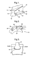
- Figure 1 shows the root section 10 of a gas turbine engine fan blade.
- the root section is disposed on the underside of the blade platform 12 with the aerofoil section 14 of the blade on the opposite side thereof.
- the root section is in the form of a dovetail root and comprises a root shank 16 and a dovetail shaped end section 18.
- the root shank 16 has a substantially constant cross section area in the spanwise direction of the blade as defined by a pair of generally parallel side flank surfaces 20 on opposite sides of the blade.
- the dovetail section 18 comprises a pair of inclined bearing surfaces 22, which diverge by equal amounts in the spanwise direction of the blade away from the blade platform 12.
- the underside of the root 18 between the bearing surfaces 22 is slightly rounded to give the dovetail end shape.
- FIG. 2 shows part of the radially outer periphery of a fan disc 24 having a plurality of dovetail slots 26 circumferentially spaced around the periphery and opening radially for receiving respective dovetail root fan blades 10.
- Each dovetail slot 26 comprises a pair of inclined bearing surfaces 28, on opposite sides of the slot that diverge from the outer periphery towards the hub of the disc.
- the angle of divergence of the bearing surfaces 28 is the same as the angle of divergence of the bearing surfaces 22 with the dimensions of the slot being such that the blade root sections 10 slide into the slots to be attached to the disc as shown in the drawing of Figure 3 .
- the dovetail roots 22 rest in the slots 26.
- the rotational forces generated by the rotor blades cause the root bearing surfaces 22 to contact the slot bearing surfaces 28 so that the centrifugal force generated by the rotating fan blades is transferred to the disc 24 by the mating surfaces 22, 28.
- the magnitude of the force is a function of the rotational speed of the bladed rotor assembly and therefore the higher the operational speed of the rotor the greater the loading on the bearing surfaces 22, 28.
- the steady stresses acting on the surfaces 22, 28 constitute steady stresses since they are principally dependent on the speed of rotation of the engine shaft to which the fan is attached to and at constant shaft speeds, combined with the friction at the interface between the two components.
- the contact surfaces 22, 28 are also subject to high frequency cyclic contact stresses due to vibration of the fan blades in the slots 26.
- the deleterious effects of the combined steady (or mean) and alternating stresses acting on the bearing surfaces 22 of the dovetail roots are mitigated by configuring selected areas of the bearing contact surfaces 22 to have a lower co-efficient of friction than the remainder of the surface.
- This is achieved by the selective application of a dry-film-lubricant to selective areas of the bearing contact surfaces 22.
- a dry-film-lubricant is applied to the leading edge end 30 and the trailing edge end 32 of the bearing surfaces 22.
- the dry-film-lubricant is applied over the whole width of the bearing surfaces at the leading and trailing edge ends with the central region 34 of the surface 22 between the ends 30 and 32 being substantially free of the dry-film-lubricant coating.
- the area of the central section 34 of the bearing surfaces 22 constitutes about 50% of the total surface area of the bearing surface 22 with the coated areas 30 and 32 being of substantially equal area and each comprising about 25% of the total surface area.
- Selective areas of the bearing surfaces 28 of the dovetail slots are also provided with a dry-film-lubricant surface coating. Dry-film-lubricant is applied to the surfaces 28 at the opposite ends of the slot such that the coated region 30 on the blade root bearing surface 22 contacts a coated region 36 at the leading edge side of the disc slot, and the coated region 32 at the trailing edge end of the blade root contacts a region 38 at the trailing edge end of the slot.
- the dimensions of the coated regions 30 and 36 and 32 and 38 are such that the coated regions of the root and the slot are substantially the same and in contact with each other in the bladed disc assembly.
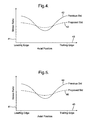
- Figure 4 shows the variation of the stress ratio of the steady and alternating stresses acting on the bearing surface 22 of the blade root from the leading edge end to the trailing edge end at a particular engine operating condition.
- the "Y" axis 41 represents the stress ratio value and the "X" axis 43 represents the distance along the root from the trailing edge to the leading edge and thereof.
- the solid line 40 in the drawing of Figure 3 represents the stress ratio variation from the leading edge end (left hand side) to the trailing edge end (right hand side) of the bearing surface 22 where the whole of the surface is coated with a dry-film-lubricant.
- the broken line 42 represents the stress ratio variation where the bearing surface 22 is coated with dry-film-lubricant on selective areas 30 and 32 as shown in the drawing of Figure 1 .
- Figure 5 shows the variation of stress ratio between the leading edge (left hand side) and trailing edge (right hand side) end of the bearing surface 28 of a dovetail slot.
- Line 44 represents the stress ratio variation along the length of the slot for a fully coated bearing surface 28 while line 46 represents the stress ratio variation for the part coated bearing surface 28 shown in and described with reference to Figure 2 .
- the stress ratio variation shown in Figure 5 is very similar to that shown in Figure 4 with the fully coated bearing surface 28 having a higher stress ratio at the leading edge and trailing edge ends and a lower stress ratio at the central part of the bearing surface when compared with the stress ratio variation 46 for the part coated bearing surface 28.
Landscapes
- Engineering & Computer Science (AREA)
- Mechanical Engineering (AREA)
- General Engineering & Computer Science (AREA)
- Structures Of Non-Positive Displacement Pumps (AREA)
- Sliding-Contact Bearings (AREA)
Claims (8)
- Lasttragende Komponente für ein Gasturbinentriebwerk, mit mindestens einer lasttragenden Fläche (22, 28), dadurch gekennzeichnet, dass auf (einem) gewählten Bereich(en) (30, 32, 36) der tragenden Fläche ein Trockenfilm-Schmiermittelüberzug vorgesehen ist, während der (die) verbleibende(n) Bereich(e) (34) dieser tragenden Fläche (22, 28) im wesentlichen frei von diesem Überzug ist (sind), wobei der (die) gewählte(n) Bereich(e) des Überzugs in einem vorbestimmten Muster verteilt ist (sind), das durch Bestimmung der Verteilung stationärer und zyklischer Spannungen, die auf die genannte tragende Fläche (22, 28) der nicht überzogenen Komponente unter Triebwerksbetriebsbedingungen wirken, Bestimmen der Spannungsverhältnisverteilung für die nicht überzogene Fläche unter den genannten Betriebsbedingungen, und Aufbringen eines Trockenfilm-Schmiermittelüberzugs auf (einen) Bereich(e) (30, 32, 36) der tragenden Fläche (22, 28) mit einem Spannungsverhältnis oberhalb eines vorgegebenen Spannungsverhältnis-Schwellenwerts erzeugt wird.
- Lasttragende Komponente nach Anspruch 1, wobei das vorbestimmte Muster weiter durch Bestimmen, welche(r) Bereich(e) auf der genannten tragenden Fläche (22, 28) der nicht überzogenen Komponente im Betrieb dynamischen Berührungsspannungen ausgesetzt ist/sind, die größer als die mittlere dynamische Berührungsspannung auf der tragenden Fläche (22, 28) sind, und durch Aufbringen eines Trockenfilm-Schmiermittelüberzugs auf (einen) Bereich(e) (30, 32, 36) der tragenden Fläche (22, 28) erzeugt wird, die eine oberhalb eines vorgegebenen dynamischen Berührungsspannungs-Schwellenwerts liegende dynamische Berührungsspannung erfahren.
- Lasttragende Baugruppe für ein Gasturbinentriebwerk mit mindestens einem Paar lasttragender Flächen (22, 28), die miteinander in Berührung stehen, um stationäre und dynamische Lasten aufzunehmen, dadurch gekennzeichnet, dass ein Trockenfilm-Schmiermittelüberzug auf (einem) gewählten Bereich(en) (30, 32, 36) jeder tragenden Fläche vorgesehen ist, während der (die) verbleibende(n) Bereich(en) (34) der tragenden Flächen (22, 28) im wesentlichen frei von dem genannten Überzug ist (sind), wobei der (die) gewählte(n) Bereich(e) des Überzugs in einem vorbestimmten Muster verteilt ist (sind), das durch Bestimmen der Verteilung von auf die tragende Fläche (22, 28) der nicht überzogenen Komponente unter Triebwerksbetriebsbedingungen wirkenden stationären und zyklischen Spannungen, Bestimmen der Spannungsverhältnisverteilung für die genannte nicht überzogene Fläche unter den genannten Betriebsbedingungen, und Aufbringen eines Trockenfilm-Schmiermittelüberzugs auf (einen) Bereich(e) (30, 32, 36) der tragenden Fläche (22, 28) mit einem Spannungsverhältnis oberhalb eines vorgegebenen Spannungsverhältnis-Schwellenwerts erzeugt wird, wobei (ein) gewählte(r) überzogene(r) Bereich(e) (30, 32, 36) der tragenden Flächen (22, 28) des tragenden Flächenpaars so angeordnet ist (sind), dass er (sie) in Berührung mit (einem) gewählten überzogenen Bereich(en) (30, 32, 36) der anderen tragenden Fläche (22, 28) des Paars steht/stehen.
- Lasttragende Baugruppe nach Anspruch 3, wobei der (die) gewählte(n) überzogene(n) Bereich(e) (30, 32, 36) der tragenden Flächen (22, 28) des tragenden Flächenpaars im wesentlichen von gleicher Größe und in dem gleichen vorbestimmten Muster verteilt ist (sind).
- Lasttragende Komponente nach Anspruch 1 oder Anspruch 2, wobei die Komponente eine Rotorschaufel für ein Gasturbinentriebwerk ist, und wobei die Schaufel einen Fuß (10) hat, und die mindestens eine lasttragende Fläche (22) an jeder der Flanken des Fußes (10) vorgesehen ist.
- Lasttragende Komponente nach Anspruch 1 oder Anspruch 2, wobei die Komponente eine Rotorscheibe (24) für ein Gasturbinentriebwerk ist, wobei die Scheibe (24) eine Mehrzahl von Schaufelfuß-Befestigungsschlitzen (26) aufweist, die umfangsmäßig um den Rand der Scheibe (24) beabstandet sind, und wobei die mindestens eine lasttragende Fläche (28) an jedem der Schlitze (26) vorgesehen ist.
- Lasttragende Komponente nach Anspruch 5 oder Anspruch 6, wobei die tragenden Flächen (22, 28) jeweils ein Vorderkantenende und ein Hinterkantenende haben, und wobei mindestens ein gewählter überzogener Bereich (30, 32, 38) in dem Bereich des Vorderkantenendes und/oder des Hinterkantenendes vorgesehen ist.
- Verfahren zum Aufbringen eines Trockenfilm-Schmiermittelüberzugs auf eine lasttragende Fläche (22, 28) einer Gasturbinentriebwerkskomponente, dadurch gekennzeichnet, dass das Verfahren die Schritte des Bestimmens der Verteilung von stationären und zyklischen Spannungen, die auf die tragende Fläche (22, 28) der nicht überzogenen Komponente unter Triebwerksbetriebsbedingungen wirken, das Bestimmen der Spannungsverhältnisverteilung für diese nicht überzogene Fläche unter den genannten Betriebsbedingungen, und das Aufbringen eines Trockenfilm-Schmiermittels auf (einen) Bereich(e) der tragenden Fläche (30, 32, 36) mit einem Spannungsverhältnis oberhalb eines vorgegebenen Spannungsverhältnis-Schwellenwerts umfasst.
Applications Claiming Priority (2)
| Application Number | Priority Date | Filing Date | Title |
|---|---|---|---|
| GBGB0403064.9A GB0403064D0 (en) | 2004-02-12 | 2004-02-12 | Gas turbine engine rotor blade, rotor disc and bladed disc assembly, and a bearing arrangement for reducing the effects of dynamic contact stresses |
| GB0403064 | 2004-02-12 |
Publications (3)
| Publication Number | Publication Date |
|---|---|
| EP1564377A2 EP1564377A2 (de) | 2005-08-17 |
| EP1564377A3 EP1564377A3 (de) | 2006-11-08 |
| EP1564377B1 true EP1564377B1 (de) | 2010-04-07 |
Family
ID=32011750
Family Applications (1)
| Application Number | Title | Priority Date | Filing Date |
|---|---|---|---|
| EP05250384A Expired - Lifetime EP1564377B1 (de) | 2004-02-12 | 2005-01-26 | Gasturbinen-schaufel und -rotorscheibe mit einem reduzierten Reibungskoeffizient an der Schaufel- und Rotorscheibe-grenzfläche |
Country Status (3)
| Country | Link |
|---|---|
| EP (1) | EP1564377B1 (de) |
| DE (1) | DE602005020379D1 (de) |
| GB (2) | GB0403064D0 (de) |
Cited By (1)
| Publication number | Priority date | Publication date | Assignee | Title |
|---|---|---|---|---|
| EP4379189A1 (de) * | 2022-11-29 | 2024-06-05 | RTX Corporation | Bearbeitbare beschichtung für cmc und metallschnittstelle in einem turbinenabschnitt |
Families Citing this family (2)
| Publication number | Priority date | Publication date | Assignee | Title |
|---|---|---|---|---|
| US7217099B2 (en) * | 2005-05-24 | 2007-05-15 | General Electric Company | Coated forward stub shaft dovetail slot |
| US20160003067A1 (en) * | 2013-03-07 | 2016-01-07 | United Technologies Corporation | Aluminum Fan Blades with Root Wear Mitigation |
Family Cites Families (8)
| Publication number | Priority date | Publication date | Assignee | Title |
|---|---|---|---|---|
| US3809495A (en) * | 1973-03-27 | 1974-05-07 | Westinghouse Electric Corp | Turbine rotor having cushioned support surfaces for ceramic blades mounted thereon |
| US4169694A (en) * | 1977-07-20 | 1979-10-02 | Electric Power Research Institute, Inc. | Ceramic rotor blade having root with double curvature |
| US5264295A (en) * | 1990-08-03 | 1993-11-23 | Ngk Spark Plug Co., Ltd. | Combined body of ceramics and metal |
| US5356545A (en) * | 1991-01-15 | 1994-10-18 | General Electric Company | Curable dry film lubricant for titanium alloys |
| US5435872A (en) * | 1991-11-01 | 1995-07-25 | Decc Technology Partnership | Sized coated pistons |
| US5846054A (en) * | 1994-10-06 | 1998-12-08 | General Electric Company | Laser shock peened dovetails for disks and blades |
| US5573377A (en) * | 1995-04-21 | 1996-11-12 | General Electric Company | Assembly of a composite blade root and a rotor |
| DE10326719A1 (de) * | 2003-06-06 | 2004-12-23 | Rolls-Royce Deutschland Ltd & Co Kg | Verdichterschaufelfuß für Triebwerksschaufeln von Flugzeugtriebwerken |
-
2004
- 2004-02-12 GB GBGB0403064.9A patent/GB0403064D0/en not_active Ceased
-
2005
- 2005-01-26 EP EP05250384A patent/EP1564377B1/de not_active Expired - Lifetime
- 2005-01-26 GB GB0501610A patent/GB2411210B/en not_active Expired - Fee Related
- 2005-01-26 DE DE602005020379T patent/DE602005020379D1/de not_active Expired - Lifetime
Cited By (2)
| Publication number | Priority date | Publication date | Assignee | Title |
|---|---|---|---|---|
| EP4379189A1 (de) * | 2022-11-29 | 2024-06-05 | RTX Corporation | Bearbeitbare beschichtung für cmc und metallschnittstelle in einem turbinenabschnitt |
| US12012870B1 (en) | 2022-11-29 | 2024-06-18 | Rtx Corporation | Machinable coating for CMC and metal interface in a turbine section |
Also Published As
| Publication number | Publication date |
|---|---|
| GB0403064D0 (en) | 2004-03-17 |
| GB0501610D0 (en) | 2005-03-02 |
| EP1564377A3 (de) | 2006-11-08 |
| EP1564377A2 (de) | 2005-08-17 |
| GB2411210A (en) | 2005-08-24 |
| DE602005020379D1 (de) | 2010-05-20 |
| GB2411210B (en) | 2008-07-16 |
Similar Documents
| Publication | Publication Date | Title |
|---|---|---|
| US7445433B2 (en) | Fan or compressor blisk | |
| JP4512377B2 (ja) | ブレードシムのスナップ嵌合 | |
| US7306434B2 (en) | Reduction of co-efficient of friction to reduce stress ratio in bearings and gas turbine parts | |
| EP2149674B1 (de) | Beschaufelter Turbinenrotor mit Schwingungsdämpfer | |
| EP0431766B1 (de) | Verbesserte Befestigung für die Schaufel einer Gasturbine auf einer Turbinenlaufradscheibe | |
| US8845295B2 (en) | Turbine bucket | |
| US6439851B1 (en) | Reduced stress rotor blade and disk assembly | |
| US4460315A (en) | Turbomachine rotor assembly | |
| US6371727B1 (en) | Turbine blade tip shroud enclosed friction damper | |
| US6302651B1 (en) | Blade attachment configuration | |
| EP2372088A2 (de) | Turbolüfterfließwegkanal | |
| JP2000154702A (ja) | 応力緩和ダブテ―ル | |
| WO2013130570A1 (en) | Turbine engine rotor blade groove | |
| US7153102B2 (en) | Bladed disk fixing undercut | |
| EP4130430B1 (de) | Integrierter beschaufelter rotor | |
| US5486095A (en) | Split disk blade support | |
| WO2005111379A1 (en) | Blade fixing relief mismatch | |
| US7513747B2 (en) | Rotor for a compressor | |
| EP1564377B1 (de) | Gasturbinen-schaufel und -rotorscheibe mit einem reduzierten Reibungskoeffizient an der Schaufel- und Rotorscheibe-grenzfläche | |
| US10099323B2 (en) | Rotating structure and a method of producing the rotating structure | |
| CN118202134A (zh) | 涡轮发动机的运行中自产互锁接触力的涡轮叶片 | |
| KR100394473B1 (ko) | 복합형상 날개를 지니는 저소음 송풍기 | |
| JPS61129403A (ja) | タ−ビン動翼結合装置 |
Legal Events
| Date | Code | Title | Description |
|---|---|---|---|
| PUAI | Public reference made under article 153(3) epc to a published international application that has entered the european phase |
Free format text: ORIGINAL CODE: 0009012 |
|
| AK | Designated contracting states |
Kind code of ref document: A2 Designated state(s): AT BE BG CH CY CZ DE DK EE ES FI FR GB GR HU IE IS IT LI LT LU MC NL PL PT RO SE SI SK TR |
|
| AX | Request for extension of the european patent |
Extension state: AL BA HR LV MK YU |
|
| PUAL | Search report despatched |
Free format text: ORIGINAL CODE: 0009013 |
|
| AK | Designated contracting states |
Kind code of ref document: A3 Designated state(s): AT BE BG CH CY CZ DE DK EE ES FI FR GB GR HU IE IS IT LI LT LU MC NL PL PT RO SE SI SK TR |
|
| AX | Request for extension of the european patent |
Extension state: AL BA HR LV MK YU |
|
| 17P | Request for examination filed |
Effective date: 20070426 |
|
| AKX | Designation fees paid |
Designated state(s): DE FR GB |
|
| 17Q | First examination report despatched |
Effective date: 20070621 |
|
| GRAP | Despatch of communication of intention to grant a patent |
Free format text: ORIGINAL CODE: EPIDOSNIGR1 |
|
| GRAS | Grant fee paid |
Free format text: ORIGINAL CODE: EPIDOSNIGR3 |
|
| GRAA | (expected) grant |
Free format text: ORIGINAL CODE: 0009210 |
|
| AK | Designated contracting states |
Kind code of ref document: B1 Designated state(s): DE FR GB |
|
| REG | Reference to a national code |
Ref country code: GB Ref legal event code: FG4D |
|
| REF | Corresponds to: |
Ref document number: 602005020379 Country of ref document: DE Date of ref document: 20100520 Kind code of ref document: P |
|
| PLBE | No opposition filed within time limit |
Free format text: ORIGINAL CODE: 0009261 |
|
| STAA | Information on the status of an ep patent application or granted ep patent |
Free format text: STATUS: NO OPPOSITION FILED WITHIN TIME LIMIT |
|
| 26N | No opposition filed |
Effective date: 20110110 |
|
| PGFP | Annual fee paid to national office [announced via postgrant information from national office to epo] |
Ref country code: DE Payment date: 20150128 Year of fee payment: 11 |
|
| REG | Reference to a national code |
Ref country code: FR Ref legal event code: PLFP Year of fee payment: 12 |
|
| PGFP | Annual fee paid to national office [announced via postgrant information from national office to epo] |
Ref country code: FR Payment date: 20160126 Year of fee payment: 12 |
|
| REG | Reference to a national code |
Ref country code: DE Ref legal event code: R119 Ref document number: 602005020379 Country of ref document: DE |
|
| PG25 | Lapsed in a contracting state [announced via postgrant information from national office to epo] |
Ref country code: DE Free format text: LAPSE BECAUSE OF NON-PAYMENT OF DUE FEES Effective date: 20160802 |
|
| REG | Reference to a national code |
Ref country code: FR Ref legal event code: CA Effective date: 20170517 |
|
| REG | Reference to a national code |
Ref country code: FR Ref legal event code: ST Effective date: 20170929 |
|
| PG25 | Lapsed in a contracting state [announced via postgrant information from national office to epo] |
Ref country code: FR Free format text: LAPSE BECAUSE OF NON-PAYMENT OF DUE FEES Effective date: 20170131 |
|
| PGFP | Annual fee paid to national office [announced via postgrant information from national office to epo] |
Ref country code: GB Payment date: 20190128 Year of fee payment: 15 |
|
| GBPC | Gb: european patent ceased through non-payment of renewal fee |
Effective date: 20200126 |
|
| PG25 | Lapsed in a contracting state [announced via postgrant information from national office to epo] |
Ref country code: GB Free format text: LAPSE BECAUSE OF NON-PAYMENT OF DUE FEES Effective date: 20200126 |