EP1564487A2 - Dispositif de commande pour un brûleur à gaz indépendant du réseau - Google Patents
Dispositif de commande pour un brûleur à gaz indépendant du réseau Download PDFInfo
- Publication number
- EP1564487A2 EP1564487A2 EP05002350A EP05002350A EP1564487A2 EP 1564487 A2 EP1564487 A2 EP 1564487A2 EP 05002350 A EP05002350 A EP 05002350A EP 05002350 A EP05002350 A EP 05002350A EP 1564487 A2 EP1564487 A2 EP 1564487A2
- Authority
- EP
- European Patent Office
- Prior art keywords
- magnetic force
- control device
- gas
- timer
- switching element
- Prior art date
- Legal status (The legal status is an assumption and is not a legal conclusion. Google has not performed a legal analysis and makes no representation as to the accuracy of the status listed.)
- Withdrawn
Links
Images

Classifications
-
- F—MECHANICAL ENGINEERING; LIGHTING; HEATING; WEAPONS; BLASTING
- F23—COMBUSTION APPARATUS; COMBUSTION PROCESSES
- F23N—REGULATING OR CONTROLLING COMBUSTION
- F23N5/00—Systems for controlling combustion
- F23N5/02—Systems for controlling combustion using devices responsive to thermal changes or to thermal expansion of a medium
- F23N5/10—Systems for controlling combustion using devices responsive to thermal changes or to thermal expansion of a medium using thermocouples
- F23N5/102—Systems for controlling combustion using devices responsive to thermal changes or to thermal expansion of a medium using thermocouples using electronic means
-
- F—MECHANICAL ENGINEERING; LIGHTING; HEATING; WEAPONS; BLASTING
- F23—COMBUSTION APPARATUS; COMBUSTION PROCESSES
- F23D—BURNERS
- F23D14/00—Burners for combustion of a gas, e.g. of a gas stored under pressure as a liquid
- F23D14/46—Details
- F23D14/72—Safety devices, e.g. operative in case of failure of gas supply
- F23D14/725—Protection against flame failure by using flame detection devices
-
- F—MECHANICAL ENGINEERING; LIGHTING; HEATING; WEAPONS; BLASTING
- F23—COMBUSTION APPARATUS; COMBUSTION PROCESSES
- F23N—REGULATING OR CONTROLLING COMBUSTION
- F23N2223/00—Signal processing; Details thereof
- F23N2223/08—Microprocessor; Microcomputer
-
- F—MECHANICAL ENGINEERING; LIGHTING; HEATING; WEAPONS; BLASTING
- F23—COMBUSTION APPARATUS; COMBUSTION PROCESSES
- F23N—REGULATING OR CONTROLLING COMBUSTION
- F23N2235/00—Valves, nozzles or pumps
- F23N2235/12—Fuel valves
- F23N2235/14—Fuel valves electromagnetically operated
Definitions
- the present invention relates to a control device for a network-independent Gas burner or gas stove according to claim 1.
- gas burners or gas stoves are gaining in popularity. Also if the use of gas as an energy source is basically simple, it requires increased care by the user. In case of careless or improper use Gas can cause life-threatening and / or costly accidents. Out For this reason, gas burners / gas cookers are usually with a Safety shutdown device that automatically adjusts the gas supply shuts off or shuts off if there is a risk of accidental gas leakage consists. For example, such a safety shutdown device closes automatically a gas inlet when the flames of a gas cooker overflowing food be cleared or blown out by wind or draft or when a Ignition switch is in its ignition position when ignition is not initiated.
- thermocouple that is in the range of Gas flame is positioned and due to the caused by the gas flame Heat influence generates a thermoelectric voltage.
- the generated by the thermocouple Thermal voltage is via electrical connection lines of a magnetic force generating device supplied, in which in particular an electromagnet is provided, through which one of the thermoelectric voltage corresponding thermoelectric flows, whereby a corresponding magnetic force is generated.
- electromagnet By the of the Electromagnet magnetic force generated is attracted to a metal plate, which with connected to a safety valve for a gas supply.
- the safety valve is biased by a spring in a direction in which the safety valve blocks the gas inlet.
- the spring force of the spring and the spring Electromagnet generated by the thermoelectric generated by the thermoelectric element Magnetic force are determined such that the magnetic force of the electromagnet with can hold the metal plate connected to the safety valve, so that the safety valve is held in its open position when the safety valve through manual actuation of an ignition switch opened while the metal disc in Contact has been brought to the electromagnet.
- the Metal disc by the magnetic force generated by the electromagnet not against the Spring force of the spring from the rest position, which the closing state of Safety valve, tightened to open the safety valve.
- a conventional safety shutdown device constructed in this way is as follows. After the safety valve opened by the ignition switch and a gas flame has been ignited, the safety valve is opened by means of the magnetic current generated by the thermocouple generated magnetic force in the Open position held. In an interruption of the thermo-current by a suitable timed shutdown is the magnetic force generation of the Electromagnet interrupted, so that the metal disc by the spring force in their Rest position moves while the safety valve is closed to the Gas inlet to lock. If the safety valve has been closed in this way is, it is impossible to restore the metal disc against the force of the spring Electromagnets move even if the electromagnet is a thermo-current receives from the thermocouple. The safety valve will be up to the renewed Manual opening by the ignition switch securely held in its closed position.
- control device substantially corresponds to in Fig. 1 illustrated general construction of a control device according to the present invention.
- the above shutdown device usually also includes an electrical or electronic timer.
- This electric or electronic timer is in Generally powered via the mains connection of the gas burner. But it is in the case of a gas burner or gas stove such a mains connection does not exist, so poses the problem of using an electrical timer, more specifically the Power supply for this timer.
- the present invention is therefore based on the object, a control device for a mains-independent gas burner or gas stove, in particular with one as above described safety shutdown device to provide a Reliable safety shutdown of the gas inlet ensured.
- the control device for a grid-independent gas burner or gas stove contains a Safety valve for selectively opening and closing a gas inlet; one temperature-sensitive element, preferably a thermocouple, in the range of Gas flame is positioned and under the influence of heat of the gas flame Control signal, preferably a thermoelectric voltage generated; a magnetic force generating device, which is connected to the temperature-sensitive element to with or on the control signal of the temperature-sensitive element, preferably by means of one of the thermal voltage generated by the thermocouple Thermostroms to produce a magnetic force with which the safety valve in his Opening position of the gas inlet is held; and a shutdown device for Interrupting or shutting down the generated by the magnetic force generating device Magnetic force, so that the safety valve in its closed position of the gas inlet is transferred.
- a Safety valve for selectively opening and closing a gas inlet
- one temperature-sensitive element preferably a thermocouple
- a thermoelectric voltage generated preferably a thermoelectric voltage generated
- a magnetic force generating device which is connected to
- the shutdown device contains a network-independently operated Timer and a controlled by the timer switching element.
- the switching element is preferably an energy-saving, i. little energy for its switching function required switching element, which in series or parallel to the thermocouple is switched to the thermoelectric current through the magnetic force generating device to interrupt or reduce sufficiently.
- the control device according to the invention is especially suitable for off-grid gas burners or gas cookers formed by a stand-alone timer and an energy-saving switching element for interrupting or sufficiently reducing of the thermo-current by the magnetic force generating means.
- the energy-saving switching element may, for example, a bistable relay, which for switching only short pulses of a few milliseconds needed, or one Having field effect transistor with low forward voltage.
- the switching element is directly on the connecting lines between the Thermocouple and the magnetic force generating device arranged to be long To avoid supply lines, which due to their inherent resistance value possibly a larger energy supply would require.
- the switching element interrupts or reduces the Thermostrom by the magnetic force generating device in the short term, for example for a period of about 1 to 2 seconds.
- the accordingly is also the Energy absorption of the switching element only for a short time.
- the electronic timer executed timer at least a battery or an accumulator, which (r) also the switching element feeds.
- the timer can also be connected to at least one solar cell for Charging the at least one accumulator be provided.
- the Timer preferably an LCD display as an energy-saving display device.
- a control device for a gas burner or gas stove corresponds essentially also a conventional control device.
- two are preferred Embodiments of a shutdown device for the illustrated in Fig. 1 Control device described which specifically for off-grid gas burner or Gas stoves are suitable.
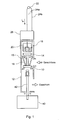
- the control device shown in FIG. 1 includes a safety valve 10, which in a valve body 12 is arranged to selectively open a gas inlet and to shut down.
- the safety valve 10 is fixed via a plunger with a metal disc fourteenth connected so that the metal plate 14 and thus also the safety valve 10th by a spring 16 with corresponding spring force in a gas inlet biased closing position.
- the controller further includes a Magnetic force generating device 18, which in particular an electromagnet 20th contains. The electromagnet 20 generates at a current flow, a magnetic force, which the metal plate 14 attracts.
- thermocouple 22 is provided, which in the region of a gas flame (not shown in the figure) of the gas burner is positioned and over electrical connection lines 24a, 24b with the magnetic force generating device 18th connected is. At a heat influence caused by the gas flame, i. at Existing gas flame produces the thermocouple 22 in a known manner Thermoelectric voltage, which is the magnetic force generating device 18 is supplied. Due to this thermoelectric voltage flows through the windings of the electromagnet 20th the magnetic force generating device 18 corresponding to the thermoelectric voltage Thermostrom, which generates a magnetic force with the metal plate 14th is attracted.
- the magnetic force generating device 18 and the spring 16 are selected such that the magnetic force generated by the thermo-current I th from the electromagnet 20 may hold the metal plate 14 in contact with the electromagnet 20 when the metal plate 14 is already in contact or very close to the electromagnet 20, but the metal plate 14 but not from its rest position, in which the safety valve 10 blocks the gas inlet, can put out.
- thermocouple 22 To open the safety valve 10 is a corresponding ignition switch 40th provided, which in a manual operation via a plunger 42 the Safety valve 10 moves against the spring force of the spring 16 in an open position and simultaneously ignited a gas flame in a known manner. With inflamed flame the thermocouple 22 generates a corresponding thermal current through the Magnetic force generating device 18, so that the metal plate 14 also after the Letting go of the ignition switch 40 in contact with the electromagnet 20 remains and thereby the gas inlet through the safety valve 10 remains open, as above described.
- the gas inlet is automatically shut off again by the safety valve 10 when the gas flame extinguishes, since in this case the thermocouple 22 does not generate a thermo- current I th and therefore the electromagnet 20 of the magnetic-force generating device 18 no longer generates any magnetic force acting on the metal disk 14, so that the safety valve 10 is moved by the spring 16 in its closed position.
- the safety valve 10 can be opened in this case only by a repeated actuation of the ignition switch 40, but not only by the generation of a thermo-current from the thermocouple 22 again.
- thermocouple 22 and the magnetic force generating device 18th there is also a shutdown device 26.
- this shutdown device 26th the gas inlet can be locked automatically after a preset period of time and thus, for example, a cooking process to be ended. So that shown in Fig. 1 Control device also for off-grid gas burners or gas stoves is suitable, this shutdown device 26 must meet special requirements. The following will be described with reference to Figs. 2A and 2B, and Figs. 3A and 3B, respectively Embodiments of a suitable shutdown device 26 according to the present invention Invention explained in more detail.
- the illustrated in Figs. 2A and 2B and via a breaker port 27 in The shutdown device 26 connected to the thermal circuit contains in particular one off-grid operated electronic timer 28 and one of the timer 28th controlled switching element 32a in the form of a bistable relay (as energy-saving Switching element).
- the off-line timer 28 also includes a energy-saving LCD display as display device 30 and batteries / accumulators 34 and / or another energy dispenser (e.g., a gold cap capacitor) Power supply.
- the timer 28 may also be provided with at least one solar cell (not shown) for charging the accumulators 34 or the other Energy storage (gold cap) be provided.
- the contact of the bistable relay 32a is connected in series with the thermocouple 22 between the thermocouple 22 and the magnetic force generating device 18.
- a suitable capacitance 36 is also connected in series with the winding of the bistable relay 32a.
- the relay 32a is normally in its closed position, so that the thermal current I th generated by the thermal element 22 because of the gas flame 23 is allowed to flow by the magnetic force generating means 18th
- the timer 28 outputs to the bistable relay 32 a control signal which opens the relay 32 a and thus the supply of the thermo-current I th to the magnetic force generating means 18 interrupts.
- the supply of the control signal must be made only briefly, for example, for about 1 to 2 seconds, which requires only a short-term energy needs.
- the interruption of the Thermostromzucht to the magnetic force generating device 18 and the generation of the magnetic force is interrupted by the electromagnet 20 so that the metal plate 14 and thus the safety valve 10 are moved by the spring 16 in its rest position, in which the gas inlet through the safety valve 10th Is blocked. Even if after the temporary opening of the relay 32a this is closed again and then possibly again a thermo-current I th flows through the magnetic force generating means 18, the safety valve 10 is not opened because the magnetic force generated by the electromagnet 20 by means of the thermo-current not to attraction the metal disk 14 is sufficient from the remote from the electromagnet 20 rest position.
- the short-term opening of the relay 32a is sized so that the opening period the time for the metal disc 14 to fall off the electromagnet 20 plus a corresponds to certain security surcharge. Overall, about 1 way usual way sufficient for 2 seconds. By the short-term opening of the relay 32a through the Timer 28, the gas burner is thus switched off safely.
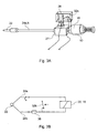
- FIGS. 3A and 3B An alternative embodiment of the shutdown device 26 for the illustrated in Fig. 1 Control device is illustrated in FIGS. 3A and 3B.
- the field effect transistor 32b is parallel to the Thermocouple 22 between the thermocouple 22 and the Magnetic force generating device 18 connected.
- a suitable resistor 38 in the Thermostrom connected a suitable resistor 38.
- the timer 28 sends a control signal to the field effect transistor 32b to put this from its normally open, ie locked state in a closed, ie conductive state, so that at least a portion of the thermo-current generated by the thermocouple thermistor I th flows through the field effect transistor 32b.
- the proportion of the current flowing through the magnetic force generating means 18 thermo-current is sufficiently reduced, so that the magnetic force is no longer sufficient to hold the metal disc 14 against the force of the spring 16 to the electromagnet 20.
- the safety valve 10 is closed. Also in this case, a short-term closing of the field effect transistor 32b and thus a short-term reduction of the current flowing through the magnetic force generating device 18 thermoelectric current to close the safety valve 10 is sufficient.
- a Forming switching module which directly on the connecting lines 24a, 24b between the thermocouple 22 and the magnetic force generating means 18 is arranged. In this way, long leads are avoided due to the low impedance of the thermal circuit would make a relevant size and thus the Functionality of the switching element 32b would be detrimental.
- the remaining structure of the shutdown device 26 of the second embodiment corresponds to that of the first embodiment, so that a repeated Description of the same can be dispensed with.
- the controller further includes a device for monitoring the State of charge of the battery or the accumulator. Is the state of charge so far dropped, that a safe shutdown of the gas supply can no longer be guaranteed could, then the entry of a shutdown program in the timer is blocked.
- the inventive Control device especially for use with mains-independent gas burners / gas stoves is formed, in which, of course, the built-in Switch-off device has no power supply from the mains.
- the Switch-off device of the control device according to the invention is therefore distinguished through the use of energy-saving components and an energy-saving Structure out, which only a short time a small amount of energy to close of the safety valve.
Landscapes
- Engineering & Computer Science (AREA)
- Chemical & Material Sciences (AREA)
- Combustion & Propulsion (AREA)
- Mechanical Engineering (AREA)
- General Engineering & Computer Science (AREA)
- Control Of Combustion (AREA)
Applications Claiming Priority (4)
| Application Number | Priority Date | Filing Date | Title |
|---|---|---|---|
| DE102004006666 | 2004-02-11 | ||
| DE102004006666 | 2004-02-11 | ||
| DE102004007310A DE102004007310B4 (de) | 2004-02-11 | 2004-02-14 | Steuereinrichtung für einen netzunabhängigen Gasbrenner |
| DE102004007310 | 2004-02-14 |
Publications (1)
| Publication Number | Publication Date |
|---|---|
| EP1564487A2 true EP1564487A2 (fr) | 2005-08-17 |
Family
ID=34702132
Family Applications (1)
| Application Number | Title | Priority Date | Filing Date |
|---|---|---|---|
| EP05002350A Withdrawn EP1564487A2 (fr) | 2004-02-11 | 2005-02-04 | Dispositif de commande pour un brûleur à gaz indépendant du réseau |
Country Status (1)
| Country | Link |
|---|---|
| EP (1) | EP1564487A2 (fr) |
Cited By (4)
| Publication number | Priority date | Publication date | Assignee | Title |
|---|---|---|---|---|
| EP2439434A1 (fr) * | 2010-10-07 | 2012-04-11 | Truma Gerätetechnik GmbH & Co. KG | Soupape avec un insert magnétique |
| ES2542254A1 (es) * | 2014-02-03 | 2015-08-03 | Bsh Electrodomésticos España, S.A. | Disposición de quemadores de gas, punto de cocción, y cocina |
| EP3279565A1 (fr) | 2016-08-03 | 2018-02-07 | Mamur Teknoloji Sistemleri Sanayi Anonim Sirketi | Unité de commande qui coupe automatiquement de gaz en cas de panne de courant |
| IT201700027214A1 (it) * | 2017-03-13 | 2018-09-13 | Castfutura Spa | Termocoppia di commando di organi di controllo dell’alimentazione di gas, sistema di controllo dell’alimentazione di gas e metodo per il controllo degli organi di controllo dell’alimentazione di gas |
-
2005
- 2005-02-04 EP EP05002350A patent/EP1564487A2/fr not_active Withdrawn
Cited By (6)
| Publication number | Priority date | Publication date | Assignee | Title |
|---|---|---|---|---|
| EP2439434A1 (fr) * | 2010-10-07 | 2012-04-11 | Truma Gerätetechnik GmbH & Co. KG | Soupape avec un insert magnétique |
| ES2542254A1 (es) * | 2014-02-03 | 2015-08-03 | Bsh Electrodomésticos España, S.A. | Disposición de quemadores de gas, punto de cocción, y cocina |
| WO2015114496A1 (fr) * | 2014-02-03 | 2015-08-06 | BSH Hausgeräte GmbH | Système de brûleurs à gaz, zone de cuisson et cuisinière |
| EP3279565A1 (fr) | 2016-08-03 | 2018-02-07 | Mamur Teknoloji Sistemleri Sanayi Anonim Sirketi | Unité de commande qui coupe automatiquement de gaz en cas de panne de courant |
| IT201700027214A1 (it) * | 2017-03-13 | 2018-09-13 | Castfutura Spa | Termocoppia di commando di organi di controllo dell’alimentazione di gas, sistema di controllo dell’alimentazione di gas e metodo per il controllo degli organi di controllo dell’alimentazione di gas |
| WO2018167614A1 (fr) * | 2017-03-13 | 2018-09-20 | Castfutura S.P.A. | Thermocouple d'entraînement d'éléments de commande d'alimentation en gaz, système de commande d'alimentation en gaz et procédé de commande d'éléments de commande d'alimentation en gaz |
Similar Documents
| Publication | Publication Date | Title |
|---|---|---|
| DE4026110A1 (de) | Vorrichtung zur regelung und bedienung einer mischwasserbereitungsanlage | |
| EP2218840A1 (fr) | Armature sanitaire dotée d'une commande de joystick | |
| CH632579A5 (de) | Vorrichtung zum steuern des betriebs eines gasbrenners und verwendung derselben. | |
| DE3411965C2 (fr) | ||
| DE3133686C2 (fr) | ||
| EP1564487A2 (fr) | Dispositif de commande pour un brûleur à gaz indépendant du réseau | |
| DE19752472A1 (de) | Anordnung und Verfahren zum Steuern einer Heizvorrichtung für Gaskochmulden | |
| DE10309469B3 (de) | Gasregelarmatur | |
| DE102004007310B4 (de) | Steuereinrichtung für einen netzunabhängigen Gasbrenner | |
| DE10305928B3 (de) | Verfahren und Schaltungsanordnung zum Zünden eines Gasstromes | |
| DE19723653B4 (de) | Sicherheitsabschaltvorrichtung für Gasverbrennungsgeräte | |
| EP1592922B1 (fr) | Procede et dispositif pour enflammer un courant gazeux | |
| DE2917584C2 (fr) | ||
| EP1505344B1 (fr) | Dispositif électrique pour l'arrêt d'une flamme de plaque chauffante faisant partie d'un ensemble de plusieurs plaques chauffantes à gaz | |
| DE1551943A1 (de) | Vorrichtung zur thermostatischen Steuerung einer Heizanlage | |
| DE2423974A1 (de) | Schaltungsanordnung eines feuerungsautomaten | |
| DE3041644C2 (de) | Zünd- und Überwachungseinrichtung | |
| CH347497A (de) | Verfahren und Vorrichtung zum Anzünden und Sichern eines Brenners | |
| DE2425545A1 (de) | Schaltungsanordnung eines feuerungsautomaten | |
| AT212165B (de) | Schaltvorrichtung für mit strömendem Brennstoff betriebene Heizungen, insbesondere Fahrzeugheizungen | |
| DE2617259B2 (de) | Steuer- und Überwachungsvorrichtung für öl- oder Gasbrenner | |
| DE3607731A1 (de) | Schaltung zur steuerung einer brennstoffbeheizten waermequelle | |
| DE1109624B (de) | Sicherungs- und Zuendvorrichtung fuer einen Brenner | |
| DE1451594A1 (de) | Steuer- und UEberwachungsvorrichtung fuer Brenneranlagen | |
| DE1295783B (de) | Elektrische Steuereinrichtung fuer mit stroemendem Brennstoff betriebene Brenner |
Legal Events
| Date | Code | Title | Description |
|---|---|---|---|
| PUAI | Public reference made under article 153(3) epc to a published international application that has entered the european phase |
Free format text: ORIGINAL CODE: 0009012 |
|
| AK | Designated contracting states |
Kind code of ref document: A2 Designated state(s): AT BE BG CH CY CZ DE DK EE ES FI FR GB GR HU IE IS IT LI LT LU MC NL PL PT RO SE SI SK TR |
|
| AX | Request for extension of the european patent |
Extension state: AL BA HR LV MK YU |
|
| STAA | Information on the status of an ep patent application or granted ep patent |
Free format text: STATUS: THE APPLICATION IS DEEMED TO BE WITHDRAWN |
|
| 18D | Application deemed to be withdrawn |
Effective date: 20120901 |