EP1564519A1 - Minenschutz-Fahrzeugsystem - Google Patents
Minenschutz-Fahrzeugsystem Download PDFInfo
- Publication number
- EP1564519A1 EP1564519A1 EP04029760A EP04029760A EP1564519A1 EP 1564519 A1 EP1564519 A1 EP 1564519A1 EP 04029760 A EP04029760 A EP 04029760A EP 04029760 A EP04029760 A EP 04029760A EP 1564519 A1 EP1564519 A1 EP 1564519A1
- Authority
- EP
- European Patent Office
- Prior art keywords
- vehicle according
- vehicle
- module
- building block
- cabin
- Prior art date
- Legal status (The legal status is an assumption and is not a legal conclusion. Google has not performed a legal analysis and makes no representation as to the accuracy of the status listed.)
- Granted
Links
- 239000002360 explosive Substances 0.000 claims description 7
- 239000000725 suspension Substances 0.000 claims description 6
- 239000000463 material Substances 0.000 claims description 3
- 230000001681 protective effect Effects 0.000 claims description 3
- 229910000831 Steel Inorganic materials 0.000 claims description 2
- 229910052782 aluminium Inorganic materials 0.000 claims description 2
- XAGFODPZIPBFFR-UHFFFAOYSA-N aluminium Chemical compound [Al] XAGFODPZIPBFFR-UHFFFAOYSA-N 0.000 claims description 2
- 239000010959 steel Substances 0.000 claims description 2
- 230000000694 effects Effects 0.000 description 5
- 238000000926 separation method Methods 0.000 description 4
- 238000004880 explosion Methods 0.000 description 3
- 238000010276 construction Methods 0.000 description 2
- 230000002411 adverse Effects 0.000 description 1
- 230000005540 biological transmission Effects 0.000 description 1
- 238000005422 blasting Methods 0.000 description 1
- 230000000295 complement effect Effects 0.000 description 1
- 230000008878 coupling Effects 0.000 description 1
- 238000010168 coupling process Methods 0.000 description 1
- 238000005859 coupling reaction Methods 0.000 description 1
- 238000013016 damping Methods 0.000 description 1
- 238000001514 detection method Methods 0.000 description 1
- 230000009189 diving Effects 0.000 description 1
- 238000011156 evaluation Methods 0.000 description 1
- 230000009931 harmful effect Effects 0.000 description 1
- 229910052751 metal Inorganic materials 0.000 description 1
- 239000002184 metal Substances 0.000 description 1
- 230000035939 shock Effects 0.000 description 1
Images


Classifications
-
- F—MECHANICAL ENGINEERING; LIGHTING; HEATING; WEAPONS; BLASTING
- F41—WEAPONS
- F41H—ARMOUR; ARMOURED TURRETS; ARMOURED OR ARMED VEHICLES; MEANS OF ATTACK OR DEFENCE, e.g. CAMOUFLAGE, IN GENERAL
- F41H7/00—Armoured or armed vehicles
- F41H7/02—Land vehicles with enclosing armour, e.g. tanks
- F41H7/04—Armour construction
- F41H7/042—Floors or base plates for increased land mine protection
-
- F—MECHANICAL ENGINEERING; LIGHTING; HEATING; WEAPONS; BLASTING
- F41—WEAPONS
- F41H—ARMOUR; ARMOURED TURRETS; ARMOURED OR ARMED VEHICLES; MEANS OF ATTACK OR DEFENCE, e.g. CAMOUFLAGE, IN GENERAL
- F41H7/00—Armoured or armed vehicles
- F41H7/02—Land vehicles with enclosing armour, e.g. tanks
-
- F—MECHANICAL ENGINEERING; LIGHTING; HEATING; WEAPONS; BLASTING
- F41—WEAPONS
- F41H—ARMOUR; ARMOURED TURRETS; ARMOURED OR ARMED VEHICLES; MEANS OF ATTACK OR DEFENCE, e.g. CAMOUFLAGE, IN GENERAL
- F41H7/00—Armoured or armed vehicles
- F41H7/02—Land vehicles with enclosing armour, e.g. tanks
- F41H7/04—Armour construction
- F41H7/048—Vehicles having separate armoured compartments, e.g. modular armoured vehicles
Definitions
- the invention relates to a vehicle with protection against the effect of a Landmine, in particular an armored wheeled vehicle, for the protection of persons as well as the vehicle body in armored vehicles in total against the effect of the explosion of mines laid on or in the ground are.
- These vehicles usually have a smooth underbody and chassis as high a ground clearance as possible between the subfloor and the ground, that of appropriately trained wheel or track suspensions is ensured so the vehicle can move as freely as possible in the terrain.
- the explosive pressure of the exploding under the vehicle mine acts the relatively large vehicle or tub floor, deformed and damaged this and can cause significant damage in the vehicle.
- DE 31 19 786 From DE 31 19 786 it is known to install for protection against mines on the underside of the vehicle planar armor elements.
- DE 196 31 715 the vehicle floor is equipped with a wedge-shaped trained to the bottom deflector, wherein the deflector can also be equipped with a gas generator for support from the inside and counteracting the explosion.
- deformation bodies are attached to the vehicle floor, to reduce the pressure effect of mines on the vehicle.
- a basic housing is as a central supporting unit trained and takes on the engine, has spaces as a payload and serves as a passenger compartment. Below the basic housing is a subframe attached, the one between engine with manual transmission and the wheels arranged intermediate gear receives.
- a mine protection device in particular known for wheeled vehicles, in which from a detected shockwave / Structure-borne sound wave or blast wave a detection signal from an ignition and evaluation unit is detected, which is connected to a pyrotechnic separation element is and to a separation of the wheel assembly and the wheel of the vehicle structure leads.
- the pyrotechnic separation of the support structure can by a Cutting charge or by suitable designs of the separation point by means of pyrotechnic Disconnect screws done.
- the object of the invention is to provide a generic protection system, that an improvement of the protective effect with a simple and robust construction guaranteed for the crew of an armored vehicle. It should after Possibility of highest possible mine protection, primarily against blast mines, by combination all protection options are realized in a vehicle concept.
- the vehicle is divided into several components, for example three, divided, which are detachably connected to each other.
- This vehicle sits down from a middle building block, the so-called main building block, as well as a Front and rear module together.
- Rear and front part are at the middle Module flanged or releasably secured by means of explosive bolts.
- the explosive bolts are ignited by means of a built-in charge and can be blasted off become.
- the connection of the blocks with predetermined breaking points having Bolt is also possible.
- the wheel axles are placed so that they do not lie under the crew compartment.
- the actual crew compartment is used as a cabin or protective cell in the vehicle body, the main component, suspended and decoupled in vibration.
- the support structure is held plastically deformable and the V-shaped underbody is built without breakthroughs such as doors. It takes place So an elastic suspension in the roof area of the main building block, the plastically deformable, energy-absorbing, thin-walled hollow profiles.
- the steering and a drive motor accommodated In the front module are in addition to the front axle, the steering and a drive motor accommodated.
- the tail module can also be next to the rear axle a drive motor included. This has the advantage of having a front engine and a Rear engine can be operated simultaneously, allowing a redundant drive created and a residual mobility can be ensured.
- One within the main building block between the V-shaped bottom of the support structure and the (bottom) flattened cabin resulting space can drive shaft and / or cable.
- the advantages of the inventive design of the vehicle are mainly in the high mine protection for the crew. This is achieved by the V-shaped Floor, the space above the wheels (for example, higher Wheel arches, missing wheel arches), the plastically deformable hollow profiles for the Support structure, the double-walled shell made of thin sheet steel, one Security cell for the crew made of thick-walled light metal and the coupling the safety cell in the roof area of the support structure, individually, in parts or in total.
- the building blocks are designed so that mine blasting is as small as possible have harmful effects.
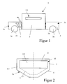
- a vehicle 4 shown in FIG. 1 from the side has a front module 1, here also referred to as engine block, with a wheel axle 1a and a wheel 1b, a main building block 2, here also referred to as crew room building block, and a Heckbaustein 3 with a wheel axle 3a and a wheel 3b.
- the wheel axles 1a, 3a are not us usual under the team room module 2 arranged here.
- Engine and tail module 1, 3 are flanged to the crew room module 2 or detachable by means of sketchy indicated bolt / explosive bolt 4a associated with this.
- the front module 1 has next to a not shown Steering a drive motor 1c on. Also in the Heckbaustein 3 can a Drive motor 3 are provided.
- the team room module 2 consists of an outer 2.1 and an inner Area 2.2.
- the outer area 2.1 is a trough 2.a and down V-shaped educated.
- the inner area 2.2, the actual crew room, is fully enclosed by a cabin or security cell 9, 11 and is in the outer part, the housing part 10, hung and at the upper edge of the outer Section 2.1 attached.
- the principle of the suspended cabin 9 is shown, this as a safety cell 9 suspended by means of elastic suspensions 8 in the housing part 10 is.
- the housing part 10 has a plastically deformable support structure on.
- the material of this cabin 9 is preferably aluminum to secondary splitter catch.
- FIG 4 is a bottom pointed security cell 11 and main building block 2 shown in the vehicle longitudinal direction.
- a vehicle door 16 in an open Position 12 and a closed position 14 shown.
- the door 16 becomes pivoted about a pivot bearing 15 with the direction of movement 13.
- the pivot bearing 15 or the hinges of the door 16 is at the bottom of the main block 2, preferably attached before the bevel.
- FIG. 5 shows an example vehicle 4 according to the invention with the building blocks Front module 1, main module 2 and rear module 3 shown.
- a mine In a mine explosion, a mine, not shown, first hits the wheel 1b or 3b, which can be detached and fly away upwards (clearance above Bikes). Then the whole front module 1 can tear off or even blasted off be by means of the explosive bolts, not shown. In doing so, the entire Axis 1a and the drive of vehicle 4 separately, without from below into the Main building block 2 to beat, since the building blocks 1, 2, 3 have vertical dividing lines.
- the residual pulse which then flows into the middle main module 2 is due to the double-walled construction in the lower area in deformation energy transformed. Thereafter, the impulse hits thin-walled supports in the upper area, who are diving together. The remaining residual pulse then hits on the elastic bearing or suspension 8 on the roof of the cabin 9, 11. There is the impulse already so long and flat that mechanical springs or similar used can be. The residual impulse that passes through these springs into the roof of the cabin 9, 11 flows, is muffled far enough not to hurt the crew anymore.
- V-shape of the support structure the thick wall the cabin, the possible redundancy of the drive components.
- front and / or rear building block 1, 3 beveled floors may have, which correspond to the bottom 6 of the main module 2.
Landscapes
- Engineering & Computer Science (AREA)
- General Engineering & Computer Science (AREA)
- Body Structure For Vehicles (AREA)
- Aiming, Guidance, Guns With A Light Source, Armor, Camouflage, And Targets (AREA)
- Emergency Protection Circuit Devices (AREA)
- Window Of Vehicle (AREA)
- Excavating Of Shafts Or Tunnels (AREA)
Abstract
Description
Die einfachste Vorkehrung ist die Auslegung des Wannenbodens mit einer Plattendicke, die gegen eine vorgegebene Minenansprengung sicher ist, wobei ein hohes Gewicht die Folge ist, was sich ungünstig auswirken kann.
Eine andere Möglichkeit liegt darin, die Bodenplatte einer Wanne mittels einer Sandwichplatte, die sich aus verschiedenen übereinanderliegenden Materialien aufbaut und die gegen eine vorgegebene Minenansprengung sicher ist, aufzubauen. Schließlich kann die Bodenstruktur aus übereinanderliegenden Platten und Hohlräumen, dabei auch zum Beispiel Luftschichten, ausgebildet sein, so dass die oberste Platte keine oder nur eine geringe Aufbeulung bei einer vorgegebenen Minenansprengung aufweist.
In der DE 196 31 715 ist der Fahrzeugboden mit einem keilförmig zum Boden ausgebildeten Deflektor ausgerüstet, wobei der Deflektor auch mit einem Gasgenerator ausgerüstet sein kann zur Abstützung von innen und Gegenwirkung gegen die Explosion.
- Figur 1:
- Seitenansicht eines Fahrzeugs
- Figur 2:
- Querschnitt einer Sicherheitszelle für die Besatzung
- Figur 3:
- Seitenansicht der aufgehängten Sicherheitszelle
- Figur 4:
- Querschnitt Sicherheitszelle mit Türprinzip
- Figur 5:
- Perspektivansicht eines Beispielfahrzeugs
- 1
- Front- bzw. Motorbaustein
- 1a
- Radachse
- 1b
- Rad
- 2
- Hauptbaustein, Mannschaftsraum- Baustein
- 2.1
- äußerer Bereich
- 2.2
- innerer Bereich
- 2.a
- Wanne
- 3
- Heckbaustein
- 3a
- Radachse
- 3b
- Rad
- 4
- Fahrzeug
- 4.a
- Bolzen / Sprengbolzen
- 5
- doppelwandiger Boden
- 6
- abgeschrägter Boden
- 7
- Hohlprofil
- 8
- elastische Aufhängung
- 9
- Sicherheitszelle
- 10
- Gehäuseteil
- 11
- Sicherheitszelle
- 12
- Tür - geschlossen
- 13
- Bewegungsrichtung
- 14
- Tür - geöffnet
- 15
- Drehlager
- 16
- Tür
Claims (16)
- Fahrzeug (4) mit Schutz gegen die Wirkung einer Landmine, insbesondere ein gepanzerten Radfahrzeug, bestehend aus mehreren Bausteinen (1, 2, 3) mittels Aufteilung und Unterteilung des Fahrzeugs (4), wobei die Bausteine wenigstens einen Hauptbaustein (2), einen Frontbaustein (1) und einen Heckbaustein (2) umfassen, die über Mittel (4a) lösbar miteinander verbunden sind, wobei Front- als auch Heckbaustein (1, 3) am Hauptbaustein (2) vorn oder hinten befestigt sind und Radachsen (1a, 3a) des Fahrzeugs (4) so platziert sind, dass sie sich nicht unter dem Hauptbaustein (2) befinden.
- Fahrzeug nach Anspruch 1, dadurch gekennzeichnet, dass die Mittel (4a) Bolzen, welche Sollbruchstellen aufweisen, und / oder Sprengbolzen, welche mittels einer eingebauten Ladung gezündet und abgesprengt werden können, sind.
- Fahrzeug nach Anspruch 1 oder 2, dadurch gekennzeichnet, dass ein Freiraum senkrecht nach oben über den Rädern (1b,3b) und den Radachsen (1a, 3a) eingehalten ist.
- Fahrzeug nach einem der vorgenannten Ansprüche, dadurch gekennzeichnet, dass der Hauptbaustein (2) einen V-förmigen Unterboden (6) besitzt.
- Fahrzeug nach einem der vorgenannten Ansprüche, dadurch gekennzeichnet, dass das Wannengehäuse (2a) doppelwandig ausgeführt ist und aus dünnem Stahlblech besteht.
- Fahrzeug nach Anspruch 5, dadurch gekennzeichnet, dass das Wannengehäuse (2a) aus Hohlprofilen (7) gebildet wird.
- Fahrzeug nach einem der vorgenannten Ansprüche, dadurch gekennzeichnet, dass der Hauptbaustein eine Kabine und/ oder Schutzzelle (9, 11) enthält, welche mittels elastischer Aufhängungen (8) im Gehäuseteil (10) eingehängt und schwingungsmäßig entkoppelt werden.
- Fahrzeug nach Anspruch 7, dadurch gekennzeichnet, dass das Gehäuseteil (10) eine plastisch deformierbare Tragstruktur aufweist.
- Fahrzeug nach einem der vorgenannten Ansprüche, dadurch gekennzeichnet, dass der Hauptbaustein (2) mit Türen (16) versehen ist, die in offener Position (12) heruntergeklappt sind und als Tritthilfe genutzt werden können.
- Fahrzeug nach einem der oben genannten Ansprüche, dadurch gekennzeichnet, dass der Frontbaustein (1) die Vorderachse (1a) und die Lenkung enthält.
- Fahrzeug nach Anspruch 10, dadurch gekennzeichnet, dass der Frontbaustein (1) einen Antriebsmotor (1c) enthält.
- Fahrzeug nach einem der Ansprüche 1 bis 11, dadurch gekennzeichnet, dass der Heckbaustein (3) die Hinterachse (3a) enthält.
- Fahrzeug nach Anspruch 12, dadurch gekennzeichnet, dass der Heckbaustein (3) einen Antriebsmotor (3c) enthält.
- Fahrzeug nach einem der Ansprüche 6 bis 13, dadurch gekennzeichnet, dass die Kabine (9, 11) aus dickwandigem, zähen Material, wie Aluminium besteht.
- Fahrzeug nach einem der Ansprüche 1 bis 14, dadurch gekennzeichnet, dass innerhalb des Hauptbausteins (2) zwischen dem V-förmigen Boden (6) der Tragstruktur und der unten abgeflachten Kabine (9, 11) ein Raum für die Antriebswelle oder für Kabel gebildet wird.
- Fahrzeug nach einem der vorgenannten Ansprüche 6 bis 15, dadurch gekennzeichnet, dass das Fahrzeug durch einfaches Aushängen der Kabine (9, 11) und Einhängen einer anderen Kabine (9, 11) in eine neue FahrzeugVersion umgerüstet werden kann.
Applications Claiming Priority (2)
| Application Number | Priority Date | Filing Date | Title |
|---|---|---|---|
| DE102004006819 | 2004-02-11 | ||
| DE102004006819A DE102004006819B4 (de) | 2004-02-11 | 2004-02-11 | Fahrzeug mit Schutz gegen die Wirkung einer Landmine |
Publications (2)
| Publication Number | Publication Date |
|---|---|
| EP1564519A1 true EP1564519A1 (de) | 2005-08-17 |
| EP1564519B1 EP1564519B1 (de) | 2010-02-17 |
Family
ID=34684014
Family Applications (1)
| Application Number | Title | Priority Date | Filing Date |
|---|---|---|---|
| EP04029760A Expired - Lifetime EP1564519B1 (de) | 2004-02-11 | 2004-12-16 | Minenschutz-Fahrzeugsystem |
Country Status (5)
| Country | Link |
|---|---|
| US (1) | US7594561B2 (de) |
| EP (1) | EP1564519B1 (de) |
| AT (1) | ATE458176T1 (de) |
| DE (2) | DE102004006819B4 (de) |
| ES (1) | ES2339446T3 (de) |
Cited By (8)
| Publication number | Priority date | Publication date | Assignee | Title |
|---|---|---|---|---|
| EP2589919A1 (de) * | 2011-11-03 | 2013-05-08 | FFG Flensburger Fahrzeugbaugesellschaft mbH | Gepanzertes minengefährdetes Fahrzeug |
| EP2373510A4 (de) * | 2008-12-29 | 2014-03-12 | Hal Tech Ltd | Verformbares modulares panzergefechtssystem |
| EP2264394A3 (de) * | 2009-06-19 | 2014-03-26 | Rheinmetall Landsysteme GmbH | Fahrzeug, insbesondere gepanzertes Fahrzeug mit einer die Besatzung des Fahrzeuges aufnehmenden Sicherheitszelle |
| WO2015058290A1 (en) * | 2013-10-23 | 2015-04-30 | 2040422 Ontario Inc. | Survivability capsule for armored vehicles |
| EP3179201A1 (de) * | 2015-12-08 | 2017-06-14 | BAE Systems PLC | Geteilter rumpf |
| WO2017098215A1 (en) * | 2015-12-08 | 2017-06-15 | Bae Systems Plc | Split hull |
| CN114537132A (zh) * | 2022-03-31 | 2022-05-27 | 重庆望江工业有限公司 | 防地雷车的主减速器安装结构 |
| IT202200005426A1 (it) * | 2022-03-18 | 2023-09-18 | Tosolini Mapimi | Telaio per un veicolo modulare |
Families Citing this family (46)
| Publication number | Priority date | Publication date | Assignee | Title |
|---|---|---|---|---|
| US7770506B2 (en) * | 2004-06-11 | 2010-08-10 | Bae Systems Tactical Vehicle Systems Lp | Armored cab for vehicles |
| IL162945A0 (en) * | 2004-07-08 | 2005-11-20 | Plasan Kibbutz Sasa | Truck cabin armor |
| DE202005006655U1 (de) * | 2005-04-12 | 2005-08-25 | Drehtainer Gmbh Spezial Container- Und Fahrzeugbau | Geschütztes Fahrzeug oder Schiff |
| DE102005055501B4 (de) * | 2005-11-18 | 2007-10-11 | Rheinmetall Landsysteme Gmbh | Vorrichtung zur Montage, Demontage und/oder Transport von Baugruppen eines sich aus diesen Baugruppen modular zusammensetzbaren Fahrzeuges |
| DE102006051870A1 (de) | 2005-11-18 | 2007-05-24 | Rheinmetall Landsysteme Gmbh | Gepanzertes Fahrzeug |
| DE102005055502B4 (de) * | 2005-11-18 | 2007-08-09 | Rheinmetall Landsysteme Gmbh | Baugruppen- und/oder Modul-Verbinder |
| US20070186762A1 (en) * | 2005-12-22 | 2007-08-16 | Blackwater Lodge And Training Center Llc | Armored vehicle with blast deflecting hull |
| US7849945B2 (en) * | 2006-02-24 | 2010-12-14 | Honda Motor Co., Ltd | Modular electric powertrain for a vehicle |
| US7357062B2 (en) * | 2006-04-11 | 2008-04-15 | Force Protection Industries, Inc. | Mine resistant armored vehicle |
| DE102006034689A1 (de) * | 2006-07-24 | 2008-01-31 | Rheinmetall Landsysteme Gmbh | Schutzeinrichtung für ein militärisches Fahrzeug, welches als Unterstützungsfahrzeug fungiert und alle pionier- und bergtechnischen Arbeiten ausführen kann |
| US20080173167A1 (en) * | 2006-09-15 | 2008-07-24 | Armor Holdings | Vehicular based mine blast energy mitigation structure |
| US20080066613A1 (en) * | 2006-09-15 | 2008-03-20 | Lockheed Martin Corporation | Perforated hull for vehicle blast shield |
| DE102007002576A1 (de) * | 2007-01-11 | 2008-07-17 | Rheinmetall Landsysteme Gmbh | Entkoppelte Pedaleinheit in einem minengeschützten, insbesondere militärischen Fahrzeug |
| DE102007060503A1 (de) | 2007-12-15 | 2009-06-25 | Rheinmetall Landsysteme Gmbh | Fahrwerkmodul für ein aus mehreren Modulen zusammensetzbares Radfahrzeug |
| DE102008019656A1 (de) * | 2008-04-18 | 2009-10-22 | Krauss-Maffei Wegmann Gmbh & Co. Kg | Militärisches Kraftfahrzeug |
| DE102008049145A1 (de) | 2008-09-26 | 2010-04-08 | Rheinmetall Landsysteme Gmbh | Vorrichtung zur lösbaren Verbindung von Baugruppenträgern eines sich aus Baugruppen modular zusammensetzbaren Kraftfahrzeuges |
| DE102008052072B4 (de) | 2008-10-17 | 2011-04-28 | Rheinmetall Landsysteme Gmbh | Kraftfahrzeug mit Allradantrieb |
| WO2010090661A1 (en) * | 2008-10-24 | 2010-08-12 | Alcoa Inc. | Blast energy absorption system |
| GB0822444D0 (en) * | 2008-12-10 | 2009-01-14 | Sloman Roger M | Vehicle stabilization |
| IL196456A0 (en) * | 2009-01-12 | 2009-12-24 | Shlomo Birger | Uderbelly of armord vehicle |
| US8033208B2 (en) * | 2009-04-10 | 2011-10-11 | Force Protection Technologies, Inc. | Mine resistant armored vehicle |
| US8146478B2 (en) * | 2009-04-10 | 2012-04-03 | Force Protection Technologies, Inc. | Mine resistant armored vehicle |
| GB2470052A (en) * | 2009-05-07 | 2010-11-10 | Ricardo Uk Ltd | Vehicle chassis, vehicle body and vehicle suspension |
| US8667880B1 (en) * | 2009-05-12 | 2014-03-11 | Granite Tactical Vehicles Inc. | Cabin for a Humvee vehicle |
| US20170052002A9 (en) * | 2009-05-12 | 2017-02-23 | Granite Tactical Vehicles Inc. | Moving sacrificial vehicle hull |
| US8656823B2 (en) * | 2009-06-05 | 2014-02-25 | Fox Factory, Inc. | Methods and apparatus for suspending a vehicle shield |
| IL202275A0 (en) | 2009-11-23 | 2010-11-30 | Plasan Sasa Ltd | A system for providing protection against an explosive threat |
| EP2325595A3 (de) | 2009-11-23 | 2014-04-30 | Plasan Sasa Ltd. | Bodenschutz |
| US8499677B2 (en) | 2009-11-30 | 2013-08-06 | General Dynamics Land Systems—Canada Corporation | W-shaped hull |
| US8584572B2 (en) * | 2009-12-18 | 2013-11-19 | Hardwire, Llc | Vehicle with structural vent channels for blast energy and debris dissipation |
| US8578834B2 (en) * | 2009-12-18 | 2013-11-12 | Hardwire, Llc | Vehicle with structural vent channels for blast energy and debris dissipation |
| US8146477B2 (en) | 2010-05-14 | 2012-04-03 | Force Protection Technologies, Inc. | System for protecting a vehicle from a mine |
| GB201008903D0 (en) * | 2010-05-27 | 2010-07-14 | Sloman Roger M | Vehicle stabilization |
| US8616617B2 (en) | 2010-10-25 | 2013-12-31 | BAE Systems Tactical Vehicle Systems L.P. | Lightweight blast resistant armored cab for vehicles |
| US8176832B1 (en) * | 2011-01-13 | 2012-05-15 | The United States Of America As Represented By The Secretary Of The Army | System and method for obstruction deflection |
| US20120239247A1 (en) * | 2011-03-16 | 2012-09-20 | General Dynamics Land Systems, Inc. | Systems and methods for active mitigation of sudden accelerative forces in vehicles |
| US9045014B1 (en) | 2012-03-26 | 2015-06-02 | Oshkosh Defense, Llc | Military vehicle |
| USD966958S1 (en) | 2011-09-27 | 2022-10-18 | Oshkosh Corporation | Grille element |
| DE102012107580C5 (de) * | 2012-08-17 | 2019-10-10 | Krauss-Maffei Wegmann Gmbh & Co. Kg | Vorrichtung und Verfahren zum Koppeln von einem Anbaugerät an einem Fahrzeug |
| DE102013007227A1 (de) | 2013-04-26 | 2014-11-13 | Rheinmetall Landsysteme Gmbh | Fahrzeug |
| US20160356586A1 (en) * | 2015-06-02 | 2016-12-08 | Fast Brass, Llc | Shell retaining assembly |
| EP3280676B1 (de) | 2016-04-08 | 2018-11-07 | Oshkosh Corporation | Niveauregulierungssystem für ein lift-gerät |
| US20190310055A1 (en) * | 2018-04-09 | 2019-10-10 | Pratt & Miller Engineering and Fabrication, Inc. | Blast deflector |
| US10745065B2 (en) * | 2018-04-16 | 2020-08-18 | Howe & Howe Inc. | Vehicle with pneumatically suspended operator compartment |
| EP4175843A4 (de) * | 2020-07-01 | 2024-08-07 | Magna International Inc | Modulare fahrzeugstruktur |
| DE102022103396A1 (de) * | 2022-02-14 | 2023-08-17 | Rheinmetall Landsysteme Gmbh | Anordnung und geschütztes Fahrzeug |
Citations (9)
| Publication number | Priority date | Publication date | Assignee | Title |
|---|---|---|---|---|
| US4031807A (en) * | 1974-09-20 | 1977-06-28 | Societe Anonyme Secmafer | Armoured assault car |
| US4280393A (en) * | 1978-04-14 | 1981-07-28 | Creusot-Loire | Light weight armored vehicle |
| DE3119786A1 (de) | 1981-05-19 | 1982-12-23 | Harry 7311 Hochdorf Apprich | Vorrichtung zur sicherung von flaechengebilden gegen die wirkung von sprengkoerpern |
| DE3206794A1 (de) * | 1982-02-25 | 1983-09-01 | Hermann Dr.-Ing. 3302 Cremlingen Klaue | Gepanzertes kampffahrzeug |
| DE19631715A1 (de) | 1996-08-06 | 1998-02-12 | Bundesrep Deutschland | Schutzsystem für Fahrzeuge gegen Minen |
| DE19653283C1 (de) | 1996-12-20 | 1998-06-25 | Mak System Gmbh | Panzerfahrzeug |
| DE19619865C2 (de) | 1996-05-17 | 1999-07-29 | Mak System Gmbh | Umrüstbares straßen- und geländegeeignetes Fahrzeug |
| DE19941928C2 (de) | 1999-09-03 | 2002-10-31 | Rheinmetall Landsysteme Gmbh | Vorrichtung zum Schutz gegen die Wirkung einer Landmine |
| DE10256918A1 (de) | 2002-12-05 | 2004-07-15 | Herding Gmbh Filtertechnik | Verfahren zum Klären von Abwasser unter Bildung von Überschussschlamm und entsprechende Abwasser-Kläranlage |
Family Cites Families (38)
| Publication number | Priority date | Publication date | Assignee | Title |
|---|---|---|---|---|
| US540156A (en) * | 1895-05-28 | Sheep-shears | ||
| US2716040A (en) * | 1949-01-26 | 1955-08-23 | Barenyi Bela | Motor vehicle having hinged end sections and attached lifting means |
| DE2430913A1 (de) | 1974-06-27 | 1976-01-08 | Jourdan Klaus Dipl Ing | Knickgelenktes panzerbares bzw. gepanzertes radfahrzeug |
| FR2281263A1 (fr) * | 1974-08-08 | 1976-03-05 | Secmafer Sa | Engin tous terrains |
| BE843531A (fr) * | 1976-06-29 | 1984-05-17 | Acec | Engin blindé auto-propulsé. |
| US4351558A (en) * | 1979-04-23 | 1982-09-28 | Mueller Frederick N | Truck body construction |
| JPS5951472B2 (ja) * | 1979-11-16 | 1984-12-14 | トヨタ自動車株式会社 | 組立式自動車 |
| US4492282A (en) * | 1980-08-28 | 1985-01-08 | Cadillac Gage Company | Six-wheel armored vehicle |
| US4676545A (en) * | 1981-07-06 | 1987-06-30 | Bonfilio Paul F | Modular chassis for land, sea and air vehicles |
| US4422685A (en) * | 1981-07-06 | 1983-12-27 | Bonfilio Paul F | Modular chassis and body for motor vehicles |
| FR2510737A1 (fr) | 1981-08-03 | 1983-02-04 | Fives Cail Babcock | Vehicule blinde de reconnaissance et de combat |
| EP0278479B1 (de) * | 1987-02-10 | 1993-05-12 | Nissan Motor Co., Ltd. | Fahrzeugbau, insbesondere Rahmen |
| GB8709125D0 (en) * | 1987-04-15 | 1987-05-20 | Siren A O | All-terrain hydrofoil train |
| US4842326A (en) * | 1987-05-08 | 1989-06-27 | John A. DiVito | Motor vehicles with interchangeable functional body modules |
| DE3719289C1 (en) * | 1987-06-10 | 1988-12-08 | Bundesrep Deutschland | Small combat vehicle system, configured in a modular manner, for wheeled or tracked vehicles (track-laying vehicles |
| US5176213A (en) * | 1987-12-09 | 1993-01-05 | Aisin Aw Co., Ltd. | Driving force distribution system for hybrid vehicles |
| US5245738A (en) * | 1988-09-19 | 1993-09-21 | Tini Alloy Company | Method for securing together and non-explosively separating multiple components |
| US5401056A (en) * | 1994-03-11 | 1995-03-28 | Eastman; Clayton | Modular vehicle constructed of front, rear and center vehicular sections |
| US5866839A (en) | 1994-03-21 | 1999-02-02 | Ohayon; Shalom | High performance armor protection system for tank crews and fighting vehicles |
| US5558588A (en) * | 1995-02-16 | 1996-09-24 | General Motors Corporation | Two-mode, input-split, parallel, hybrid transmission |
| US5738378A (en) * | 1996-04-01 | 1998-04-14 | Yazejian; Raymond V. | Safety vehicle |
| JP3861321B2 (ja) | 1996-05-02 | 2006-12-20 | トヨタ自動車株式会社 | ハイブリッド車 |
| US5663520A (en) * | 1996-06-04 | 1997-09-02 | O'gara-Hess & Eisenhardt Armoring Co. | Vehicle mine protection structure |
| US5934397A (en) * | 1997-01-28 | 1999-08-10 | Schaper; Douglas | Modular land vehicle |
| US5886839A (en) * | 1997-05-06 | 1999-03-23 | Arnone; Guido A. | Toy periscope mask for playing aquatic games |
| DE19756683C1 (de) * | 1997-12-19 | 1999-06-02 | Mak System Gmbh | Fahrantrieb für Kettenfahrzeuge |
| US7007761B1 (en) * | 1999-05-21 | 2006-03-07 | Johnson Iv John J | Emergency response vehicle |
| DE10003823C2 (de) * | 2000-01-28 | 2002-06-06 | Rheinmetall Landsysteme Gmbh | Vorrichtung zum Schutz der Besatzung eines militärischen Fahrzeuges |
| US6363830B1 (en) * | 2000-03-06 | 2002-04-02 | The United States Of America As Represented By The Secretary Of The Army | Door structure for mine protection |
| US6435071B1 (en) | 2000-10-26 | 2002-08-20 | John Bruce Campbell | Vehicle for traveling through hostile environments |
| DE10117575A1 (de) * | 2001-04-07 | 2002-10-10 | Krauss Maffei Wegmann Gmbh & C | Einrichtung zum Schutz der Besatzung eines militärischen Fahrzeugs bei Minenexplosion |
| DE10134394B4 (de) * | 2001-07-14 | 2004-02-12 | Rheinmetall Landsysteme Gmbh | Minenschutzboden für ein Panzerfahrzeug |
| JP4029592B2 (ja) * | 2001-09-05 | 2008-01-09 | 株式会社日立製作所 | 補助駆動装置およびこれを搭載した自動車 |
| US6817655B2 (en) * | 2002-06-18 | 2004-11-16 | Dana Corporation | Modular body and frame assembly for a vehicle |
| DE10233274A1 (de) * | 2002-07-23 | 2004-02-05 | Krauss-Maffei Wegmann Gmbh & Co.Kg | Aus Einzelsegmenten aufgebautes gepanzertes Radfahrzeug |
| DE10259918B4 (de) * | 2002-12-20 | 2005-06-23 | Rheinmetall Landsysteme Gmbh | Minenschutzeinrichtung, insbesondere für Radfahrzeuge |
| US6896319B1 (en) * | 2003-12-01 | 2005-05-24 | General Motors Corporation | Vehicle modular body and method of assembly thereof |
| DE102004026237A1 (de) * | 2004-02-11 | 2005-11-10 | Rheinmetall Landsysteme Gmbh | Fahrzeug mit Schutz gegen die Wirkung einer Landmine |
-
2004
- 2004-02-11 DE DE102004006819A patent/DE102004006819B4/de not_active Expired - Fee Related
- 2004-12-16 EP EP04029760A patent/EP1564519B1/de not_active Expired - Lifetime
- 2004-12-16 ES ES04029760T patent/ES2339446T3/es not_active Expired - Lifetime
- 2004-12-16 AT AT04029760T patent/ATE458176T1/de active
- 2004-12-16 DE DE502004010766T patent/DE502004010766D1/de not_active Expired - Lifetime
-
2005
- 2005-02-11 US US11/055,029 patent/US7594561B2/en not_active Expired - Lifetime
Patent Citations (9)
| Publication number | Priority date | Publication date | Assignee | Title |
|---|---|---|---|---|
| US4031807A (en) * | 1974-09-20 | 1977-06-28 | Societe Anonyme Secmafer | Armoured assault car |
| US4280393A (en) * | 1978-04-14 | 1981-07-28 | Creusot-Loire | Light weight armored vehicle |
| DE3119786A1 (de) | 1981-05-19 | 1982-12-23 | Harry 7311 Hochdorf Apprich | Vorrichtung zur sicherung von flaechengebilden gegen die wirkung von sprengkoerpern |
| DE3206794A1 (de) * | 1982-02-25 | 1983-09-01 | Hermann Dr.-Ing. 3302 Cremlingen Klaue | Gepanzertes kampffahrzeug |
| DE19619865C2 (de) | 1996-05-17 | 1999-07-29 | Mak System Gmbh | Umrüstbares straßen- und geländegeeignetes Fahrzeug |
| DE19631715A1 (de) | 1996-08-06 | 1998-02-12 | Bundesrep Deutschland | Schutzsystem für Fahrzeuge gegen Minen |
| DE19653283C1 (de) | 1996-12-20 | 1998-06-25 | Mak System Gmbh | Panzerfahrzeug |
| DE19941928C2 (de) | 1999-09-03 | 2002-10-31 | Rheinmetall Landsysteme Gmbh | Vorrichtung zum Schutz gegen die Wirkung einer Landmine |
| DE10256918A1 (de) | 2002-12-05 | 2004-07-15 | Herding Gmbh Filtertechnik | Verfahren zum Klären von Abwasser unter Bildung von Überschussschlamm und entsprechende Abwasser-Kläranlage |
Cited By (10)
| Publication number | Priority date | Publication date | Assignee | Title |
|---|---|---|---|---|
| EP2373510A4 (de) * | 2008-12-29 | 2014-03-12 | Hal Tech Ltd | Verformbares modulares panzergefechtssystem |
| EP2264394A3 (de) * | 2009-06-19 | 2014-03-26 | Rheinmetall Landsysteme GmbH | Fahrzeug, insbesondere gepanzertes Fahrzeug mit einer die Besatzung des Fahrzeuges aufnehmenden Sicherheitszelle |
| EP2589919A1 (de) * | 2011-11-03 | 2013-05-08 | FFG Flensburger Fahrzeugbaugesellschaft mbH | Gepanzertes minengefährdetes Fahrzeug |
| WO2013064258A1 (de) * | 2011-11-03 | 2013-05-10 | Ffg Flensburger Fahrzeugbaugesellschaft Mbh | Gepanzertes, minengefährdetes fahrzeug |
| AU2012331437B2 (en) * | 2011-11-03 | 2016-04-14 | Ffg Flensburger Fahrzeugbau Gesellschaft Mbh | Armoured, mine-endangered vehicle |
| WO2015058290A1 (en) * | 2013-10-23 | 2015-04-30 | 2040422 Ontario Inc. | Survivability capsule for armored vehicles |
| EP3179201A1 (de) * | 2015-12-08 | 2017-06-14 | BAE Systems PLC | Geteilter rumpf |
| WO2017098215A1 (en) * | 2015-12-08 | 2017-06-15 | Bae Systems Plc | Split hull |
| IT202200005426A1 (it) * | 2022-03-18 | 2023-09-18 | Tosolini Mapimi | Telaio per un veicolo modulare |
| CN114537132A (zh) * | 2022-03-31 | 2022-05-27 | 重庆望江工业有限公司 | 防地雷车的主减速器安装结构 |
Also Published As
| Publication number | Publication date |
|---|---|
| US20050257679A1 (en) | 2005-11-24 |
| DE102004006819A1 (de) | 2005-09-08 |
| DE102004006819B4 (de) | 2007-01-04 |
| ATE458176T1 (de) | 2010-03-15 |
| DE502004010766D1 (de) | 2010-04-01 |
| EP1564519B1 (de) | 2010-02-17 |
| US7594561B2 (en) | 2009-09-29 |
| ES2339446T3 (es) | 2010-05-20 |
Similar Documents
| Publication | Publication Date | Title |
|---|---|---|
| EP1564519B1 (de) | Minenschutz-Fahrzeugsystem | |
| EP1564518B1 (de) | Fahrzeug mit Schutz gegen die Wirkung einer Landmine | |
| EP1275928B1 (de) | Minenschutzboden für ein Panzerfahrzeug | |
| WO2012116694A1 (de) | Fahrzeug, insbesondere militärisches fahrzeug | |
| EP2959258B1 (de) | Militärisches fahrzeug mit einer führungseinheit | |
| DE19631715A1 (de) | Schutzsystem für Fahrzeuge gegen Minen | |
| EP1944566B1 (de) | Schutzgitter | |
| DE102009014401A1 (de) | Knickgelenktes Fahrzeug, insbesondere gepanzertes Fahrzeug | |
| EP1293747A2 (de) | Sicherheitsboden in gepanzerten Fahrzeugen | |
| EP2354754A2 (de) | Kampfpanzer mit einer Besatzung im Turm | |
| WO2011082979A2 (de) | Prüfvorrichtung, prüfsystem für acc-systeme | |
| DE102012001995B4 (de) | Fahrzeug mit einem Zwischenboden | |
| EP0615109A1 (de) | Gepanzertes Kampffahrzeug mit bewegbar angeordnetem Schutzdach | |
| DE3534939C2 (de) | ||
| DE102015112237B4 (de) | Amphibienfahrzeug | |
| DE10133147B4 (de) | Gepanzertes Transportfahrzeug | |
| WO2013064258A1 (de) | Gepanzertes, minengefährdetes fahrzeug | |
| EP1120625B1 (de) | Vorrichtung zum Schutz der Besatzung eines militärischen Fahrzeuges | |
| EP1060975B1 (de) | Kabine für ein Fahrschulkettenfahrzeug | |
| WO2026057642A1 (de) | Fahrerhaus und nutzfahrzeug | |
| WO2026057622A1 (de) | Fahrerhaus und nutzfahrzeug | |
| EP4438996A1 (de) | Überrollschutzsystem und geschütztes fahrzeug | |
| EP4438997A1 (de) | Überrollschutzsystem und geschütztes fahrzeug | |
| DE102005020657A1 (de) | Schutzvorrichtung gegen Hohlladungsgeschosse | |
| DE102024126360A1 (de) | Nutzfahrzeug |
Legal Events
| Date | Code | Title | Description |
|---|---|---|---|
| PUAI | Public reference made under article 153(3) epc to a published international application that has entered the european phase |
Free format text: ORIGINAL CODE: 0009012 |
|
| 17P | Request for examination filed |
Effective date: 20050609 |
|
| AK | Designated contracting states |
Kind code of ref document: A1 Designated state(s): AT BE BG CH CY CZ DE DK EE ES FI FR GB GR HU IE IS IT LI LT LU MC NL PL PT RO SE SI SK TR |
|
| AX | Request for extension of the european patent |
Extension state: AL BA HR LV MK YU |
|
| RAP1 | Party data changed (applicant data changed or rights of an application transferred) |
Owner name: RHEINMETALL LANDSYSTEME GMBH |
|
| AKX | Designation fees paid |
Designated state(s): AT BE BG CH CY CZ DE DK EE ES FI FR GB GR HU IE IS IT LI LT LU MC NL PL PT RO SE SI SK TR |
|
| 17Q | First examination report despatched |
Effective date: 20061121 |
|
| GRAP | Despatch of communication of intention to grant a patent |
Free format text: ORIGINAL CODE: EPIDOSNIGR1 |
|
| GRAS | Grant fee paid |
Free format text: ORIGINAL CODE: EPIDOSNIGR3 |
|
| GRAA | (expected) grant |
Free format text: ORIGINAL CODE: 0009210 |
|
| AK | Designated contracting states |
Kind code of ref document: B1 Designated state(s): AT BE BG CH CY CZ DE DK EE ES FI FR GB GR HU IE IS IT LI LT LU MC NL PL PT RO SE SI SK TR |
|
| REG | Reference to a national code |
Ref country code: GB Ref legal event code: FG4D Free format text: NOT ENGLISH |
|
| REG | Reference to a national code |
Ref country code: CH Ref legal event code: EP |
|
| REG | Reference to a national code |
Ref country code: IE Ref legal event code: FG4D Free format text: LANGUAGE OF EP DOCUMENT: GERMAN |
|
| REF | Corresponds to: |
Ref document number: 502004010766 Country of ref document: DE Date of ref document: 20100401 Kind code of ref document: P |
|
| REG | Reference to a national code |
Ref country code: SE Ref legal event code: TRGR |
|
| REG | Reference to a national code |
Ref country code: GR Ref legal event code: EP Ref document number: 20100400967 Country of ref document: GR |
|
| REG | Reference to a national code |
Ref country code: CH Ref legal event code: NV Representative=s name: E. BLUM & CO. AG PATENT- UND MARKENANWAELTE VSP |
|
| REG | Reference to a national code |
Ref country code: ES Ref legal event code: FG2A Ref document number: 2339446 Country of ref document: ES Kind code of ref document: T3 |
|
| REG | Reference to a national code |
Ref country code: NL Ref legal event code: T3 |
|
| LTIE | Lt: invalidation of european patent or patent extension |
Effective date: 20100217 |
|
| PG25 | Lapsed in a contracting state [announced via postgrant information from national office to epo] |
Ref country code: IS Free format text: LAPSE BECAUSE OF FAILURE TO SUBMIT A TRANSLATION OF THE DESCRIPTION OR TO PAY THE FEE WITHIN THE PRESCRIBED TIME-LIMIT Effective date: 20100617 Ref country code: PT Free format text: LAPSE BECAUSE OF FAILURE TO SUBMIT A TRANSLATION OF THE DESCRIPTION OR TO PAY THE FEE WITHIN THE PRESCRIBED TIME-LIMIT Effective date: 20100617 Ref country code: LT Free format text: LAPSE BECAUSE OF FAILURE TO SUBMIT A TRANSLATION OF THE DESCRIPTION OR TO PAY THE FEE WITHIN THE PRESCRIBED TIME-LIMIT Effective date: 20100217 |
|
| PG25 | Lapsed in a contracting state [announced via postgrant information from national office to epo] |
Ref country code: SI Free format text: LAPSE BECAUSE OF FAILURE TO SUBMIT A TRANSLATION OF THE DESCRIPTION OR TO PAY THE FEE WITHIN THE PRESCRIBED TIME-LIMIT Effective date: 20100217 Ref country code: PL Free format text: LAPSE BECAUSE OF FAILURE TO SUBMIT A TRANSLATION OF THE DESCRIPTION OR TO PAY THE FEE WITHIN THE PRESCRIBED TIME-LIMIT Effective date: 20100217 |
|
| REG | Reference to a national code |
Ref country code: IE Ref legal event code: FD4D |
|
| PG25 | Lapsed in a contracting state [announced via postgrant information from national office to epo] |
Ref country code: EE Free format text: LAPSE BECAUSE OF FAILURE TO SUBMIT A TRANSLATION OF THE DESCRIPTION OR TO PAY THE FEE WITHIN THE PRESCRIBED TIME-LIMIT Effective date: 20100217 Ref country code: CY Free format text: LAPSE BECAUSE OF FAILURE TO SUBMIT A TRANSLATION OF THE DESCRIPTION OR TO PAY THE FEE WITHIN THE PRESCRIBED TIME-LIMIT Effective date: 20100217 Ref country code: RO Free format text: LAPSE BECAUSE OF FAILURE TO SUBMIT A TRANSLATION OF THE DESCRIPTION OR TO PAY THE FEE WITHIN THE PRESCRIBED TIME-LIMIT Effective date: 20100217 Ref country code: IE Free format text: LAPSE BECAUSE OF FAILURE TO SUBMIT A TRANSLATION OF THE DESCRIPTION OR TO PAY THE FEE WITHIN THE PRESCRIBED TIME-LIMIT Effective date: 20100217 |
|
| PG25 | Lapsed in a contracting state [announced via postgrant information from national office to epo] |
Ref country code: CZ Free format text: LAPSE BECAUSE OF FAILURE TO SUBMIT A TRANSLATION OF THE DESCRIPTION OR TO PAY THE FEE WITHIN THE PRESCRIBED TIME-LIMIT Effective date: 20100217 Ref country code: BG Free format text: LAPSE BECAUSE OF FAILURE TO SUBMIT A TRANSLATION OF THE DESCRIPTION OR TO PAY THE FEE WITHIN THE PRESCRIBED TIME-LIMIT Effective date: 20100517 Ref country code: SK Free format text: LAPSE BECAUSE OF FAILURE TO SUBMIT A TRANSLATION OF THE DESCRIPTION OR TO PAY THE FEE WITHIN THE PRESCRIBED TIME-LIMIT Effective date: 20100217 |
|
| PLBE | No opposition filed within time limit |
Free format text: ORIGINAL CODE: 0009261 |
|
| STAA | Information on the status of an ep patent application or granted ep patent |
Free format text: STATUS: NO OPPOSITION FILED WITHIN TIME LIMIT |
|
| 26N | No opposition filed |
Effective date: 20101118 |
|
| PG25 | Lapsed in a contracting state [announced via postgrant information from national office to epo] |
Ref country code: DK Free format text: LAPSE BECAUSE OF FAILURE TO SUBMIT A TRANSLATION OF THE DESCRIPTION OR TO PAY THE FEE WITHIN THE PRESCRIBED TIME-LIMIT Effective date: 20100217 |
|
| BERE | Be: lapsed |
Owner name: RHEINMETALL LANDSYSTEME G.M.B.H. Effective date: 20101231 |
|
| PG25 | Lapsed in a contracting state [announced via postgrant information from national office to epo] |
Ref country code: MC Free format text: LAPSE BECAUSE OF NON-PAYMENT OF DUE FEES Effective date: 20101231 |
|
| PG25 | Lapsed in a contracting state [announced via postgrant information from national office to epo] |
Ref country code: BE Free format text: LAPSE BECAUSE OF NON-PAYMENT OF DUE FEES Effective date: 20101231 |
|
| PG25 | Lapsed in a contracting state [announced via postgrant information from national office to epo] |
Ref country code: HU Free format text: LAPSE BECAUSE OF FAILURE TO SUBMIT A TRANSLATION OF THE DESCRIPTION OR TO PAY THE FEE WITHIN THE PRESCRIBED TIME-LIMIT Effective date: 20100818 Ref country code: LU Free format text: LAPSE BECAUSE OF NON-PAYMENT OF DUE FEES Effective date: 20101216 |
|
| PGFP | Annual fee paid to national office [announced via postgrant information from national office to epo] |
Ref country code: GR Payment date: 20151230 Year of fee payment: 12 |
|
| REG | Reference to a national code |
Ref country code: FR Ref legal event code: PLFP Year of fee payment: 12 |
|
| PGFP | Annual fee paid to national office [announced via postgrant information from national office to epo] |
Ref country code: SE Payment date: 20151221 Year of fee payment: 12 |
|
| REG | Reference to a national code |
Ref country code: FR Ref legal event code: PLFP Year of fee payment: 13 |
|
| REG | Reference to a national code |
Ref country code: SE Ref legal event code: EUG |
|
| PG25 | Lapsed in a contracting state [announced via postgrant information from national office to epo] |
Ref country code: SE Free format text: LAPSE BECAUSE OF NON-PAYMENT OF DUE FEES Effective date: 20161217 |
|
| PG25 | Lapsed in a contracting state [announced via postgrant information from national office to epo] |
Ref country code: GR Free format text: LAPSE BECAUSE OF NON-PAYMENT OF DUE FEES Effective date: 20170707 |
|
| REG | Reference to a national code |
Ref country code: FR Ref legal event code: PLFP Year of fee payment: 14 |
|
| PGFP | Annual fee paid to national office [announced via postgrant information from national office to epo] |
Ref country code: GB Payment date: 20231220 Year of fee payment: 20 |
|
| PGFP | Annual fee paid to national office [announced via postgrant information from national office to epo] |
Ref country code: NL Payment date: 20231220 Year of fee payment: 20 Ref country code: IT Payment date: 20231228 Year of fee payment: 20 Ref country code: FR Payment date: 20231221 Year of fee payment: 20 Ref country code: FI Payment date: 20231220 Year of fee payment: 20 Ref country code: DE Payment date: 20231214 Year of fee payment: 20 Ref country code: AT Payment date: 20231221 Year of fee payment: 20 |
|
| PGFP | Annual fee paid to national office [announced via postgrant information from national office to epo] |
Ref country code: ES Payment date: 20240124 Year of fee payment: 20 |
|
| PGFP | Annual fee paid to national office [announced via postgrant information from national office to epo] |
Ref country code: CH Payment date: 20240101 Year of fee payment: 20 |
|
| PGFP | Annual fee paid to national office [announced via postgrant information from national office to epo] |
Ref country code: TR Payment date: 20231215 Year of fee payment: 20 |
|
| REG | Reference to a national code |
Ref country code: DE Ref legal event code: R071 Ref document number: 502004010766 Country of ref document: DE |
|
| REG | Reference to a national code |
Ref country code: NL Ref legal event code: MK Effective date: 20241215 |
|
| REG | Reference to a national code |
Ref country code: CH Ref legal event code: PL |
|
| REG | Reference to a national code |
Ref country code: ES Ref legal event code: FD2A Effective date: 20250102 |
|
| REG | Reference to a national code |
Ref country code: GB Ref legal event code: PE20 Expiry date: 20241215 |
|
| PG25 | Lapsed in a contracting state [announced via postgrant information from national office to epo] |
Ref country code: GB Free format text: LAPSE BECAUSE OF EXPIRATION OF PROTECTION Effective date: 20241215 |
|
| PG25 | Lapsed in a contracting state [announced via postgrant information from national office to epo] |
Ref country code: ES Free format text: LAPSE BECAUSE OF EXPIRATION OF PROTECTION Effective date: 20241217 |
|
| PG25 | Lapsed in a contracting state [announced via postgrant information from national office to epo] |
Ref country code: GB Free format text: LAPSE BECAUSE OF EXPIRATION OF PROTECTION Effective date: 20241215 Ref country code: ES Free format text: LAPSE BECAUSE OF EXPIRATION OF PROTECTION Effective date: 20241217 |
|
| REG | Reference to a national code |
Ref country code: AT Ref legal event code: MK07 Ref document number: 458176 Country of ref document: AT Kind code of ref document: T Effective date: 20241216 |