EP1564538A2 - Procédé et dispositif de détermination d'une mesure de l'amortissement des vibrations de véhicules - Google Patents
Procédé et dispositif de détermination d'une mesure de l'amortissement des vibrations de véhicules Download PDFInfo
- Publication number
- EP1564538A2 EP1564538A2 EP05002972A EP05002972A EP1564538A2 EP 1564538 A2 EP1564538 A2 EP 1564538A2 EP 05002972 A EP05002972 A EP 05002972A EP 05002972 A EP05002972 A EP 05002972A EP 1564538 A2 EP1564538 A2 EP 1564538A2
- Authority
- EP
- European Patent Office
- Prior art keywords
- damping
- vehicle
- determined
- vibration damper
- vibration
- Prior art date
- Legal status (The legal status is an assumption and is not a legal conclusion. Google has not performed a legal analysis and makes no representation as to the accuracy of the status listed.)
- Granted
Links
- 238000000034 method Methods 0.000 title claims abstract description 28
- 238000010521 absorption reaction Methods 0.000 title 1
- 238000013016 damping Methods 0.000 claims abstract description 157
- 238000012360 testing method Methods 0.000 claims description 83
- 230000005284 excitation Effects 0.000 claims description 31
- 238000005259 measurement Methods 0.000 claims description 7
- 238000012937 correction Methods 0.000 claims description 6
- 238000001514 detection method Methods 0.000 claims description 6
- 230000009467 reduction Effects 0.000 claims description 2
- 239000006096 absorbing agent Substances 0.000 description 37
- 230000035939 shock Effects 0.000 description 37
- 206010001497 Agitation Diseases 0.000 description 8
- 230000007246 mechanism Effects 0.000 description 8
- 230000010355 oscillation Effects 0.000 description 8
- 239000000725 suspension Substances 0.000 description 8
- 230000008901 benefit Effects 0.000 description 5
- 230000000694 effects Effects 0.000 description 4
- 238000011156 evaluation Methods 0.000 description 4
- 238000010998 test method Methods 0.000 description 4
- 230000009471 action Effects 0.000 description 3
- 230000002950 deficient Effects 0.000 description 3
- 230000006835 compression Effects 0.000 description 2
- 238000007906 compression Methods 0.000 description 2
- 230000001419 dependent effect Effects 0.000 description 2
- 238000013461 design Methods 0.000 description 2
- 238000004134 energy conservation Methods 0.000 description 2
- 238000007689 inspection Methods 0.000 description 2
- 238000011835 investigation Methods 0.000 description 2
- 230000004044 response Effects 0.000 description 2
- 238000005303 weighing Methods 0.000 description 2
- 244000287680 Garcinia dulcis Species 0.000 description 1
- 230000001133 acceleration Effects 0.000 description 1
- 230000037007 arousal Effects 0.000 description 1
- 230000002238 attenuated effect Effects 0.000 description 1
- 230000008094 contradictory effect Effects 0.000 description 1
- 230000003292 diminished effect Effects 0.000 description 1
- 238000005516 engineering process Methods 0.000 description 1
- 230000001771 impaired effect Effects 0.000 description 1
- 230000010354 integration Effects 0.000 description 1
- 230000003534 oscillatory effect Effects 0.000 description 1
- 230000000737 periodic effect Effects 0.000 description 1
- 230000010363 phase shift Effects 0.000 description 1
- 230000000284 resting effect Effects 0.000 description 1
Images




Classifications
-
- G—PHYSICS
- G01—MEASURING; TESTING
- G01M—TESTING STATIC OR DYNAMIC BALANCE OF MACHINES OR STRUCTURES; TESTING OF STRUCTURES OR APPARATUS, NOT OTHERWISE PROVIDED FOR
- G01M17/00—Testing of vehicles
- G01M17/007—Wheeled or endless-tracked vehicles
- G01M17/04—Suspension or damping
Definitions
- the invention relates to a method and a device for determining a damping measure for vibrations of vehicles, the be damped by a vibration damper.
- Vibration dampers are used in motor vehicles for road safety important element. For one thing, it must be prevented the axle masses with vehicle or tire springs in uncontrolled Vibrations come on the other hand, the vibrations of the Vehicle structure are damped. For this purpose are on the vehicle axles Shock absorbers provided in addition to self-damping the axis, e.g. due to friction or rubber bearings, occurring vibrations suppress.
- Shock absorbers provided in addition to self-damping the axis, e.g. due to friction or rubber bearings, occurring vibrations suppress.
- tuning a shock absorber are to consider several, contradictory aspects. On the one hand As a rule, the wheel load fluctuation increases with increasing damping On the other hand, however, the ride comfort is impaired. Conversely, with higher comfort also higher wheel load fluctuations must be accepted, what with diminished Traction.
- shock absorbers can be designed with variable, non-uniform characteristics.
- the compression stage can be designed to be weaker than the rebound and / or the damper has at lower speeds v D of the relative movement of the moving parts in the damper over a larger damping constant K than at higher speeds, ie the damping constant has a non-linear characteristic.
- the damping constant K of a shock absorber applies
- the damping constant K bigger at low speeds and picking up at higher speeds from.
- the Influence of the vehicle damping for the correct function of the driving assistance systems significant.
- shock absorber characteristics are shown in FIG. 6 shown. This figure shows the damping force for the rebound and compression stage a vehicle with different, partly modified Shock absorbers whose damper efficiency is between 100% (new, full functioning dampers) and 15% (defective shock absorbers) varies.
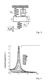
- FIG. 7 shows an example of a typical frequency response of the built-up resonance, the test stand resonance and the axle resonance (from left to the right).
- the amplitude of the built-up resonance has a maximum value between 1 and 2 Hz and the axis resonance has a maximum between 12 and 20 Hz on. Because of these characteristic values for the resonance points of vehicles, it is appropriate to the test bench be interpreted that the test bench resonance between the maximum the build-up resonance and the axis resonance is (typically at approx. 7 Hz).
- Vibration dampers In principle, all known methods for the evaluation of Vibration dampers have the disadvantage that they are actually one by one Arousal enforced and muffled by the vehicle damper Oscillation of a vibrating system consisting of a contact plate and look at and evaluate the vehicle wheel with suspension. With In other words, assuming a fixed vehicle body, determines the damping with which the vehicle damper damped the tester's oscillator (i.e., the footprint). One However, such determined damping amount is not a judgment the actually interesting damping suitable, with which the Shock absorber dampens the vehicle body.
- the attenuation measure determined according to the invention is characterized the decay behavior or resonance overshoot of a damped by the vibration damper vibration of the vehicle body (in contrast to the damping of a forced Vibration of footprint plate and vehicle wheel as in the state of Technology).
- a preferred attenuation measure for characterizing the Decay behavior is Lehr's damping measure.
- the Calculation of the Lehrschen attenuation measure on the basis of a proportionate Vehicle mass with which the vibration damper is loaded be executed.
- this proportionate Vehicle mass corresponding to the vehicle weight that is supported on the respective vehicle, about a quarter of the total Vehicle mass.
- the permissible axle load e.g. from the vehicle license, is known.
- this can be corrected with a factor (for example 0.9).
- the Use of the permissible axle load has the advantage that the vehicle is considered under the condition of maximum loading and the vibration behavior can be taken into account for this case.
- the damping amount can be determined by determining the actual proportionate vehicle mass m 4 for the vibration damper to be tested on the basis of a measurement.
- the proportionate vehicle mass m 4 is particularly suitable for a scale on which the respective vehicle wheel to be tested is placed. It is expedient to take into account the unsprung masses m 2 of the wheel and the suspension, since the measured weight of the total mass m 4 + m 2 corresponds. For simplicity, it can be assumed here that m 2 is about 10% of m 4 . In this case, the measured value for the total mass acting on the footplate can be corrected by a factor of, for example, 0.9 in order to obtain a sufficiently accurate estimate for the proportionate vehicle mass m 4 .
- a particularly preferred embodiment of the invention provides that the balance is integrated into the test device.
- the step for determining the proportionate vehicle mass for example, on the measurement of a lowering of the footprint plate by the load with the vehicle can be done. Due to the known spring constants of the support plate supporting spring elements so the proportionate vehicle mass m 4 can be determined without additional design effort.
- the damping measure determined according to the invention is largely independent of the properties of the test apparatus used and correctly characterizes the damping properties for vehicle vibrations, it can be used for the reliable and reproducible assessment of vibration dampers.
- the damping measure according to the invention makes it possible to reliably test the functionality of shock absorbers, as is desirable, for example, for a main vehicle inspection. Based on an empirical study with different vehicles, it was found that functioning shock absorbers usually have a Lehr's damping ratio of ⁇ > 0.2.
- the inventive method has another Judgment step for judging the damping properties of the Vibration damper, which is for the vibration damper to be tested determined attenuation ⁇ with a predetermined Limit G is compared.
- a predetermined Limit G a predetermined Limit G.
- This compensation step is especially for vehicles with low Attenuation constant, such as smaller vehicles with low Vehicle weight, an advantage, since in this case the relative measurement error by the friction damping in the test bench in the determination of the Damping constant of the vibration is important.
- the damping constant K P of the test device can be determined, for example, by detecting the vibration amplitudes of the unloaded contact plate after completion of the excitation in a swing-out test. Since the damping constant K P of the test device is largely constant, it can be determined and stored once before the actual test of the shock absorber. To improve the accuracy and a parameter field for the damping constant K P , for example, depending on the load acting on the support plate or the vibration amplitude, determined and used for compensation. The evaluation of the decay test can be done, for example, with the help of the logarithmic decrement. In this way, the decay constant of the oscillation or the damping constant K P of the test stand can be determined directly on the basis of amplitude ratios in the swing-out test.
- An apparatus for determining a damping measure for vibrations Vehicles may use excitation means to excite one a vehicle connected to a vibration damper, detection means for detecting the movement of the excited vehicle wheel, first Calculating means for determining a damping constant K of Vibration damper based on the detected movement of the vehicle wheel and second calculating means for determining an attenuation amount for the damping of a vehicle vibration by the Have vibration.
- the device comprises a footprint plate on which the Vehicle wheel gets up.
- the uprising plate can have an elastic Element to be connected to a drive unit, which the uprising plate periodically excited. Due to the excitement leads the riot plate a vertical vibration, which on the upstanding Vehicle wheel is transmitted.
- Detecting means may be an amplitude of the movement of the footprint plate to capture. This is preferably done by that on the footprint plate corresponding sensors for determining the position or Height of the riot plate are attached. Alternatively, the detection means also directly detect the movement of the excited vehicle wheel. For this purpose, appropriate sensors on the wheel or the suspension be attached to the vehicle.
- the calculation means determine the damping constant K of Vibration damper preferably based on the ratio A between an excitation amplitude r of the drive unit and the detected Amplitude of movement of the vehicle wheel or the footprint plate in the case of resonance. Based on the measured amplitude of the movement of the Spring-mass system consisting of a contact plate and vehicle wheel in case of resonance can the properties of the moving spring-mass system, how the damping by the vibration damper, be determined. By means of the known from the vibrational theory relationships Thus, the damping constant K of the vibration damper determined become.
- the calculation means determine the damping constant K taking into account the mass m 1 of the contact plate and the spring constant D 1 of the elastic element.
- the damping constant K for the respective vibration damper of the vehicle can be determined largely independently of the properties of the test apparatus.
- the judging means preferably determines the Lehr's attenuation for a vibration of the vehicle body based on the determined Damping constant K of the vibration damper.
- the device has vehicle mass determining means for determining the proportionate vehicle mass m 4 .
- the footprint of the test device may be supported via another elastic element, a so-called emphasizeddlingfeder, to carry a greater proportion of the vehicle mass and relieve the drive of the excitation means.
- the provision of the further elastic element also has the advantage that the contact plate does not drop so much when driving on the vehicle. This effect can also be used to determine the pro rata vehicle mass m 4 , in that the detection means detect the lowering of the contact plate due to the load on the proportionate vehicle mass m 4 .
- the proportionate vehicle mass m 4 can be determined exactly for each vehicle wheel, without an additional weighing device is necessary.
- the vehicle mass determination means determine the proportionate vehicle mass m 4 preferably taking into account the spring constant D 5 of the further elastic element and the spring constant D 1 of the elastic element.
- D D 1 + D 5 .
- Assessment means can determine the damping properties of the vibration damper by the determined damping amount is compared with a predetermined limit value G.
- the calculation means may comprise a compensation device which subtracts from the determined value for the damping constant K the damping constant K P of the test apparatus so as to obtain a corrected damping constant K 'of the vibration damper.
- Fig. 2 shows a vibration model for a vehicle on a shock absorber tester with four masses m 1 to m 4 , where m 1 is the mass of the stand plate of the test stand, m 2 unsprung masses of a vehicle wheel (wheel mass, axle mass, mass of the suspension, etc. ), m 3 is the mass of the shock absorber and m 4 is the proportionate body mass of the vehicle.
- the respective deflections of the masses in their vibrations are denoted by x 0 to x 4 , where x 0 represents the deflection of the excitation, for example by a crank mechanism.
- the elastic elements shown as springs are the test bench spring between crank mechanism and test stand plate, the tire spring, the vehicle spring and the spring effect of the shock absorber eye.
- the corresponding spring constants are denoted by D 1 to D 4 in this order.
- the damping constant of the vibration damper of the vehicle is denoted by K.
- the attenuation constant K will first be determined in the following.
- the power P (t) can then be determined. Integrating over a period of oscillation, the active power of the test bench determined. Here is the amplitude of the swinging motion of the footplate and f the excitation frequency. With ⁇ 0 , the phase angle between the excitation vibration and the vibration of the contact plate is called.
- the power consumed by the shock absorber may increase be calculated. Again, integration over a period of oscillation determines the effective power of the shock absorber:
- the determined value for the damping constant K applies to the conditions (speed v D , excitation amplitude r) under which the measurement was taken.
- the damping constant K for a shock absorber can be determined with sufficient accuracy.
- the damping constant K can be determined on the basis of the ascertained amplitude ratio A, the spring constant D 1 of the test bench spring and the plate mass m 1 of the test stand.
- the resonance overshoot is forced Vibration of the test bench used to attenuate this Vibration through the vibration damper of the vehicle or determine its damping constant K.
- the technique in which the attenuation measure as a criterion for assessment the vibration damper is used this is in the present Invention only an intermediate step or an intermediate size represents.
- the vehicle is now considered without a test bench and determined on the basis of the vehicle characteristics the Lehr'sche damping measure for the damping of vibration of the vehicle body by the vibration damper as a judgment measure.
- a vibration of the vehicle body with a proportionate vehicle mass m 4 and the vehicle spring D 3 is considered. This is attenuated by the vibration damper with the damper constant K determined by the above method.
- ⁇ A of the body structure between different vehicles usually has no great differences, for this purpose, a predetermined known value can be assumed. This can be specified eg for different vehicle categories.
- Typical superstructure resonance frequencies for cars are 1.4 Hz, for off-road vehicles (SUVs) 1.6 Hz and for transporters 1.8 Hz.
- FIG. 9 shows a flow chart for a method for determining a damping measure for vibration damper according to an embodiment of the present invention.
- step 100 the proportionate vehicle mass m 4 , with which the vibration damper to be tested is loaded, determined. This can be done by detecting the lowering of the contact plate by the load with the vehicle weight when the exciter drive is at rest after the vehicle has hit the upright plate.
- the test stand is used as a balance and the proportionate vehicle mass m 4 determined on the basis of the spring set on the corresponding proportionate vehicle weight
- D the effective spring constant of the test bench and g is the gravitational acceleration.
- D D 1 + D 5 .
- the step for detecting the proportionate vehicle mass m 4 may also take place following the detection of the movement of the excited vehicle wheel or the determination of the damping constant K of the vibration damper.
- the vehicle wheel resting on the footboard would first be forced to vibrate forcibly, and then the weighing operation would take place.
- step 110 the wheel standing up on the footing plate becomes a forced vibration.
- This is the uprising plate via an elastic element from a drive unit to vertical Vibrations excited, wherein the excitation frequency is varied.
- the speed the drive unit slowly increased to pass through the resonance point.
- the excitation also with a higher speed begin, which is then slowly lowered, as long as one Resonance occurs.
- step 120 the movement of the energized vehicle wheel or the footprint plate is detected.
- a marking may be provided on the vehicle wheel, which is detected by corresponding sensors.
- step 130 the damping constant K of the vibration damper is determined on the basis of the detected movement of the vehicle wheel based on the relationship indicated in formula 2. As already explained, this calculation is based on the evaluation of the ratio between the excitation amplitude r and the detected amplitude the movement of the contact plate or the vehicle wheel in resonance.
- the determined value for the damping constant K is corrected in step 140.
- This compensation step is useful mainly for smaller or lighter vehicles with smaller damping constants, since for these vehicles, the test bench damping can be up to 15% of the total vibration damping.
- a swing-out test can be carried out be carried out with an unloaded test bench. For this becomes the footprint of the drive unit to a vibration stimulated, and after switching off the drive unit, the amplitude characteristic the damped vibration detected.
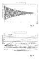
- Fig. 5 shows a typical course of the vibration of the uprising plate in a swing-out attempt.
- the evaluation of the Ausschwings sheds preferably takes place with the help of the logarithmic decrement.
- the damping constant K P of the test bench is generally dependent on the particular disk amplitude (see FIG. 8), it is expedient to perform a swing-out test with the corresponding disk amplitude to be expected during operation of the test bench. It is also possible to determine beforehand the respective damping costs K P for different plate amplitudes and / or vehicle weights and to use the corresponding test bench damping constant K P for the measurement condition (eg plate amplitude) in the correction of the vibration damper constant. In any case, the damping food Ante or the damping constants K P can be determined in advance of the test rig set up and calibration of the dynamometer and stored (eg in a parameter field) will be and are already present in the implementation of the test method for vibration damper.
- step 150 the Lehr'sche damping measure for the vibration of the vehicle body based on the corrected damping constant K ' is determined based on the formula. For this purpose, it is generally sufficient to assume a fixed resonance frequency ⁇ A for the vibration of the vehicle body. Furthermore, the proportional vehicle mass m 4 determined in this example in step 100 is included in the calculation. The determined damping measure ⁇ can be used as a criterion for assessing the resonance peaking or damping of the vibration of the vehicle body.
- step 160 the determined attenuation amount ⁇ is given with a predetermined one Threshold G, for example 0.1, compared. investigations have shown that the shock absorbers of new vehicles as well functioning shock absorbers of older vehicles usually this Exceed limit.
- step 160 If the test in step 160 shows that the Lehr's damping measure the vibration damper exceeds the preset limit G, so the vibration damper in step 180 is functioning explained.
- step 170 a defective vibration damper explained, where appropriate appropriate action can be taken.
- the explained method for determining a damping measure for Vibration of vehicles is thus used for testing built-in Shock absorbers of motor vehicles and can be used for example in the Be used for a main vehicle inspection.
- the great Advantage over known methods is that a meaningful, reliable assessment of functionality can be determined by shock absorbers, which is independent of vehicle type and the characteristics of the test bench used provides a reliable assessment measure.
- Fig. 1 shows schematically an embodiment of a shock absorber test according to the present invention.
- a vibration damper 1 a vehicle 2, a vehicle spring 12, a suspension 13 and a body of the vehicle 14 are shown schematically.
- the attenuation constant K, of the vehicle spring 12 corresponds to the damper 1
- the spring constant D 3 of the wheel suspension 13 the unsprung wheel mass m 2 and the body 14 shown symbolically the proportional body mass m 4.
- the shock absorber test stand has a contact plate 7, a frame 8, a double rocker 9, a drive unit 4 and a first elastic Element 3 on.
- the contact plate 7 is on the double rocker 9 and the first elastic element 3 with the drive unit 4 connected, which acts as a crank mechanism and the contact plate 7 and the vehicle wheel 2 is vibrated.
- a control unit 15 controls the speed of the drive unit 4 such that the oscillating System resonates.
- Another elastic element 6 supports the footprint 7 and carries a large part of the vehicle weight (typically between 60 and 90%), in order to decrease too much To avoid contact plate 7 when loaded with the vehicle.
- detection means 5 In the vicinity of the support plate 7 detection means 5 are provided, which detect the movement of the contact plate 7 and a corresponding Signal X to calculating means 10, 11, vehicle mass determining means 16 and the control unit 15 deliver. In the control unit 15 This signal X can be used to determine that the right speed for resonance of the oscillating system achieved is.
- Vehicle mass determining means 16 determine when the excitation is switched off on the basis of the reduction s of the contact plate 7 when the vehicle is approaching and the effective spring constant D is the proportionate vehicle mass m 4 .
- the second calculating means 11 determines the Lehr's damping amount ⁇ for vibration of the vehicle body based on the proportionate vehicle mass m 4 and the damping constant K of the vibration damper 1 (Formula 3).
- the assessment means 17 Based on a comparison of the determined attenuation ⁇ with a given limit value G is the assessment means 17 the Functionality of the vibration damper 1 judged and a corresponding binary test signal generated, which indicates with "0" that the vibration damper 1 does not meet the test criterion, and with "1" indicates that the test vibration damper 1 passed the test Has.
Landscapes
- Physics & Mathematics (AREA)
- General Physics & Mathematics (AREA)
- Measurement Of Mechanical Vibrations Or Ultrasonic Waves (AREA)
- Vibration Prevention Devices (AREA)
- Vehicle Body Suspensions (AREA)
- Automobile Manufacture Line, Endless Track Vehicle, Trailer (AREA)
Priority Applications (1)
| Application Number | Priority Date | Filing Date | Title |
|---|---|---|---|
| PL05002972T PL1564538T3 (pl) | 2004-02-12 | 2005-02-11 | Sposób i urządzenie do wyznaczania miary tłumienia drgań pojazdów |
Applications Claiming Priority (2)
| Application Number | Priority Date | Filing Date | Title |
|---|---|---|---|
| DE102004006986 | 2004-02-12 | ||
| DE102004006986A DE102004006986A1 (de) | 2004-02-12 | 2004-02-12 | Verfahren und Vorrichtung zum Bestimmen eines Dämpfungsmaßes für Schwingungen von Fahrzeugen |
Publications (3)
| Publication Number | Publication Date |
|---|---|
| EP1564538A2 true EP1564538A2 (fr) | 2005-08-17 |
| EP1564538A3 EP1564538A3 (fr) | 2006-06-07 |
| EP1564538B1 EP1564538B1 (fr) | 2010-06-09 |
Family
ID=34684028
Family Applications (1)
| Application Number | Title | Priority Date | Filing Date |
|---|---|---|---|
| EP05002972A Expired - Lifetime EP1564538B1 (fr) | 2004-02-12 | 2005-02-11 | Procédé et dispositif de détermination d'une mesure de l'amortissement des vibrations de véhicules |
Country Status (7)
| Country | Link |
|---|---|
| EP (1) | EP1564538B1 (fr) |
| AT (1) | ATE470846T1 (fr) |
| DE (2) | DE102004006986A1 (fr) |
| DK (1) | DK1564538T3 (fr) |
| ES (1) | ES2346227T3 (fr) |
| PL (1) | PL1564538T3 (fr) |
| PT (1) | PT1564538E (fr) |
Cited By (1)
| Publication number | Priority date | Publication date | Assignee | Title |
|---|---|---|---|---|
| CN116465653A (zh) * | 2023-04-24 | 2023-07-21 | 东风柳州汽车有限公司 | 一种减振系统的固有频率测试装置及其测试方法 |
Family Cites Families (2)
| Publication number | Priority date | Publication date | Assignee | Title |
|---|---|---|---|---|
| DE4439997C1 (de) * | 1994-11-09 | 1996-06-05 | Fichtel & Sachs Ag | Verfahren und Vorrichtung zum Bestimmen der Dämpfungsgüte eines Schwingungsdämpfers |
| DE10143492A1 (de) * | 2001-09-05 | 2003-03-20 | Maha Gmbh & Co Kg | Verfahren und Vorrichtung zum Prüfen von Fahrzeugschwingungsdämpfern und zum Lokalisieren von Karosseriegeräuschen |
-
2004
- 2004-02-12 DE DE102004006986A patent/DE102004006986A1/de not_active Withdrawn
-
2005
- 2005-02-11 PT PT05002972T patent/PT1564538E/pt unknown
- 2005-02-11 EP EP05002972A patent/EP1564538B1/fr not_active Expired - Lifetime
- 2005-02-11 PL PL05002972T patent/PL1564538T3/pl unknown
- 2005-02-11 ES ES05002972T patent/ES2346227T3/es not_active Expired - Lifetime
- 2005-02-11 DE DE502005009703T patent/DE502005009703D1/de not_active Expired - Lifetime
- 2005-02-11 DK DK05002972.7T patent/DK1564538T3/da active
- 2005-02-11 AT AT05002972T patent/ATE470846T1/de active
Cited By (1)
| Publication number | Priority date | Publication date | Assignee | Title |
|---|---|---|---|---|
| CN116465653A (zh) * | 2023-04-24 | 2023-07-21 | 东风柳州汽车有限公司 | 一种减振系统的固有频率测试装置及其测试方法 |
Also Published As
| Publication number | Publication date |
|---|---|
| ES2346227T3 (es) | 2010-10-13 |
| DK1564538T3 (da) | 2010-09-27 |
| ATE470846T1 (de) | 2010-06-15 |
| EP1564538A3 (fr) | 2006-06-07 |
| EP1564538B1 (fr) | 2010-06-09 |
| DE102004006986A1 (de) | 2005-09-01 |
| PL1564538T3 (pl) | 2010-11-30 |
| PT1564538E (pt) | 2010-08-17 |
| DE502005009703D1 (de) | 2010-07-22 |
Similar Documents
| Publication | Publication Date | Title |
|---|---|---|
| EP0756701B1 (fr) | Procede pour la determination des caracteristiques des amortisseurs montes sur un vehicule | |
| EP2136195A2 (fr) | Procédé et dispositif d'essai d'un amortisseur de chocs intégré dans un véhicule automobile | |
| EP0611960B1 (fr) | Méthod pour examiner un amortisseur de vibration d'un véhicule | |
| EP2159561B1 (fr) | Procédé et dispositif d'essai d'un amortisseur d'oscillations d'un véhicule automobile en état intégré | |
| DE102008041745B4 (de) | Verfahren und Vorrichtung zum Prüfen wenigstens eines Schwingungsdämpfers eines Kraftfahrzeugs im eingebauten Zustand | |
| EP1657471A2 (fr) | Méthode pour amortir les vibrations dans un sytème de suspension ainsi que suspension correspondante | |
| EP0779972B1 (fr) | ContrÔle d'une caractéristique d'un amortisseur sur un véhicule | |
| EP1291635B1 (fr) | Procédé et dispositif d'essai d'amortisseurs de véhicule | |
| EP0921387A2 (fr) | Méthode et dispositif pour tester des amortisseurs montés | |
| DE4439997C1 (de) | Verfahren und Vorrichtung zum Bestimmen der Dämpfungsgüte eines Schwingungsdämpfers | |
| EP1564538B1 (fr) | Procédé et dispositif de détermination d'une mesure de l'amortissement des vibrations de véhicules | |
| EP2520921A2 (fr) | Procédé de diagnostic d'un état de fonctionnement d'un composant d'un châssis actif de véhicule automobile | |
| DE10337212B4 (de) | System und Verfahren zur Ermittlung eines Beladungszustandes eines Fahrzeugs oder eines Anhängers | |
| DE102009014749B4 (de) | Verfahren zum Betreiben eines Dämpfers in einem Kraftfahrzeug | |
| EP1080357B1 (fr) | Dispositif pour tester des suspensions de roue | |
| DE10017558A1 (de) | Gerät zur Überprüfung der Wirksamkeit von Schwingungsdämpern | |
| EP1557656B1 (fr) | Procédé et dispositif de détermination de l'amortissement de la suspension d'un véhicule | |
| EP0986743A1 (fr) | Procede pour tester des amortisseurs montes | |
| DE102011087594A1 (de) | Verfahren zur Funktionsüberwachung von Rad-Schwingungsdämpfern | |
| DE3826196C2 (fr) | ||
| DE2362661A1 (de) | Verfahren zur pruefung der funktionsfaehigkeit von stossdaempfern | |
| DE19823369A1 (de) | Verfahren zum Prüfen einer Radaufhängung | |
| DE102004024239A1 (de) | Mess- und Auswerteverfahren zum Prüfen von Schwingungsdämpfern | |
| EP4450948A1 (fr) | Procédé et dispositif de détermination de la stabilité de conduite d'un deux roues | |
| EP4467941A1 (fr) | Évaluation très précise de signaux dépendants du chemin |
Legal Events
| Date | Code | Title | Description |
|---|---|---|---|
| PUAI | Public reference made under article 153(3) epc to a published international application that has entered the european phase |
Free format text: ORIGINAL CODE: 0009012 |
|
| AK | Designated contracting states |
Kind code of ref document: A2 Designated state(s): AT BE BG CH CY CZ DE DK EE ES FI FR GB GR HU IE IS IT LI LT LU MC NL PL PT RO SE SI SK TR |
|
| AX | Request for extension of the european patent |
Extension state: AL BA HR LV MK YU |
|
| PUAL | Search report despatched |
Free format text: ORIGINAL CODE: 0009013 |
|
| AK | Designated contracting states |
Kind code of ref document: A3 Designated state(s): AT BE BG CH CY CZ DE DK EE ES FI FR GB GR HU IE IS IT LI LT LU MC NL PL PT RO SE SI SK TR |
|
| AX | Request for extension of the european patent |
Extension state: AL BA HR LV MK YU |
|
| 17P | Request for examination filed |
Effective date: 20061207 |
|
| AKX | Designation fees paid |
Designated state(s): AT BE BG CH CY CZ DE DK EE ES FI FR GB GR HU IE IS IT LI LT LU MC NL PL PT RO SE SI SK TR |
|
| 17Q | First examination report despatched |
Effective date: 20070810 |
|
| GRAP | Despatch of communication of intention to grant a patent |
Free format text: ORIGINAL CODE: EPIDOSNIGR1 |
|
| GRAS | Grant fee paid |
Free format text: ORIGINAL CODE: EPIDOSNIGR3 |
|
| GRAA | (expected) grant |
Free format text: ORIGINAL CODE: 0009210 |
|
| AK | Designated contracting states |
Kind code of ref document: B1 Designated state(s): AT BE BG CH CY CZ DE DK EE ES FI FR GB GR HU IE IS IT LI LT LU MC NL PL PT RO SE SI SK TR |
|
| REG | Reference to a national code |
Ref country code: CH Ref legal event code: EP |
|
| REG | Reference to a national code |
Ref country code: IE Ref legal event code: FG4D Free format text: LANGUAGE OF EP DOCUMENT: GERMAN |
|
| REF | Corresponds to: |
Ref document number: 502005009703 Country of ref document: DE Date of ref document: 20100722 Kind code of ref document: P |
|
| REG | Reference to a national code |
Ref country code: PT Ref legal event code: SC4A Free format text: AVAILABILITY OF NATIONAL TRANSLATION Effective date: 20100809 |
|
| REG | Reference to a national code |
Ref country code: CH Ref legal event code: NV Representative=s name: MICHELI & CIE SA |
|
| REG | Reference to a national code |
Ref country code: NL Ref legal event code: T3 |
|
| REG | Reference to a national code |
Ref country code: GR Ref legal event code: EP Ref document number: 20100402001 Country of ref document: GR |
|
| REG | Reference to a national code |
Ref country code: DK Ref legal event code: T3 |
|
| REG | Reference to a national code |
Ref country code: ES Ref legal event code: FG2A Ref document number: 2346227 Country of ref document: ES Kind code of ref document: T3 |
|
| REG | Reference to a national code |
Ref country code: RO Ref legal event code: EPE |
|
| PG25 | Lapsed in a contracting state [announced via postgrant information from national office to epo] |
Ref country code: LT Free format text: LAPSE BECAUSE OF FAILURE TO SUBMIT A TRANSLATION OF THE DESCRIPTION OR TO PAY THE FEE WITHIN THE PRESCRIBED TIME-LIMIT Effective date: 20100609 Ref country code: SE Free format text: LAPSE BECAUSE OF FAILURE TO SUBMIT A TRANSLATION OF THE DESCRIPTION OR TO PAY THE FEE WITHIN THE PRESCRIBED TIME-LIMIT Effective date: 20100609 |
|
| LTIE | Lt: invalidation of european patent or patent extension |
Effective date: 20100609 |
|
| PG25 | Lapsed in a contracting state [announced via postgrant information from national office to epo] |
Ref country code: SI Free format text: LAPSE BECAUSE OF FAILURE TO SUBMIT A TRANSLATION OF THE DESCRIPTION OR TO PAY THE FEE WITHIN THE PRESCRIBED TIME-LIMIT Effective date: 20100609 |
|
| REG | Reference to a national code |
Ref country code: PL Ref legal event code: T3 |
|
| PG25 | Lapsed in a contracting state [announced via postgrant information from national office to epo] |
Ref country code: CY Free format text: LAPSE BECAUSE OF FAILURE TO SUBMIT A TRANSLATION OF THE DESCRIPTION OR TO PAY THE FEE WITHIN THE PRESCRIBED TIME-LIMIT Effective date: 20100609 |
|
| PG25 | Lapsed in a contracting state [announced via postgrant information from national office to epo] |
Ref country code: EE Free format text: LAPSE BECAUSE OF FAILURE TO SUBMIT A TRANSLATION OF THE DESCRIPTION OR TO PAY THE FEE WITHIN THE PRESCRIBED TIME-LIMIT Effective date: 20100609 |
|
| PG25 | Lapsed in a contracting state [announced via postgrant information from national office to epo] |
Ref country code: SK Free format text: LAPSE BECAUSE OF FAILURE TO SUBMIT A TRANSLATION OF THE DESCRIPTION OR TO PAY THE FEE WITHIN THE PRESCRIBED TIME-LIMIT Effective date: 20100609 Ref country code: IS Free format text: LAPSE BECAUSE OF FAILURE TO SUBMIT A TRANSLATION OF THE DESCRIPTION OR TO PAY THE FEE WITHIN THE PRESCRIBED TIME-LIMIT Effective date: 20101009 |
|
| PLBE | No opposition filed within time limit |
Free format text: ORIGINAL CODE: 0009261 |
|
| STAA | Information on the status of an ep patent application or granted ep patent |
Free format text: STATUS: NO OPPOSITION FILED WITHIN TIME LIMIT |
|
| PGFP | Annual fee paid to national office [announced via postgrant information from national office to epo] |
Ref country code: IE Payment date: 20110216 Year of fee payment: 7 Ref country code: DK Payment date: 20110222 Year of fee payment: 7 |
|
| 26N | No opposition filed |
Effective date: 20110310 |
|
| PGFP | Annual fee paid to national office [announced via postgrant information from national office to epo] |
Ref country code: FI Payment date: 20110217 Year of fee payment: 7 Ref country code: NL Payment date: 20110225 Year of fee payment: 7 Ref country code: CH Payment date: 20110222 Year of fee payment: 7 Ref country code: CZ Payment date: 20110203 Year of fee payment: 7 Ref country code: AT Payment date: 20110217 Year of fee payment: 7 Ref country code: PT Payment date: 20110201 Year of fee payment: 7 Ref country code: TR Payment date: 20110208 Year of fee payment: 7 Ref country code: PL Payment date: 20110201 Year of fee payment: 7 Ref country code: RO Payment date: 20110207 Year of fee payment: 7 |
|
| PGRI | Patent reinstated in contracting state [announced from national office to epo] |
Ref country code: IT Effective date: 20110501 |
|
| PGFP | Annual fee paid to national office [announced via postgrant information from national office to epo] |
Ref country code: GR Payment date: 20110225 Year of fee payment: 7 |
|
| REG | Reference to a national code |
Ref country code: DE Ref legal event code: R097 Ref document number: 502005009703 Country of ref document: DE Effective date: 20110309 |
|
| PGFP | Annual fee paid to national office [announced via postgrant information from national office to epo] |
Ref country code: GB Payment date: 20110221 Year of fee payment: 7 Ref country code: BE Payment date: 20110221 Year of fee payment: 7 |
|
| PG25 | Lapsed in a contracting state [announced via postgrant information from national office to epo] |
Ref country code: MC Free format text: LAPSE BECAUSE OF NON-PAYMENT OF DUE FEES Effective date: 20110228 |
|
| REG | Reference to a national code |
Ref country code: PT Ref legal event code: MM4A Free format text: LAPSE DUE TO NON-PAYMENT OF FEES Effective date: 20120813 |
|
| BERE | Be: lapsed |
Owner name: MAHA MASCHINENBAU HALDENWANG G.M.B.H. & CO. KG Effective date: 20120228 |
|
| REG | Reference to a national code |
Ref country code: NL Ref legal event code: V1 Effective date: 20120901 |
|
| REG | Reference to a national code |
Ref country code: CH Ref legal event code: PL |
|
| GBPC | Gb: european patent ceased through non-payment of renewal fee |
Effective date: 20120211 |
|
| REG | Reference to a national code |
Ref country code: GR Ref legal event code: ML Ref document number: 20100402001 Country of ref document: GR Effective date: 20120905 |
|
| PG25 | Lapsed in a contracting state [announced via postgrant information from national office to epo] |
Ref country code: FI Free format text: LAPSE BECAUSE OF NON-PAYMENT OF DUE FEES Effective date: 20120211 Ref country code: CZ Free format text: LAPSE BECAUSE OF NON-PAYMENT OF DUE FEES Effective date: 20120211 Ref country code: CH Free format text: LAPSE BECAUSE OF NON-PAYMENT OF DUE FEES Effective date: 20120229 Ref country code: LI Free format text: LAPSE BECAUSE OF NON-PAYMENT OF DUE FEES Effective date: 20120229 |
|
| REG | Reference to a national code |
Ref country code: DK Ref legal event code: EBP |
|
| REG | Reference to a national code |
Ref country code: IE Ref legal event code: MM4A |
|
| PG25 | Lapsed in a contracting state [announced via postgrant information from national office to epo] |
Ref country code: GR Free format text: LAPSE BECAUSE OF NON-PAYMENT OF DUE FEES Effective date: 20120905 Ref country code: PT Free format text: LAPSE BECAUSE OF NON-PAYMENT OF DUE FEES Effective date: 20120813 |
|
| REG | Reference to a national code |
Ref country code: AT Ref legal event code: MM01 Ref document number: 470846 Country of ref document: AT Kind code of ref document: T Effective date: 20120211 |
|
| PG25 | Lapsed in a contracting state [announced via postgrant information from national office to epo] |
Ref country code: BE Free format text: LAPSE BECAUSE OF NON-PAYMENT OF DUE FEES Effective date: 20120228 |
|
| PG25 | Lapsed in a contracting state [announced via postgrant information from national office to epo] |
Ref country code: AT Free format text: LAPSE BECAUSE OF NON-PAYMENT OF DUE FEES Effective date: 20120211 Ref country code: GB Free format text: LAPSE BECAUSE OF NON-PAYMENT OF DUE FEES Effective date: 20120211 Ref country code: NL Free format text: LAPSE BECAUSE OF NON-PAYMENT OF DUE FEES Effective date: 20120901 Ref country code: IE Free format text: LAPSE BECAUSE OF NON-PAYMENT OF DUE FEES Effective date: 20120211 |
|
| PG25 | Lapsed in a contracting state [announced via postgrant information from national office to epo] |
Ref country code: RO Free format text: LAPSE BECAUSE OF NON-PAYMENT OF DUE FEES Effective date: 20120211 |
|
| PG25 | Lapsed in a contracting state [announced via postgrant information from national office to epo] |
Ref country code: LU Free format text: LAPSE BECAUSE OF NON-PAYMENT OF DUE FEES Effective date: 20110211 Ref country code: PL Free format text: LAPSE BECAUSE OF NON-PAYMENT OF DUE FEES Effective date: 20120211 |
|
| REG | Reference to a national code |
Ref country code: PL Ref legal event code: LAPE |
|
| PG25 | Lapsed in a contracting state [announced via postgrant information from national office to epo] |
Ref country code: BG Free format text: LAPSE BECAUSE OF FAILURE TO SUBMIT A TRANSLATION OF THE DESCRIPTION OR TO PAY THE FEE WITHIN THE PRESCRIBED TIME-LIMIT Effective date: 20100909 |
|
| PG25 | Lapsed in a contracting state [announced via postgrant information from national office to epo] |
Ref country code: DK Free format text: LAPSE BECAUSE OF NON-PAYMENT OF DUE FEES Effective date: 20120229 Ref country code: HU Free format text: LAPSE BECAUSE OF FAILURE TO SUBMIT A TRANSLATION OF THE DESCRIPTION OR TO PAY THE FEE WITHIN THE PRESCRIBED TIME-LIMIT Effective date: 20100609 |
|
| PG25 | Lapsed in a contracting state [announced via postgrant information from national office to epo] |
Ref country code: TR Free format text: LAPSE BECAUSE OF NON-PAYMENT OF DUE FEES Effective date: 20120211 |
|
| REG | Reference to a national code |
Ref country code: FR Ref legal event code: PLFP Year of fee payment: 12 |
|
| REG | Reference to a national code |
Ref country code: FR Ref legal event code: PLFP Year of fee payment: 13 |
|
| REG | Reference to a national code |
Ref country code: FR Ref legal event code: PLFP Year of fee payment: 14 |
|
| PGFP | Annual fee paid to national office [announced via postgrant information from national office to epo] |
Ref country code: FR Payment date: 20230220 Year of fee payment: 19 Ref country code: ES Payment date: 20230317 Year of fee payment: 19 |
|
| PGFP | Annual fee paid to national office [announced via postgrant information from national office to epo] |
Ref country code: IT Payment date: 20230228 Year of fee payment: 19 Ref country code: DE Payment date: 20230228 Year of fee payment: 19 |
|
| REG | Reference to a national code |
Ref country code: DE Ref legal event code: R119 Ref document number: 502005009703 Country of ref document: DE |
|
| PG25 | Lapsed in a contracting state [announced via postgrant information from national office to epo] |
Ref country code: DE Free format text: LAPSE BECAUSE OF NON-PAYMENT OF DUE FEES Effective date: 20240903 |
|
| PG25 | Lapsed in a contracting state [announced via postgrant information from national office to epo] |
Ref country code: FR Free format text: LAPSE BECAUSE OF NON-PAYMENT OF DUE FEES Effective date: 20240229 |
|
| PG25 | Lapsed in a contracting state [announced via postgrant information from national office to epo] |
Ref country code: FR Free format text: LAPSE BECAUSE OF NON-PAYMENT OF DUE FEES Effective date: 20240229 Ref country code: DE Free format text: LAPSE BECAUSE OF NON-PAYMENT OF DUE FEES Effective date: 20240903 |
|
| PG25 | Lapsed in a contracting state [announced via postgrant information from national office to epo] |
Ref country code: IT Free format text: LAPSE BECAUSE OF NON-PAYMENT OF DUE FEES Effective date: 20240211 |
|
| REG | Reference to a national code |
Ref country code: ES Ref legal event code: FD2A Effective date: 20250331 |
|
| PG25 | Lapsed in a contracting state [announced via postgrant information from national office to epo] |
Ref country code: ES Free format text: LAPSE BECAUSE OF NON-PAYMENT OF DUE FEES Effective date: 20240212 |