EP1564543A2 - Messkammer für einen photoakustischen Gassensor - Google Patents
Messkammer für einen photoakustischen Gassensor Download PDFInfo
- Publication number
- EP1564543A2 EP1564543A2 EP04450223A EP04450223A EP1564543A2 EP 1564543 A2 EP1564543 A2 EP 1564543A2 EP 04450223 A EP04450223 A EP 04450223A EP 04450223 A EP04450223 A EP 04450223A EP 1564543 A2 EP1564543 A2 EP 1564543A2
- Authority
- EP
- European Patent Office
- Prior art keywords
- pipe section
- outlet
- chamber
- resonant
- measuring
- Prior art date
- Legal status (The legal status is an assumption and is not a legal conclusion. Google has not performed a legal analysis and makes no representation as to the accuracy of the status listed.)
- Granted
Links
Images


Classifications
-
- G—PHYSICS
- G01—MEASURING; TESTING
- G01N—INVESTIGATING OR ANALYSING MATERIALS BY DETERMINING THEIR CHEMICAL OR PHYSICAL PROPERTIES
- G01N29/00—Investigating or analysing materials by the use of ultrasonic, sonic or infrasonic waves; Visualisation of the interior of objects by transmitting ultrasonic or sonic waves through the object
- G01N29/04—Analysing solids
- G01N29/045—Analysing solids by imparting shocks to the workpiece and detecting the vibrations or the acoustic waves caused by the shocks
- G01N29/046—Analysing solids by imparting shocks to the workpiece and detecting the vibrations or the acoustic waves caused by the shocks using the echo of particles imparting on a surface; using acoustic emission of particles
-
- G—PHYSICS
- G01—MEASURING; TESTING
- G01N—INVESTIGATING OR ANALYSING MATERIALS BY DETERMINING THEIR CHEMICAL OR PHYSICAL PROPERTIES
- G01N21/00—Investigating or analysing materials by the use of optical means, i.e. using sub-millimetre waves, infrared, visible or ultraviolet light
- G01N21/17—Systems in which incident light is modified in accordance with the properties of the material investigated
- G01N21/1702—Systems in which incident light is modified in accordance with the properties of the material investigated with opto-acoustic detection, e.g. for gases or analysing solids
-
- G—PHYSICS
- G01—MEASURING; TESTING
- G01N—INVESTIGATING OR ANALYSING MATERIALS BY DETERMINING THEIR CHEMICAL OR PHYSICAL PROPERTIES
- G01N29/00—Investigating or analysing materials by the use of ultrasonic, sonic or infrasonic waves; Visualisation of the interior of objects by transmitting ultrasonic or sonic waves through the object
- G01N29/22—Details, e.g. general constructional or apparatus details
- G01N29/24—Probes
- G01N29/2418—Probes using optoacoustic interaction with the material, e.g. laser radiation, photoacoustics
- G01N29/2425—Probes using optoacoustic interaction with the material, e.g. laser radiation, photoacoustics optoacoustic fluid cells therefor
-
- G—PHYSICS
- G01—MEASURING; TESTING
- G01N—INVESTIGATING OR ANALYSING MATERIALS BY DETERMINING THEIR CHEMICAL OR PHYSICAL PROPERTIES
- G01N2291/00—Indexing codes associated with group G01N29/00
- G01N2291/02—Indexing codes associated with the analysed material
- G01N2291/024—Mixtures
- G01N2291/02408—Solids in gases, e.g. particle suspensions
-
- G—PHYSICS
- G01—MEASURING; TESTING
- G01N—INVESTIGATING OR ANALYSING MATERIALS BY DETERMINING THEIR CHEMICAL OR PHYSICAL PROPERTIES
- G01N2291/00—Indexing codes associated with group G01N29/00
- G01N2291/02—Indexing codes associated with the analysed material
- G01N2291/028—Material parameters
- G01N2291/02809—Concentration of a compound, e.g. measured by a surface mass change
-
- G—PHYSICS
- G01—MEASURING; TESTING
- G01N—INVESTIGATING OR ANALYSING MATERIALS BY DETERMINING THEIR CHEMICAL OR PHYSICAL PROPERTIES
- G01N2291/00—Indexing codes associated with group G01N29/00
- G01N2291/02—Indexing codes associated with the analysed material
- G01N2291/028—Material parameters
- G01N2291/02836—Flow rate, liquid level
-
- G—PHYSICS
- G01—MEASURING; TESTING
- G01N—INVESTIGATING OR ANALYSING MATERIALS BY DETERMINING THEIR CHEMICAL OR PHYSICAL PROPERTIES
- G01N2291/00—Indexing codes associated with group G01N29/00
- G01N2291/02—Indexing codes associated with the analysed material
- G01N2291/028—Material parameters
- G01N2291/02854—Length, thickness
-
- G—PHYSICS
- G01—MEASURING; TESTING
- G01N—INVESTIGATING OR ANALYSING MATERIALS BY DETERMINING THEIR CHEMICAL OR PHYSICAL PROPERTIES
- G01N2291/00—Indexing codes associated with group G01N29/00
- G01N2291/02—Indexing codes associated with the analysed material
- G01N2291/028—Material parameters
- G01N2291/0289—Internal structure, e.g. defects, grain size, texture
Definitions
- the invention relates to a measuring chamber for photoacoustic sensors for continuous measurement of radiation-absorbing substances, in particular of radiation-absorbing particles, in gaseous samples, with at least one inlet and at least one outlet for the samples, one from the sample in the longitudinal direction fürströmbaren pipe section with microphone, and at least one with the Tube section aligned entry and exit point for a laser beam, which inlet and exit point through at least one chamber with respect to the pipe section extended cross-sectional area are spaced from the measuring tube
- Photoacoustics allows a very sensitive measuring technique for the determination of for example trace gas or aerosol concentrations in a carrier gas.
- a solid, liquid or gaseous Sample containing at least one (possibly frequency-selective) radiation-absorbing substance contains, with temporally intermittent electromagnetic radiation, often with visible or infrared light, irradiated. By absorbing the radiation, the substance becomes heated and in the radiation breaks, the heat is released to the environment. This results in a periodic heating and cooling of the irradiated volume, the in turn causes pressure fluctuations of the same period, which propagate as sound waves and can be detected with sensitive microphones.
- the method is schematic shown in Fig. 1.
- resonant cells are used and the period or the frequency of the intermittent irradiation is tuned to the natural frequency of the measuring cell.
- the carrier gas must flow through the cell.
- a simple cell with longitudinal resonance is z. B. Krämer and Niessner in the German utility model no. 200 17 795.8, and Beck, Niessner and Haisch in Anal. Bioanal Chem 375 (2003), p. 1136 f described.
- This cell is shown schematically in FIG. It consists of a tube R whose length determines the resonant frequency and whose diameter is much smaller than the length.
- the extended diameter areas AN at both ends of the resonance tube R are called "notch" filters.
- the change in diameter creates a vibration node of the pressure wave, and may be considered a "free end" (fast-maximum, pressure-node).
- a disadvantage of the measuring cell shown is the susceptibility to contamination given the window through which the intermittent radiation L enters and exits. Especially when using the photoacoustic cell for the measurement of Aerosols, e.g. Soot particles from internal combustion engines or generally in the environment, is this is a serious problem.
- Flow calculations have shown that For example, gas entering the left side of the resonant cell is already in the left "notch" filter Volume vortices that cause a flow to the window, which causes some Deposit particles of the measuring Aerosois there and cause an interfering action. After passage of the sample gas through the resonant cell, it flows directly to the opposite window to, which also some particles of the measuring aerosol are deposited and also cause a disruptive effect.
- the disruptive effect is caused by the deposits on the windows also absorb radiation and generate sound waves that are disturbing over things. Accurate measurement, especially at low concentrations of Measuring aerosols, this is prevented.
- the result of the finite element calculation of Flow in this cell is shown in Fig. 3, with the direction and velocity of the Flow in the figure is characterized by the direction and length of vectors.
- the object of the invention was therefore a measuring cell which, while avoiding the above mentioned disadvantages the contamination of the windows as entry points of the radiation in the Decreased cell and the deposition of the particles of the measuring aerosol slowed down, so that the operation of the measuring cell with high sensitivity over long tent is possible.
- the invention provides that two inlets the opposite ends of the pipe section and at least one outlet a location centrally between the inlets are provided. This will change the flow of Gas in the measuring cell is not led from one side to the other, but it is the gas In split two Tellströme, each on the window side, or left or right of the center or of the resonance tube with the sensor microphone, are fed into the measuring cell. Then the tell streams of the sample gas flow into two Tell cells against each other, and at one or more, the middle or the resonance tube with the sensor microphone nearby Outlet channels again out of the measuring cell. By avoiding the "bouncing" of the Gas flow to the windows or other entry points of the radiation becomes the deposit the particles are considerably reduced at these points.
- the inlets and / or the at least one outlet into annular channels, which coaxially the pipe section surrounded, from which annular channels radial inflow or outflow to the Run pipe section, can be a more even inflow and outflow the measuring cell can be achieved. But this also makes turbulence significant reduces the otherwise deposit of particles at the entry sites of the radiation cause.
- the inlets and / or the pass at least one outlet into annular channels which surround the pipe section coaxially, from which ring channels narrow ring slots extend to the pipe section.
- the second subcell must be resonant or non-resonant become.
- an embodiment of the invention is advantageous in which a Inlet and a central outlet are provided at the ends of a resonant subcell, which extended by a respective chamber with respect to the pipe section Cross-sectional area is limited, with the outlet adjacent chamber a Another pipe section with a similar cross-sectional area as that of the resonant Part cell and a further chamber with respect to the pipe section extended Connect cross-sectional area, and wherein the second inlet at the outlet is provided opposite end of the other pipe section.
- the length of the middle chamber and the further pipe section in each case about half the length of the pipe section of the resonant tell cell amount.
- the length of the middle chamber and the other Tube section each chosen approximately equal to the length of the resonant subcell.
- FIG. 1 shows schematically the principle of photoacoustic measurement
- Fig. 2 shows the basic structure of a (longitudinal) resonant 3 is an illustration of the flow in the measuring cell of FIG Fig. 2
- Fig. 4 shows a first embodiment of the measuring cell according to the invention with not FIG. 5 is a longitudinal section through another one.
- Fig. 6 is an equivalent to Fig. 4 representation of the flow in an inventive Measuring cell.
- the resonant frequency of the laser beam L axially interspersed measuring cell resonance tube R with the microphone M is determined primarily by its length. at Approximately symmetrical reflection conditions at the pipe ends has the standing acoustic pressure wave its maximum approximately in the middle and two pressure vibration nodes at the pipe ends ("free" ends of the resonator). The length of the tube R is therefore about lambda / 2 and the microphone M must be positioned approximately in the middle.
- the total length of the measuring cell is approximately n x lambda / 2, where n is an integer.
- the inlet and outlet channels for the sample gas are preferably in the Positioning the pressure wave node of the sound wave. It has been shown that by the Connection of the measuring gas mixtures caused disturbances, z. B. turbulence, then one have only minimal influence on the standing wave and the measuring signal.
- Deviations from the simple integer relationship between the actual Lengths of the tell cells and a lambda / 4 (quarter of the wavelength) are determined by the phase-shifting effect of the "notch" filter AN, or by the s.den possibly progressively shaped transitions from one to the other diameter Reflection and transmission conditions, causes and must accordingly be considered empirically or by suitable simulation calculations.
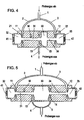
- FIG. 4 A first embodiment of a measuring cell according to the invention is shown in FIG. 4 exemplified in longitudinal section.
- the sample gas is fed into this measuring cell via a Sample gas line 1 is supplied, in the separate inlet lines 2 and 3 in two separate Tell streams split and from the inlets 2, 3 in the two outer ring channels 11 and 12 of the measuring cell out. From there, the partial flows pass radially through annular gaps 21 and 22 or radial channels in the measuring tube 31 and a coaxial, similarly sized Pipe 34, wherein the measuring tube 31 and the tube 34 through a chamber 33 with extended Cross-sectional area are separated from each other.
- the partial streams of the sample gas flow from on the outside through the Tellzellen 31 and 33, 34 to the center of the total cell, from where they pass through the annular gap 23 and the annular channel 13 flow into the outlet conduit 4.
- the sample gas flows away from the outer chambers 32, 35 with a larger cross-sectional area and away from the windows 41 and 42 required for the passage of the radiation Promotion of the sample gas flow can be achieved by a pump not shown here Measuring cell, or for example by the exhaust pressure in the exhaust system of a Internal combustion engine done.
- the "resonant" first subcell with a resonance tube 31 of length approximately ⁇ / 2 is obtained at a suitable period of radiation by known methods on the Resonance of the cell must be tuned, in the presence of absorbing substances in the sample gas a signal of the sensor microphone M, which has the same frequency as the Radiation and therefore by known means (e.g., the so-called “lock-in” technique and using e.g. a synchronous demodulator) very sensitive and selective can be detected.
- known means e.g., the so-called "lock-in” technique and using e.g. a synchronous demodulator
- the second Tellzelle consists of the segments 33, 34 with different Diameters and lengths of about ⁇ / 4, which is why in this subcell no with the Period of radiation can form resonant standing wave, as the specialist due to the underlying physical laws.
- the second subcell is non-resonant.
- belde can be used be performed resonantly.
- a Is arranged approximately ⁇ / 2 long Kompensadonsraum 33 with expanded diameter Is is the phase shift between the standing waves of the first subcell and the second tell cell about ⁇ , and the resulting phase shift is 2 ⁇ (or 360 °). It comes to a constructive (positive) superposition of the waves and the signal from Sensor microphone M in the measuring tube 31 of the "resonant" first tell cell is amplified.
- the Nachtell of this cell is the greater length, which not only increases the volume of construction, but also requires that the radiation must be bundled in parallel to better a longer length to maintain a sufficiently small beam diameter. A little Beam diameter Is absolutely necessary, because to avoid interference no Radiation may reach the walls of the narrow, long tubes 31,34 allowed.
- Fig. 6 The result of the finite element calculation of the flow in a cell according to Fig. 4 is shown in Fig. 6. Again, as for the figure for the state of Technique In Fig. 3, the direction and velocity of the flow through the direction and Length characterized by vectors. It is clear that neither a direct nor a Vortex flow to the windows exists. Also experimentally it has been confirmed that the Windows 41, 42 of this measuring cell pollute only slowly and comparatively slightly, allowing a long measurement time without cleaning the windows.
Landscapes
- Physics & Mathematics (AREA)
- General Physics & Mathematics (AREA)
- Pathology (AREA)
- Life Sciences & Earth Sciences (AREA)
- Chemical & Material Sciences (AREA)
- Analytical Chemistry (AREA)
- Biochemistry (AREA)
- Health & Medical Sciences (AREA)
- General Health & Medical Sciences (AREA)
- Immunology (AREA)
- Optics & Photonics (AREA)
- Acoustics & Sound (AREA)
- Investigating Or Analyzing Materials By The Use Of Ultrasonic Waves (AREA)
- Investigating Or Analysing Materials By Optical Means (AREA)
- Optical Measuring Cells (AREA)
- Measurement Of Radiation (AREA)
- Analysing Materials By The Use Of Radiation (AREA)
Abstract
Description
Claims (7)
- Messkammer für photoakustische Sensoren zur kontinuierlichen Messung von strahlungsabsorbierenden Substanzen, insbesondere von strahlungsabsorbierenden Partikeln, in gasförmigen Proben, mit zumindest einem Einlaß und zumindest einem Auslaß für die Proben, einem von der Probe in Längsrichtung durchströmbaren Rohrabschnitt mit Mikrophon, sowie mit zumindest einer mit dem Rohrabschnitt fluchtenden Eintritts- und Austrittsstelle für einen Laserstrahl, welche Eintritts- und Austrittsstelle durch zumindest jeweils eine Kammer mit gegenüber dem Rohrabschnitt erweiterten Querschnittsfläche vom Messrohr beabstandet sind, dadurch gekennzeichnet, dass zwei Einlässe (2, 3) an den einander gegenüberliegenden Enden des Rohrabschnittes (31) und zumindest ein Auslaß (4) an einer Stelle mittig zwischen den Einlässen vorgesehen sind.
- Messkammer nach Anspruch 1, dadurch gekennzeichnet, daß die Einlässe (2, 3) und/oder der zumindest eine Auslaß (4) in Ringkanäle (11, 12 bzw. 13) übergehen, die den Rohrabschnitt (31) koaxial umgeben, von weichen Ringkanälen radiale Einström- bzw. Ausströmkanäle zum Rohrabschnitt (31) verlaufen.
- Messkammer nach Anspruch 1, dadurch gekennzeichnet, daß die Einlässe (2, 3) und/oder der zumindest eine Auslaß (4) in Ringkanäle (11, 12 bzw. 13) übergehen, die den Rohrabschnitt (31) koaxial umgeben, von welchen Ringkanälen schmale Ringschlitze (21, 22 bzw. 23) zum Rohrabschnitt verlaufen.
- Messkammer nach einem der Ansprüche 1 bis 3, dadurch gekennzeichnet, daß ein Einlaß (2) und ein mittiger Auslaß (4) an den Enden einer resonanten Teilzelle (31) vorgesehen sind, welche durch jeweils eine Kammer (32, 33) mit gegenüber dem Rohrabschnitt (31) erweiterten Querschnittsfläche begrenzt ist, wobei sich der dem Auslaß (4) benachbarten Kammer (33) ein weiterer Rohrabschnitt (34) mit ähnlich großer Querschnittsfläche wie jener der resonanten Teilzelle (31) sowie eine weitere Kammer (35) mit gegenüber dem Rohrabschnitt (34) erweiterten Querschnittsfläche anschließen, und wobei der zweite Einlaß (3) am dem Auslaß (4) gegenüberliegenden Ende des weiteren Rohrabschnittes (34) vorgesehen ist.
- Messkammer nach Anspruch 4, dadurch gekennzeichnet, daß die Länge der mittleren Kammer (33) und des weiteren Rohrabschnittes (34) jeweils etwa die Hälfte der Länge des Rohrabschnittes (31) der resonanten Teilzelle beträgt.
- Messkammer nach einem der Ansprüche 1 bis 3, dadurch gekennzeichnet, daß ein Einlaß (2) und ein erster (4) von zwei mittigen Auslässen (4, 5) an den Enden einer resonanten Teilzelle (31) vorgesehen sind, welche durch jeweils eine Kammer (32, 33) mit gegenüber dem Rohrabschnitt (31) erweiterten Querschnittsfläche begrenzt ist, wobei sich der dem ersten Auslaß (4) benachbarten Kammer (33) ein weiterer Rohrabschnitt (34) mit ähnlich großer Querschnittsfläche und Länge wie jener der resonanten Teilzelle (31) sowie eine weitere Kammer (35) mit gegenüber dem Rohrabschnitt (34) erweiterten Querschnittsfläche anschließen, und wobei ein zweiter mittiger Auslaß (5) am sich an die mittige Kammer (33) anschließenden Ende des weiteren Rohrabschnittes (34) sowie der zweite Einlaß (3) am dem dem Auslaß (5) gegenüberliegenden Ende des weiteren Rohrabschnittes (34) vorgesehen ist.
- Messkammer nach Anspruch 6, dadurch gekennzeichnet, daß die Länge der mittleren Kammer (33) und des weiteren Rohrabschnittes (34) jeweils annähernd gleich der Länge der resonanten Teilzelle (31) sind.
Applications Claiming Priority (2)
| Application Number | Priority Date | Filing Date | Title |
|---|---|---|---|
| AT522004U | 2004-01-28 | ||
| AT0005204U AT6894U3 (de) | 2004-01-28 | 2004-01-28 | Messkammer für photoakustische sensoren |
Publications (3)
| Publication Number | Publication Date |
|---|---|
| EP1564543A2 true EP1564543A2 (de) | 2005-08-17 |
| EP1564543A3 EP1564543A3 (de) | 2005-08-24 |
| EP1564543B1 EP1564543B1 (de) | 2007-07-11 |
Family
ID=32046259
Family Applications (1)
| Application Number | Title | Priority Date | Filing Date |
|---|---|---|---|
| EP04450223A Expired - Lifetime EP1564543B1 (de) | 2004-01-28 | 2004-12-01 | Messkammer für einen photoakustischen Gassensor |
Country Status (7)
| Country | Link |
|---|---|
| US (1) | US7345766B2 (de) |
| EP (1) | EP1564543B1 (de) |
| JP (1) | JP4109262B2 (de) |
| CN (1) | CN100350234C (de) |
| AT (1) | AT6894U3 (de) |
| DE (1) | DE502004004284D1 (de) |
| DK (1) | DK1564543T3 (de) |
Cited By (3)
| Publication number | Priority date | Publication date | Assignee | Title |
|---|---|---|---|---|
| DE102006048839B4 (de) * | 2006-10-16 | 2010-01-07 | Eads Deutschland Gmbh | Photoakustische Gassensor-Vorrichtung mit mehreren Messzellen |
| WO2014090518A1 (de) | 2012-12-14 | 2014-06-19 | Avl List Gmbh | Fotoakustische messzelle |
| US8848191B2 (en) | 2012-03-14 | 2014-09-30 | Honeywell International Inc. | Photoacoustic sensor with mirror |
Families Citing this family (20)
| Publication number | Priority date | Publication date | Assignee | Title |
|---|---|---|---|---|
| CN101163956B (zh) * | 2005-04-26 | 2011-02-02 | 皇家飞利浦电子股份有限公司 | 用于含氮气体化合物检测的低成本设备 |
| DE102005030151B3 (de) * | 2005-06-28 | 2006-11-02 | Fraunhofer-Gesellschaft zur Förderung der angewandten Forschung e.V. | Photoakustischer Freifelddetektor |
| EP1962077A1 (de) * | 2007-02-21 | 2008-08-27 | IR Microsystems S.A. | Gassensor |
| DE102007043951B4 (de) * | 2007-09-14 | 2009-07-30 | Protronic Innovative Steuerungselektronik Gmbh | Vorrichtung zur Detektion von Molekülen in Gasen |
| EP2386733A1 (de) * | 2010-05-14 | 2011-11-16 | Schaller Automation Industrielle Automationstechnik GmbH & Co. KG | Anlage und Verfahren zum Ermitteln von Messwerten von Gasen und/oder eines Aerosols für eine Arbeitsmaschine |
| US20120118042A1 (en) * | 2010-06-10 | 2012-05-17 | Gillis Keith A | Photoacoustic Spectrometer with Calculable Cell Constant for Quantitative Absorption Measurements of Pure Gases, Gaseous Mixtures, and Aerosols |
| GB2484673A (en) * | 2010-10-18 | 2012-04-25 | Univ Dublin City | A photoacoustic inspection device |
| US20140026639A1 (en) * | 2012-07-30 | 2014-01-30 | General Electric Company | System and method for photoacoustic gas analysis |
| CN103266883A (zh) * | 2013-05-13 | 2013-08-28 | 中国石油天然气股份有限公司 | 一种油井中利用相对密度找水的方法及装置 |
| CN103983544B (zh) * | 2014-05-28 | 2015-12-30 | 南京大学 | 多通道气溶胶散射吸收测量仪 |
| DE102015117405A1 (de) * | 2015-10-13 | 2017-04-13 | Rbr Messtechnik Gmbh | Vorrichtung und Verfahren zur Messung der Feinstaubemissionen aus Feuerungen |
| WO2019014697A1 (de) | 2017-07-20 | 2019-01-24 | Avl List Gmbh | Photoakustische messvorrichtung mit resonatorelementen |
| CN111712704A (zh) * | 2017-12-15 | 2020-09-25 | ams有限公司 | 集成式热泳微粒物质传感器 |
| AT520793B1 (de) * | 2017-12-28 | 2021-02-15 | Avl List Gmbh | Messvorrichtung zur Ermittlung einer Messgröße eines Messgases |
| WO2020033046A1 (en) * | 2018-08-08 | 2020-02-13 | Applied Materials, Inc. | Method of gas composition determination, adjustment, and usage |
| CN109374529B (zh) * | 2018-09-13 | 2020-04-28 | 大连理工大学 | 一种半开腔共振式光声池 |
| EP3693725B1 (de) * | 2019-02-11 | 2021-04-07 | Infineon Technologies AG | Photoakustischer sensor |
| US11788965B2 (en) * | 2019-02-21 | 2023-10-17 | Arizona Board Of Regents On Behalf Of Arizona State University | Folic acid functionalized copper sulfide nanoparticles for the detection of ovarian cancer cells in flow |
| FR3108725B1 (fr) * | 2020-03-24 | 2022-03-25 | Commissariat Energie Atomique | Dispositif de détection d'un analyte par détection photoacoustique |
| CN116930091B (zh) * | 2023-09-14 | 2023-12-12 | 武汉理通微芬科技有限公司 | 基于非共振光声池的气体分析装置 |
Family Cites Families (11)
| Publication number | Priority date | Publication date | Assignee | Title |
|---|---|---|---|---|
| US4412445A (en) * | 1981-08-27 | 1983-11-01 | Optimetrics, Inc. | Resonant spectrophone system noise elimination |
| US4457162A (en) * | 1982-09-17 | 1984-07-03 | Institute Of Gas Technology | Multi-frequency photo-acoustic detector |
| CN1009489B (zh) * | 1985-06-15 | 1990-09-05 | 株式会社堀场制作所 | 光声效应式分析器 |
| US5069551A (en) * | 1989-11-24 | 1991-12-03 | Iowa State University Research Foundation, Inc. | Method and apparatus of measuring unburned carbon in fly ash |
| EP0456787B1 (de) * | 1989-12-08 | 1994-07-27 | OEHLER, Oscar, Dr. | Selektive gasdetektion durch feldseparation und schallgeschwindigkeitsmessung: sauerstoff-detektion |
| US5146283A (en) * | 1991-03-26 | 1992-09-08 | Andros Incorporated | Spectrophotometer sample cell |
| NO300078B1 (no) * | 1995-02-10 | 1997-04-01 | Sinvent As | Fotoakustisk gassdetektor |
| NL1007970C2 (nl) * | 1998-01-07 | 1999-07-08 | Stichting Tech Wetenschapp | Werkwijze voor het spectroscopisch bepalen van een vluchtige organische verbinding in een door een zoogdier afgegeven gas. |
| US6628397B1 (en) * | 1999-09-15 | 2003-09-30 | Kla-Tencor | Apparatus and methods for performing self-clearing optical measurements |
| DE10004816A1 (de) * | 2000-02-04 | 2001-08-09 | Hte Gmbh | Verfahren und Vorrichtung zur kombinatorischen Herstellung und Testung von Materialbibliotheken durch photoakustische Analysemethoden |
| US7034943B1 (en) * | 2000-03-03 | 2006-04-25 | Aritron Intrumente AG | Gas sensors |
-
2004
- 2004-01-28 AT AT0005204U patent/AT6894U3/de not_active IP Right Cessation
- 2004-12-01 DE DE502004004284T patent/DE502004004284D1/de not_active Expired - Lifetime
- 2004-12-01 DK DK04450223T patent/DK1564543T3/da active
- 2004-12-01 EP EP04450223A patent/EP1564543B1/de not_active Expired - Lifetime
- 2004-12-22 US US11/018,241 patent/US7345766B2/en not_active Expired - Lifetime
-
2005
- 2005-01-20 CN CNB2005100043879A patent/CN100350234C/zh not_active Expired - Lifetime
- 2005-01-25 JP JP2005017085A patent/JP4109262B2/ja not_active Expired - Lifetime
Cited By (3)
| Publication number | Priority date | Publication date | Assignee | Title |
|---|---|---|---|---|
| DE102006048839B4 (de) * | 2006-10-16 | 2010-01-07 | Eads Deutschland Gmbh | Photoakustische Gassensor-Vorrichtung mit mehreren Messzellen |
| US8848191B2 (en) | 2012-03-14 | 2014-09-30 | Honeywell International Inc. | Photoacoustic sensor with mirror |
| WO2014090518A1 (de) | 2012-12-14 | 2014-06-19 | Avl List Gmbh | Fotoakustische messzelle |
Also Published As
| Publication number | Publication date |
|---|---|
| US20050160800A1 (en) | 2005-07-28 |
| CN100350234C (zh) | 2007-11-21 |
| JP4109262B2 (ja) | 2008-07-02 |
| AT6894U3 (de) | 2005-01-25 |
| EP1564543A3 (de) | 2005-08-24 |
| DK1564543T3 (da) | 2007-08-06 |
| AT6894U2 (de) | 2004-05-25 |
| JP2005214973A (ja) | 2005-08-11 |
| US7345766B2 (en) | 2008-03-18 |
| EP1564543B1 (de) | 2007-07-11 |
| CN1654945A (zh) | 2005-08-17 |
| DE502004004284D1 (de) | 2007-08-23 |
Similar Documents
| Publication | Publication Date | Title |
|---|---|---|
| EP1564543B1 (de) | Messkammer für einen photoakustischen Gassensor | |
| EP2324329B1 (de) | Sensoranordnung zur bestimmung eines parameters eines fluiden mediums | |
| DE3883168T2 (de) | Verbesserungen bei Messaufnehmern mit einem einzigen schwingenden Rohr. | |
| DE69114670T2 (de) | Durchflussmesser für Fluide. | |
| DE69431873T2 (de) | Photoakustisches Analysegerät | |
| DE102010004513B4 (de) | Gaspartikelbehandlungssystem | |
| EP2103911B1 (de) | Strömungsmessung mit Ultraschall | |
| DE102015114047B4 (de) | Beheizte Strömungskonditionierungssysteme und Verfahren zu ihrer Anwendung | |
| AT517948B1 (de) | Kondensationspartikelzähler mit Flutungsschutz | |
| DE2730770C3 (de) | Ultraschallmeßvorrichtung zur Bestimmung der Strömungsgeschwindigkeit der Luft im Ansaugkanal einer Brennkraftmaschine | |
| DE3032633A1 (de) | Flussmessgeraet | |
| WO2009065613A1 (de) | Vorrichtung und messanordnung zur ermittlung der partikelkonzentration, der partikelgrösse, der mittleren partikelgrösse und der partikelgrössenverteilung der partikeln einer dispersen phase innerhalb eines dispersen systems sowie dessen trübung | |
| EP1227303A2 (de) | Ultraschalldurchflusszähler mit einer austauschbaren Messstrecke | |
| EP4182703B1 (de) | Durchflussmessgerät und verfahren zur messung des durchflusses eines fluids | |
| EP3537112A1 (de) | Fluiddurchflussmesser | |
| EP2215434B1 (de) | Sensoranordnung zur bestimmung eines parameters eines fluiden mediums | |
| DE102007030071B3 (de) | Ultraschall-Messvorrichtung | |
| EP2146189A1 (de) | Ultraschallmessung von Strömungsgeschwindigkeiten | |
| DE4133452A1 (de) | Vorrichtung zur dynamischen messung der partikeldichte in einer gasstroemung | |
| EP2064422B1 (de) | Vorrichtung zur abgasnachbehandlung und deren verwendung | |
| EP0762113B1 (de) | Vorrichtung zur Messung der Trübung von Rauchgas | |
| EP1818665A2 (de) | Partikelsensor | |
| DE102010029217A1 (de) | Vorrichtung zur Erfassung einer Eigenschaft eines strömenden fluiden Mediums | |
| DE102005051876B3 (de) | Fluidisch-akustischer Oszillator | |
| DE102010060929A1 (de) | Aeroakustischer Windkanal |
Legal Events
| Date | Code | Title | Description |
|---|---|---|---|
| PUAI | Public reference made under article 153(3) epc to a published international application that has entered the european phase |
Free format text: ORIGINAL CODE: 0009012 |
|
| PUAL | Search report despatched |
Free format text: ORIGINAL CODE: 0009013 |
|
| AK | Designated contracting states |
Kind code of ref document: A2 Designated state(s): AT BE BG CH CY CZ DE DK EE ES FI FR GB GR HU IE IS IT LI LT LU MC NL PL PT RO SE SI SK TR |
|
| AX | Request for extension of the european patent |
Extension state: AL BA HR LV MK YU |
|
| AK | Designated contracting states |
Kind code of ref document: A3 Designated state(s): AT BE BG CH CY CZ DE DK EE ES FI FR GB GR HU IE IS IT LI LT LU MC NL PL PT RO SE SI SK TR |
|
| AX | Request for extension of the european patent |
Extension state: AL BA HR LV MK YU |
|
| 17P | Request for examination filed |
Effective date: 20051107 |
|
| GRAP | Despatch of communication of intention to grant a patent |
Free format text: ORIGINAL CODE: EPIDOSNIGR1 |
|
| AKX | Designation fees paid |
Designated state(s): DE DK GB |
|
| GRAS | Grant fee paid |
Free format text: ORIGINAL CODE: EPIDOSNIGR3 |
|
| GRAA | (expected) grant |
Free format text: ORIGINAL CODE: 0009210 |
|
| AK | Designated contracting states |
Kind code of ref document: B1 Designated state(s): DE DK GB |
|
| REG | Reference to a national code |
Ref country code: GB Ref legal event code: FG4D Free format text: NOT ENGLISH |
|
| GBT | Gb: translation of ep patent filed (gb section 77(6)(a)/1977) |
Effective date: 20070711 |
|
| REG | Reference to a national code |
Ref country code: DK Ref legal event code: T3 |
|
| REF | Corresponds to: |
Ref document number: 502004004284 Country of ref document: DE Date of ref document: 20070823 Kind code of ref document: P |
|
| RIN2 | Information on inventor provided after grant (corrected) |
Inventor name: SCHINDLER, WOLFGANG, DR. Inventor name: HARMS, KLAUS-CHRISTOPH, DR. Inventor name: GRANTNER, HARALD, DIPL.-ING. (FH) Inventor name: KNOPF, FRANZ |
|
| PLBE | No opposition filed within time limit |
Free format text: ORIGINAL CODE: 0009261 |
|
| STAA | Information on the status of an ep patent application or granted ep patent |
Free format text: STATUS: NO OPPOSITION FILED WITHIN TIME LIMIT |
|
| 26N | No opposition filed |
Effective date: 20080414 |
|
| PGFP | Annual fee paid to national office [announced via postgrant information from national office to epo] |
Ref country code: DK Payment date: 20141219 Year of fee payment: 11 |
|
| REG | Reference to a national code |
Ref country code: DK Ref legal event code: EBP Effective date: 20151231 |
|
| PG25 | Lapsed in a contracting state [announced via postgrant information from national office to epo] |
Ref country code: DK Free format text: LAPSE BECAUSE OF NON-PAYMENT OF DUE FEES Effective date: 20151231 |
|
| P01 | Opt-out of the competence of the unified patent court (upc) registered |
Effective date: 20230502 |
|
| PGFP | Annual fee paid to national office [announced via postgrant information from national office to epo] |
Ref country code: GB Payment date: 20231218 Year of fee payment: 20 |
|
| PGFP | Annual fee paid to national office [announced via postgrant information from national office to epo] |
Ref country code: DE Payment date: 20231227 Year of fee payment: 20 |
|
| REG | Reference to a national code |
Ref country code: DE Ref legal event code: R071 Ref document number: 502004004284 Country of ref document: DE |
|
| REG | Reference to a national code |
Ref country code: GB Ref legal event code: PE20 Expiry date: 20241130 |
|
| PG25 | Lapsed in a contracting state [announced via postgrant information from national office to epo] |
Ref country code: GB Free format text: LAPSE BECAUSE OF EXPIRATION OF PROTECTION Effective date: 20241130 |
|
| PG25 | Lapsed in a contracting state [announced via postgrant information from national office to epo] |
Ref country code: GB Free format text: LAPSE BECAUSE OF EXPIRATION OF PROTECTION Effective date: 20241130 |