EP1564614A1 - Method and device for steering vehicle having no contact with track - Google Patents
Method and device for steering vehicle having no contact with track Download PDFInfo
- Publication number
- EP1564614A1 EP1564614A1 EP03770046A EP03770046A EP1564614A1 EP 1564614 A1 EP1564614 A1 EP 1564614A1 EP 03770046 A EP03770046 A EP 03770046A EP 03770046 A EP03770046 A EP 03770046A EP 1564614 A1 EP1564614 A1 EP 1564614A1
- Authority
- EP
- European Patent Office
- Prior art keywords
- steering angle
- steering
- rail
- control
- contact
- Prior art date
- Legal status (The legal status is an assumption and is not a legal conclusion. Google has not performed a legal analysis and makes no representation as to the accuracy of the status listed.)
- Granted
Links
Images




Classifications
-
- G—PHYSICS
- G05—CONTROLLING; REGULATING
- G05D—SYSTEMS FOR CONTROLLING OR REGULATING NON-ELECTRIC VARIABLES
- G05D1/00—Control of position, course, altitude or attitude of land, water, air or space vehicles, e.g. using automatic pilots
- G05D1/20—Control system inputs
- G05D1/24—Arrangements for determining position or orientation
- G05D1/244—Arrangements for determining position or orientation using passive navigation aids external to the vehicle, e.g. markers, reflectors or magnetic means
-
- B—PERFORMING OPERATIONS; TRANSPORTING
- B62—LAND VEHICLES FOR TRAVELLING OTHERWISE THAN ON RAILS
- B62D—MOTOR VEHICLES; TRAILERS
- B62D1/00—Steering controls, i.e. means for initiating a change of direction of the vehicle
- B62D1/24—Steering controls, i.e. means for initiating a change of direction of the vehicle not vehicle-mounted
- B62D1/26—Steering controls, i.e. means for initiating a change of direction of the vehicle not vehicle-mounted mechanical, e.g. by a non-load-bearing guide
- B62D1/265—Steering controls, i.e. means for initiating a change of direction of the vehicle not vehicle-mounted mechanical, e.g. by a non-load-bearing guide especially adapted for guiding road vehicles carrying loads or passengers, e.g. in urban networks for public transportation
-
- B—PERFORMING OPERATIONS; TRANSPORTING
- B62—LAND VEHICLES FOR TRAVELLING OTHERWISE THAN ON RAILS
- B62D—MOTOR VEHICLES; TRAILERS
- B62D1/00—Steering controls, i.e. means for initiating a change of direction of the vehicle
- B62D1/24—Steering controls, i.e. means for initiating a change of direction of the vehicle not vehicle-mounted
- B62D1/28—Steering controls, i.e. means for initiating a change of direction of the vehicle not vehicle-mounted non-mechanical, e.g. following a line or other known markers
-
- G—PHYSICS
- G05—CONTROLLING; REGULATING
- G05D—SYSTEMS FOR CONTROLLING OR REGULATING NON-ELECTRIC VARIABLES
- G05D1/00—Control of position, course, altitude or attitude of land, water, air or space vehicles, e.g. using automatic pilots
- G05D1/02—Control of position or course in two dimensions
- G05D1/021—Control of position or course in two dimensions specially adapted to land vehicles
- G05D1/0231—Control of position or course in two dimensions specially adapted to land vehicles using optical position detecting means
- G05D1/0234—Control of position or course in two dimensions specially adapted to land vehicles using optical position detecting means using optical markers or beacons
-
- G—PHYSICS
- G05—CONTROLLING; REGULATING
- G05D—SYSTEMS FOR CONTROLLING OR REGULATING NON-ELECTRIC VARIABLES
- G05D1/00—Control of position, course, altitude or attitude of land, water, air or space vehicles, e.g. using automatic pilots
- G05D1/60—Intended control result
- G05D1/646—Following a predefined trajectory, e.g. a line marked on the floor or a flight path
-
- G—PHYSICS
- G05—CONTROLLING; REGULATING
- G05D—SYSTEMS FOR CONTROLLING OR REGULATING NON-ELECTRIC VARIABLES
- G05D2101/00—Details of software or hardware architectures used for the control of position
- G05D2101/10—Details of software or hardware architectures used for the control of position using artificial intelligence [AI] techniques
Definitions
- the present invention relates to a steering apparatus for a rail non-contact vehicle and a steering method for the same, and more particularly to a steering apparatus for a rail non-contact vehicle, in which a steering operation is automated, and a steering method for the same.
- Adoption of a new transportation system is now promoted in narrow areas such as an airport and an exhibition site. Unlike Shinkansen bullet train as wide area transportation technology, the new transportation system is not required to transport in high speed and to carry out mass transportation, but is required not to need a large-scaled rail facility.
- a rubber tire type vehicle such as an automobile and a bus is known in Japanese Patent Laid Open Application (JP-P2002-310651A).
- the rubber tire type vehicle has a great degree of freedom on a running direction, and is not suitable for a vehicle in an airport.
- JP-P2002-19603A it is required to the new transportation system that a running route can be readily defined.
- Various techniques are known for a technology of a simple guide rail. Such guide rail requires a certain degree of strength for the safety operation. Securing the strength hinders desired reduction in facilities cost.
- a road surface side information belt having 1-dimensional coordinate data on a defined route is written with an operation data.
- the operation data includes a 1-dimensional coordinate data set on the running route.
- a table is necessary to indicate a corresponding relationship between the 1-dimensional coordinate data and an operation control data such as a steering angle, a velocity, and an acceleration. If the table value is fixed, it become difficult to carry out a control corresponding to a run situation that changes from moment to moment. Therefore, conventionally, a rapid velocity change resulted from a rapid change in a steering angle (for example, acceleration in a direction perpendicular to a rail direction) is caused, thereby, leading to aggravation of degree of comfort.
- An object of the present invention is to provide a steering apparatus for a rail non-contact vehicle and a steering method for the same, in which a technology is established of automating steering of the vehicle having no mechanical steering portion that contacts mechanically with a guide rail.
- Another object of the present invention is to provide a steering apparatus for a rail non-contact vehicle and a steering method for the same, in which a smooth operation can be accomplished by taking a future (predicted) variable into a control system.
- Still another object of the present invention is to provide a steering apparatus for a rail non-contact vehicle and a steering method for the same, in which an optimal control can be carried out through learning.
- a rail non-contact vehicle includes wheels, a vehicle main body supported by the wheels, and a steering control system.
- the steering control system includes a control section configured to control a steering of the wheels in a non-mechanical manner, and a drive section configured to mechanically drive the steering of the wheels.
- the control section includes a first detector configured to detect 1-dimensional coordinate data of a target route, a steering angle holding section configured to hold a target steering angle corresponding to the 1-dimensional coordinate data, a second detector configured to detect a current deviation between the target route and a current position of the vehicle main body, and a control steering angle calculating section configured to generate a control steering angle corresponding to the current deviation and the target steering angle.
- the current deviation is defined as a distance to the current position of the vehicle main body in a direction orthogonal to the target route, and the drive section turns an orientation of the wheels based on the control steering angle.
- the target route is preferably set on a road surface, and the second detector detects the position deviation in a non-contact manner.
- the rail non-contact vehicle may further include a calculating section provided on the vehicle main body.
- the calculating section calculates and holds a 2-dimensional coordinate data by integrating a velocity data of the vehicle main body.
- the target route is set on a road surface and may include an output section configured to output the 1-dimensional coordinate data, and the 1-dimensional coordinate data is transmitted to the first detector in wireless from the output portion.
- the target steering angle is preferably written in a running route.
- control section may further include a third detector configured to detect a velocity of the vehicle main body, and the steering angle control section generates a control data corresponding to the position deviation, the desired steering angle, and the velocity.
- control section may further include an optimization calculating section configured to optimize the control steering angle to an optimal solution, and the optimal solution is determined to minimize vibration resulting from the steering of the vehicle.
- control section may further include a steering angle correction controller configured to determine a future steering angle corresponding to a future position on the target route, and to generate a correction steering angle corresponding to the current deviation, the target steering angle, and the future steering angle.
- the control steering angle calculating section generates the control steering angle corresponding to the current deviation, the target steering angle, and the correction steering angle.
- control section may further include a second detector configured to detect the current steering angle to the current position when the vehicle carries out a N-th run of the target route, and an optimal solution calculating section configured to determine a current optimal target steering angle from all or a part of the current steering angles for N times.
- the optimal solution calculating section determines the current optimal target steering angle such that vibration resulting from the steering of the vehicle is minimized.
- the optimal solution calculating section may include a neural network configured to determine the correction steering angle. Instead, the optimal solution calculating section may execute a program to determine the correction steering angle based on genetic algorithm.
- the optimal solution calculating section preferably executes a program to determine the correction steering angle based on genetic algorithm.
- control section may further include an optimization calculating section configured to optimize a control data, and the optimization calculating section minimizes vibration resulting from the steering of the vehicle.
- the optimization calculating section determines the correction steering angle such that a square of the amplitudes is minimized.
- m and n take an optional one of a plurality of combinations of m and n
- an acceleration of the vehicle main body between the m-th run and the n-th run on the target route is expressed.
- the optimization calculating section determines the correction steering angle such that squares of the accelerations are minimized.
- the rail non-contact vehicle may further include a cart supported by the wheels, and a safety bar supported to the cart and configured to contact a rail side fixed object.
- the drive section is interposed between the cart and the wheels, and a displacement portion of the drive section is mechanically connected with the wheels and the safety bar.
- the displacement portion may be a ball screw driven by a motor or a nut connected to the ball screw.
- the displacement portion may be a cylinder driven with a fluid pressure source or a piston rod connected to the cylinder.
- a rail non-contact vehicle includes wheels, a cart supported by the wheels, and a steering apparatus.
- the steering apparatus includes a motor, a screw axis connected with an output axis of the motor, bearings configured to support the screw axis, a nut screwed with the screw axis, a first support configured to support the nut, a second support configured to support the bearings, and a link mechanism configured to steer the wheels.
- Either of the first support and the second support constitutes a fixation side support fixed to the cart, and either of the first support and the second support constitutes a movable side support connected with the link mechanism.
- the rail non-contact vehicle may further include a safety bar, and safe rings supported by the safety bar.
- the safety bar is connected with the movable side support
- the cart is connected with the fixation side support
- the nut is supported by the cart.
- the motor and the bearings are supported by the safety bar.
- the steering apparatus may further include a clutch interposed between the screw axis and the motor, and connection of the clutch is released in response to contact of the safe rings and the rail side fixed object.
- the nut is supported by the link mechanism, and the motor and the bearings are supported by the cart.
- the screw axis constitutes a ball screw axis.
- a rail non-contact vehicle in a third aspect of the present invention, includes wheels, a cart supported by the wheels, and a steering unit.
- the steering machine includes a motor, a movable body connected with an output axis of the motor, a safety bar provided with safe rings, and a link mechanism configured to steer the wheels.
- the link mechanism is connected with the safety bar and the movable body, and the safety bar is movably supported to the cart, and the motor is fixedly supported by the cart.
- the output axis of the motor may be connected with a movable body via a pinion and a rack.
- a rail non-contact vehicle in a fourth aspect of the present invention, includes wheels, a cart supported by the wheels, and a steering unit.
- the steering unit includes a motor, a screw axis connected with an output axis of the motor, bearings configured to support the screw axis, a nut screwed in the screw axis, a link mechanism configured to steer the wheels, and a safety bar provided with safe rings.
- the safety bar, the motor, and the bearings are fixedly supported by the cart, and the nut is connected with the link mechanism.
- the steering unit may further include a clutch interposed between the screw axis and the motor, and connection of the clutch is released in response to a contact of the safe rings and the rail side fixed object.
- a method of steering a rail non-contact vehicle is achieved by setting of a 1-dimensional coordinate data of a target route; by setting of a target steering angle corresponding to the 1-dimensional coordinate data X j ; by detecting a current deviation between the target routes and a current position of a vehicle main body; by generating a control steering angle corresponding to the current deviation and the target steering angle; and by turning orientation of wheels to an angle position corresponding to the control steering angle.
- the current deviation is defined as a distance of the current position in a direction orthogonal to the target route.
- the steering method may be achieved by further setting a future target steering corresponding to a future position on the target route; and by generating a correction steering angle corresponding to the future steering angle.
- the control steering angle is determined based on the current deviation, the target steering angle, and the correction steering angle.
- a sixth aspect of the present invention relates to a steering method of a rail non-contact vehicle, which comprise a drive section may include a motor, a ball screw axis connected with an output axis of the motor, and a nut connected with the ball screw axis, a clutch interposed between the motor and the ball screw axis, and a link mechanism connected with the wheels and configured to operate a rotation of the output axis of the motor.
- the steering method is achieved by detecting a contact between a part of the vehicle with a road surface side structure; and by disengaging the clutch interposed therebetween in response to the contact.
- the steering apparatus for a rail non-contact vehicle and the steering method thereof according to the present invention establishes a technique of automatic operation of a new transportation system, and dramatically improves smooth control performance, and thereby remarkably improves a degree of comfort.
- the steering apparatus mechanism using the ball screw axis reduces cost, simplifies the mechanism, and dramatically improves smooth control performance.
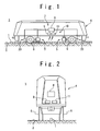
- Fig. 1 is a diagram showing the steering apparatus of the rail non-contact vehicle according to the first embodiment of the present invention.
- a guide line 1 is provided on a dedicated rail plane 2 to define a rail reference.
- the dedicated rail plane 2 is formed linearly or curvedly.
- the guide line 1 is shown in Fig. 1 such that it projects from the rail plane 2. However, the guide line 1 may be formed to be embedded in the rail plane 2.
- the vehicle 3 is provided with a vehicle main body 4 and a cart 5.
- the cart 5 is supported by the dedicated rail plane 2.
- the vehicle main body 4 is supported on the rail plane 2 by the cart 5 in such a manner that the vehicle main body 4 can turn freely around a perpendicular axis or an axis normal to the rail plane.
- the cart 5 is provided with wheels 6.
- the steering system is provided with a control section 10 as a non-mechanical steering system section, and a drive section 20 as a mechanical steering system section.
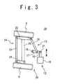
- the steering system is not provided with a mechanical guide rail by which the vehicle 3 is mechanically guided, as shown in Fig. 2. It is not essential that the vehicle 3 mechanically contacts with the guide line 1.
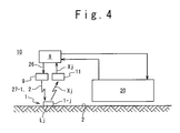
- Fig. 3 shows a drive section 20.
- the drive section 20 includes an actuator 12, a first link mechanism 13, and a second link mechanism 14.
- the actuator 12 has an actuator main body 15 as an unmovable part, and a piston rod 16 as a movable part.
- the actuator main body 15 is fixed to the cart 5.
- the first link mechanism 13 is provided with a first link 17 and a second link 18.
- the base side of the first link 17 is rotatably supported by the cart 5 by a first pin 19. Free end of the first link 17 is rotatably connected with the operation end of the piston rod 16 by a second pin 21.
- the second link mechanism 14 is provided with a first lever 22 rotatably supported by the cart 5, a lever link 23, and a second lever 24 rotatably supported by the cart 5.
- the free end of the second link 18 is rotatably connected to one end of the first lever 22.
- the other end of the first lever 22 is rotatably connected to one end of the lever link 23.
- the other end of the lever link 23 is rotatably connected to one end of the second lever 24.
- the piston rod 16 moves forward and backward in a linearly manner.
- the first link 17 is rotated to angularly displace in accordance with the linear displacement of the piston rod 16.
- the second link mechanism 14 operates.
- the first lever 22 of the second link mechanism 14 is rotated in accordance with a composite movement of a rotating operation and a linear moving operation of the second link 18.
- a center line of a shaft 25 passes through the wheels 6 of the both sides of the cart, and the wheels 6 are rotatably supported by the shaft 25 in a plane parallel to the dedicated rail plane 2.
- the shaft 25 is supported by the cart 5.
- the first lever 22, the second link mechanism 14, the second lever 24, and the axle 25 form a 4-coupling link mechanism of a parallelogram. Therefore, the parallelogram is transformed in accordance with the composite movement of the second link 18, and the planes (vertical planes) at the both ends orthogonal to the rotation axis 25 of the wheel 6 is rotated to the axle 25 to be parallel each other.
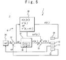
- Fig. 4 shows a relation between the control section 10 and the drive section 20.
- the control section 10 is provided with the guide line 1 and a steering control section 7.
- the steering control section 7 is provided with a control unit 8, a transmitting unit 9, and a receiving unit 11.
- the control unit 8 transmits a data acquisition command signal 26 to the transmitting unit 9.
- the transmitting unit 9 sends a data acquisition operation signal 27 in response to the data acquisition command signal 26.
- the data acquisition operation signal 27 includes a data transmitting request signal 27-1.
- the data acquisition operation signal 27 may include power 27-2 to be supplied. A ground side power supply which supplies power to the guide line 1 is not necessary when the supplied power 27-2 is used.
- the guide line 1 is divided into sections between a start point and a terminal point in a same interval, and has a sequence of position data X j for the sections.
- the sequence of position data X j expresses the sequence of the 1-dimensional curved coordinates.
- the guide line 1 is a circular guide line
- the coordinate of the terminal point is identical to the coordinate of the start point. It is preferred that the interval is no more than one cm.
- the 1-dimensional curved coordinate X is strictly defined on a 3-dimensional absolute coordinate system.
- the sequence of the one-dimensional curved coordinates X of the guide line 1 is a sequence of line formation elements 1-j. Each line formation element 1-j corresponds to the 1-dimensional position coordinate (position data) X j .
- the line formation element 1-j sends the position data X j , a target steering angle ⁇ *(X j ), and a target rail deviation ⁇ R* in response to the data transmitting request signal 27-1.
- the receiving unit 11 receives the position data X j , the target steering angle ⁇ *(X j ), and the target rail deviation ⁇ R* and transfers them to the control unit 8. It is effective that the line formation element 1-j has an operation control data such as a 3-dimensional absolute coordinate value and a 3-dimensional defined velocity value corresponding to the position data X j .
- a 3-dimensional rail curvature and a 3-dimensional acceleration can be calculated from the 3-dimensional absolute coordinate and the 3-dimensional defined velocity.
- a table (the position data X j , the target steering angle, the target rail deviation, the target velocity, the target acceleration, the rail curvature).
- a table may be provided for the line formation element 1-j, or provided for the control unit 8.
- the table is contained with the target steering angle, the target rail deviation, the target velocity, the target acceleration, and the rail curvature corresponding to the element 1-j.
- the target steering angle, the target rail deviation, the target velocity, the target acceleration, and the rail curvature are searched based upon the position data X j .
- Fig. 5 shows the details of the steering control section 7.
- the steering control section 7 carries out a control operation based on a 4-dimensional coordinate system.
- Time coordinate is defined based on an internal clock (not shown).
- Space coordinate is defined based on a 3-dimensional coordinate.
- the rail reference curve expressed with 1-dimensional curved coordinate system is set within the 3-dimensional coordinate system.
- the steering control section 7 is provided with the control unit 8, a rail deviation measuring unit 33, and a steering angle detector 34.
- the control unit 8 is provided with a rail deviation setting unit 36, a subtraction unit 37, a steering angle prediction correction controller 38, a main controller 31 containing a steering angle calculation section 35, and a correction adding unit 32.
- the rail deviation setting unit 36 sets the target rail deviation ⁇ R*(X j ) received through the receiving unit 11 from the guide line 1.
- the target rail deviation ⁇ R* is set as an ideal value or target value ⁇ R*(X j ) for the position data X j .
- the target rail deviation ⁇ R*(X j ) is not always zero.
- the target rail deviation ⁇ R*(X j ) can be set to zero on a straight line rail. However, it is ideal in a rail region which the rail changes from a straight line rail to a curved rail that the centrifugal force inertia of the vehicle is taken into consideration. In this case, the vehicle runs on an actual rail that is set outer than the guide line 1.
- the target rail deviation ⁇ R*(X j ) is set as a distance between such an ideal rail and the guide line 1.
- the target rail deviation ⁇ R*(X j ) is a constant value of zero.
- the receiving unit 11 is arranged as a detector which detects the position data X j in a reference point of the vehicle 3. It is preferred for such reference point to be set on rotation axis of the vehicle main body 4 with respect to the cart.
- the receiving unit 11 receives the target steering angle ⁇ *(X j ) which is fixedly defined in the guide line 1 to output to the steering angle calculation section 35.
- the rail deviation measuring unit 33 is arranged in the reference point, and measures a current rail deviation ⁇ R in the direction normal to the guide line (a direction orthogonal to the rail or a curvature-radius direction).
- a CCD camera is preferred as a rail deviation measuring unit 33.
- the CCD camera takes photos of the guide line 1.
- the rail deviation measuring unit 33 calculates a distance between an optical axis of the CCD camera, and the guide line picked-up as a real image. Therefore, the current rail deviation ⁇ R corresponds to the calculated distance.
- the current rail deviation ⁇ R is supplied to the subtraction unit 37.
- the steering angle detector 34 detects a quantity of movement of the piston rod 16 to the actuator main body 15 of the actuator 12 as a current steering angle ⁇ (X j ) in real-time.
- the current steering angle ⁇ (X j ) is output to the steering angle prediction correction controller 38.
- the subtraction unit 37 is interposed between the rail deviation setting unit 36 and the steering angle calculation section 35.
- the target rail deviation ⁇ R*(X j ) is supplied to the subtraction unit 37 together with the current rail deviation ⁇ R(X j ).
- the control rail deviation ⁇ R'(X j ) is supplied as a feedback control signal to the steering angle calculation section 35 and the steering angle prediction correction controller 38.
- the steering angle calculation section 35 sets the target steering angle ⁇ *(X j ) for the position data X j received by the receiving unit 11.
- the data fixedly defined in the guide line 1 is supplied through the receiving unit 11 to the steering angle calculation section 35.
- the target steering angle ⁇ *(X j ) may be defined as a table (X j , ⁇ *(X j )) in the steering angle calculation section 35.
- the main controller 31 determines a provisional control steering angle ⁇ '(X j ) which is obtained by weighting the control rail deviation ⁇ R'(X j ) and the target steering angle ⁇ *(X j ) with a rate of 2 to 1.
- the provisional control steering angle ⁇ '(X j ) is supplied to the correction adding unit 32.
- the correction adding unit 32 receives the provisional control steering angle ⁇ '(X j ) from the steering angle calculation section 35, receives a correction steering angle ⁇ *(X j ) from the steering angle prediction correction controller 38, and adds the correction steering angle ⁇ *(X j ) to the provisional control steering angle ⁇ '(X j ). Thus, a target control steering angle ⁇ "(X j ) is generated. The target control steering angle ⁇ "(X j ) is output to the actuator 12 of the vehicle 3. In this way, a rudder is controlled.
- the steering angle prediction correction controller 38 receives the control rail deviation ⁇ R' outputted from the subtraction unit 37.
- the steering angle prediction correction controller 38 receives and holds the current steering angle ⁇ (X j ) measured by the steering angle detector 34.
- the controller 38 generates an index from the current steering angles ⁇ (X j ) for N times corresponding to the identical position of the guide line 1 in the past operation, and holds the index as an operation history steering angle ⁇ (X j , [N]).
- the best operation in the numerous operation records is experientially determined based on questionnaires collected from passengers, real riding experience of specialists, and real operation of an expert (although the steering unit for an operator does not exist, the operator can generate a steering angle signal from a terminal input unit).
- the steering angle prediction correction controller 38 has an optimal target steering angle ⁇ **(X j ).
- the optimal target steering angle ⁇ **(X j ) expresses a suitable steering angle in each position of the guide line 1. Therefore, the steering angle prediction correction controller 38 has the current optimal target steering angle ⁇ **(X j ) to the current position X j of the vehicle, and a future optimal target steering angle ⁇ **(X j + ⁇ X j ) when the vehicle advances from the current position X j to a future position (X j + ⁇ X j ) by ⁇ X j .
- the ⁇ X j is set as a function of the variable j of the current position X j , and may be set based on a future rail curvature of the guide line 1. In that case, when a change rate in the curvature between the current position X j and the future position (X j + ⁇ X j ) is small, the ⁇ X j is set larger. Also, when the change rate of the curvature is large, the ⁇ X j is set smaller.
- the steering angle prediction correction controller 38 calculates a correction steering angle ⁇ *(X j ) by weighting the control rail deviation ⁇ R', the current optimal target steering angle ⁇ **(X j ), and the future optimal target steering angle ⁇ **(X j + ⁇ X j ) with the rate of 3 to 1.
- the calculated correction steering angle ⁇ *(X j ) is supplied to the adding unit 32.
- the optimal target steering angle ⁇ **(X j ) may be determined based upon the operation history steering angle ⁇ (X j [N]). It is preferable to determine the optimal target steering angle ⁇ **(X j ) in such a way that the vibration resulting from steering of the vehicle be minimized.
- a table regarding the current position X j is provided and the optimal target steering angle ⁇ **(X j ) may be searched from the table.
- a velocity sensor (not shown) is provided for the vehicles 3
- the velocity V of the vehicle may be received from a velocity sensor.
- the 2-dimensional coordinate position of the vehicle is calculated through integration of the velocity.
- the rail deviation setting unit 36 and the steering angle calculation section 35 use the target rail deviation ⁇ R*(X j ) and the target steering angle ⁇ *(X j ) that correspond to the current position of the vehicle 3. It takes time for the data to be able to be outputted after setting. In actual, there might be a case where the output may be possible when the vehicle 3 progresses to a position of X j+1 . In such a case, the target rail deviation ⁇ R* (X j-1 ) and the target steering angle ⁇ * (Xj -1 ) that are prior to the current position of the vehicle by one element may be used.
- the steering angle prediction correction controller 38 carries out an optimal control calculation to determine the optimal correction steering angle ⁇ **(X j ).
- the optimal control calculation is possible by a learning calculation, or a dynamic equation calculation, or by a combination of these two calculations.
- the learning calculation it is preferred to use a neural network calculation or a genetic algorithm calculation, or a genetic algorithm calculation in which the neural network calculation is incorporated.
- the neural network calculation and the genetic algorithm calculation are commonly known as a calculation technique.
- the dynamic equation calculation it is preferred to use the minimum square value calculation (4-dimensional navigation) with respect to acceleration among the rails which shortcut passage candidate points by the inverse dynamics of the dynamic equation of the 4-dimensional coordinates.
- the 4-dimensional navigation is known as an optimal route discovery technique for airplane.
- the control rail deviation ⁇ R', the current steering angle ⁇ *(X j ), and the future optimal steering angle ⁇ **(X j + ⁇ X j ) are inputted to the input side of the neural network as a learning data under a constraint condition in which these data are smaller than setting threshold values. Also, the correction steering angle ⁇ *(X j ) corresponding to those data is inputted to the output side of the neural network as a teacher data.
- the current optimal target steering angle ⁇ **(X j ) and the future optimal target steering angle ⁇ **(X j + ⁇ X j ) are expressed as a current optimal target steering angle ⁇ **(X j ) and a future optimal target steering angle ⁇ **(X j+1 ), respectively.
- Each of nodes of the neural network has coefficients k1, k2, k3 and k4.
- the coefficient is generally a function of coordinate X j .
- the neural network learns many combinations of the learning data and the teacher data.
- the optimal solution of the coefficients can be gradually and approximately determined by giving many combinations (y, x) under the constraint condition (the least sum of second powers of accelerations, or the least sum of second powers of amplitudes).
- the constraint condition the least sum of second powers of accelerations, or the least sum of second powers of amplitudes.
- the constraint condition is to express a distance deviation between the vehicle body positions in the identical position in the m-th operation and the n-th operation (m and n are not equal) as an amplitude Ws, and to take a plurality of different sets of values as m and n.
- Ws a distance deviation between the vehicle body positions in the identical position in the m-th operation and the n-th operation (m and n are not equal)
- the constraint condition is to express accelerations of the vehicle body in the identical position in the m-th operation and the n-th operation as Am, and to take a plurality of different sets of values as m and n.
- Am accelerations of the vehicle body in the identical position in the m-th operation and the n-th operation
- the genetic algorithm is a method in which the control rail deviation ⁇ R', the current optimal steering angle ⁇ **(X j ), the future optimal steering angle ⁇ **(X j + ⁇ X j ), and the correction steering angle ⁇ *(X j ) are selected as unknown variables locally and globally in a random, and a solution asymptotically converges toward the optimal solution while trap into a local solution is avoided.
- An estimation function is set for the optimization.
- the estimation function is similar to a case of the neural network. A variable factor, of which the estimation function value is low but is not determined to be not selected, is selected.
- a rail is determined as a solution for the dynamic equation having an initial condition to every time and the acceleration at the time as known values.
- the velocity and/or acceleration is determined as a solution of the dynamic equation having the rail coordinates X j as an unknown value.
- a proximity to coordinate X j received from the guide line 1 is permitted as a coordinate X i of the vehicle 3 on the rail.
- Such constraint condition is given as a minimization of the square sum of the acceleration, or minimization of a sum of the second powers of acceleration deviations, and the shortest time to reach a destination.
- the constraint condition as minimization of acceleration gives a priority to a degree of comfort and mathematically defines velocity and/or acceleration.
- the acceleration solved in real time through inverse dynamics and the velocity at that time correspond to a ratio of 2 to 1 in a steering angle.
- the solution calculated in this way may be supplied to the output side of the above-mentioned neural network as the teacher data.
- the correction steering angle ⁇ *(X j ) obtained thus is outputted to the correction adding unit 32 from the steering angle prediction correction controller 38.
- the provisional control steering angle ⁇ '(X j ) is zero.
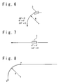
- Fig. 6 shows the ideal running state on a circular rail where the curvature radius R is constant.
- Fig. 7 shows the ideal running state on a straight line rail where the curvature radius R ideally infinite.
- the actuator 12 instantly changes a steering angle from zero to a defined steering angle ⁇ ' at the point P.
- a predetermined steering angle ⁇ * corresponding to the constant curvature rail is set in the steering angle calculation section 35.
- the correction steering angle ⁇ * (X j ) is zero at the point P
- the control steering angle ⁇ "(X j ) is equal to the provisional control steering angle ⁇ '(X j ). It is ideal that the correction steering angle ⁇ *(X j ) smoothly increases thereafter, becomes maximum at the middle point between the point P and a point Q, smoothly decreases after passing through the middle point, and becomes zero at the point Q.
- the steering angle change per unit clock further corresponds to the difference between the current steering angle ⁇ (X j ) and the current defined target steering angle ⁇ *(X j ), or particularly may be proportional.
- k1 and k2, and k3 and k4 to be described below are the coefficients of the nodes in the neural network.
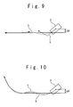
- the curvature change of the curved rail of the near future instead of the best rail b as shown Fig. 9 is fed forward, i.e., predicted and fed in advance, and the correction steering angle ⁇ * (X j ) is outputted from the steering angle prediction correction controller 38 to the correction adding unit 32 for the vehicle to smoothly approximate the future curvilinear rail.
- a non-contacting type guide rail 41 is provided instead of the guide line 1 in the control section 10 of the second embodiment of the present invention.
- the guide rail 41 is provided with a rail bottom 42, a curbstone 43, and a pair of central guide rails 44.
- the wheels 6 on the both sides of the vehicle are supported by the central guide rails 44 to rotate.
- position detecting sensors 45 are fixedly arranged respectively.
- a position detecting sensor 45 corresponds to a pair of the transmitting unit 9 and the receiving unit 11 as described above.
- the position detecting sensor 45 is a non-contacting type sensor such as a CCD camera and an automatic focal position focusing laser.
- the position detecting sensor 45 detects the relative location between the line edge 46 of the central guide rail 44 and the vehicle main body 4. When the vehicle 3 is in a normal position, the position detecting sensor 45 generates an image in which the line edge 46 is coincident with the central line of the CCD camera.
- the position detecting sensor 45 detects a position deviation ⁇ D as a distance between the central line of the CCD camera and the line edge 46.
- the position deviation ⁇ D is supplied to the steering angle calculation section 35 and the steering angle prediction correction controller 38 of the control unit 8 as the above-mentioned ⁇ R'. As shown in Fig.
- the position detecting sensor 45 may be arranged fixedly to the side wall of the vehicle main body 4. In this case, the position detecting sensor 45 detects the distance or the distance deviation between a reference surface of the side wall of the vehicle main body 4 and the inner surface of the curbstone 43.
- a difference ⁇ R' between a preset value ⁇ R and the position deviation ⁇ D may be supplied to the steering angle calculation section 35 and the steering angle prediction correction controller 38 of the control unit 8 as shown in the first embodiment.
- the position detecting sensor 45 in the third embodiment of the present invention is fixedly arranged at the head section of the upper section of the vehicle 3.
- An optical axis 47 of the position detecting sensor 45 intersects the road surface 2 at a predetermined angle ⁇ .
- the distance L between intersection 48 of the optical axis 47 and the road surface 2 and the reference point of the vehicle 3 is constant.
- the CCD camera when the CCD camera is used as the position detecting sensor 45, the width W between rail belt signs 51 drawn or embedded on the road surface 2 as a rail surface is detected as a width at a relative location defined for the distance L.
- the CCD camera detects the distance deviation ⁇ W between the reference point P set on the image and the central point of the width W.
- the deviation ⁇ W is processed similarly to the position deviation ⁇ D in the second embodiment.
- the guide line 1 has a single rail belt sign 51 in the fourth embodiment of the present invention.
- a reference image 52 with a reference width W is set on the image by the CCD camera.
- the rail belt sign 51 picked-up by the CCD camera and the reference image 52 are superimposed to produce three different kinds of images with width W1, W2 and WO.
- W W1 + WO + W.
- safe guide rings 53 are added to the vehicle 3 of the Fig. 12 in the fifth embodiment of the present invention.
- the safe guide ring 53 is provided on either side of the main body of the vehicle 3 or the cart 5.
- a rotation shaft 54 of the safe guide ring 53 is parallel to the opposing surface of the curbstone 43 on either side.
- the safe guide ring 53 does not contact the curbstone 43.
- the construction cost of the safe guide ring 53 which does not contact the curbstone 43 is significantly lower compared with the construction cost of the well-known guide rail for guide rails.
- a rotation frequency detector (not shown) which detects the number of rotations of the wheel 6.
- An absolute position data on the one-dimensional curved coordinate L of the cart 5 or the vehicle 3 and a relative location data between the cart 5 or the vehicle 3 and the guide line 1 are added as control data.
- the absolute position data may be measured by a measuring unit in a kinetic system.
- the absolute position data may be acquired from the guide line 1 (ubiquitous sensor).
- FIG. 17 the drive section 20 of a four-guide-ring type bogie according to the sixth embodiment of the present invention will be described.
- four guide rings 101 in contact with a guide rail are supported at the right and left ends of the parallel isometric link 102, and the right and left wheels 6 are supported at both ends of the shaft 25.
- the front and rear parallel isometric links 102 are connected with a link 103.
- the link 103 and the shaft 25 are intersectingly connected at both middle points, and an intersection 104 is rotatably supported by the cart 5.
- the guide ring 101, the parallel isometric link 102, and the link 103 are removed, and the actuator 12 is connected with the shaft 25.
- the technique of the four guide ring bogie type is still adopted, but the guide rings 101 re arranged in such a way that they are not in contact with the curbstone 43.
- the drive section 20 of the steering system used in the steering apparatus of the rail non-contact vehicle according to the seventh embodiment of the present invention will be described.
- the present embodiment realizes the above-mentioned real time high precision route control and the safety associated with the control.
- the feature is achieved by using a ball screw and a safety bar, and adding a safe clutch.
- the drive section 20 is provided with the actuator 12, the first link mechanism 13, and the second link mechanism 14.
- An actuator fixed section 55 fixedly supported by the cart 5 is equivalent to the above-mentioned actuator main body 15.
- An actuator movable section 56 which moves forward and backward to the actuator fixed section 55 is equivalent to the above-mentioned piston rod 16.
- a nut 57 is fixed to the actuator fixed section 55.
- a ball screw 58 screwed in the nut 57 is rotatably supported by bearings 60 and 61 which are fixed to the actuator movable section 56.
- a servomotor 59 is fixedly arranged in the actuator movable section 56.
- the end of the ball screw 58 is connected via a coupling 62 with an output axis 63 of the servomotor 59.
- a clutch 64 is interposed in the output axis 63.
- the safety bar 65 is connected with the actuator movable section 56, and moves forward and backward in a transverse direction d. At the both ends of the safety bar 65, safe rings 66 are rotatably attached.
- One end of the first link mechanism 13 is rotatably supported by the cart 5, and the other end of the first link mechanism 13 is supported by the safety bar 65 rotatably to the cart 5.
- the servomotor 59 receives the above-mentioned target control steering angle ⁇ "(X j ) and rotates to a rotation position corresponding to the target steering angle.
- the ball screw 58 rotates to a corresponding rotation position, and moves to a linear position corresponding to the rotation position in response to the reaction from the nut 57.
- the actuator movable section 56 that linearly moves together with the ball screw 58 displaces the first link mechanism 13 and the second link mechanism 14.
- the lever link 23 displaces in response to the linear displacement of the second link mechanism 14 and rotates and drives the wheels 6 to the steering angle position corresponding to the target control steering angle ⁇ "(X j ).
- the safe rings 66 on the right and left sides are not in contact with the safe guide (the curbstone 43 in Fig. 16).
- the control rail deviation ⁇ R' shows an abnormally large value because there is a gust or the contact with another vehicle in an airport so that the vehicle comes off the guide line 1
- the safe rings 66 of the vehicle 3 on the right and left sides contact the curbstone 43.
- the impelling force of the vehicle in the above-mentioned automatic control is influenced with the reaction received from the curbstone 43. For this reason, the control position of the ball screw 58 and the actual position become different, and the difference between them is detected by the servomotor 61.
- the drive source of the vehicle 3 is a diesel engine, a hybrid system of an electric motor and a diesel engine, or a fuel cell.
- the use of the ball screw 58 makes control response accuracy higher and safety can be promptly secured at the time of abnormalities.
- the curbstone 43 has almost no function to support and guide the vehicle, but only supports the vehicle for a short period during which the control rail deviation ⁇ R' is detected and the vehicle stops. For this reason, the curbstone 43 needs almost no needs for strength, therefore the construction cost are made remarkably cheap.
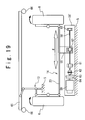
- Fig. 19 shows a modification of the seventh embodiment shown in Fig. 18.
- the actuator movable section 56 is changed into an actuator fixed section 56'.
- the actuator fixed section 56' is fixed to the cart 5.
- the nut 57 is movably supported to the actuator fixed section 56' by the ball screw 58.
- the bearings 60, the servomotor 59, the coupling 62, the output axis 63, and the clutch 64 are arranged in the actuator fixed section 56' just as similarly as the one shown in the seventh embodiment.
- the end section of the first link mechanism 13 is rotatably supported by the cart 5, and another end of the first link mechanism 13 is rotatably supported by the safety bar 65.
- the displacement of the safety bar 65 when the vehicle separates from the rail and contacts the curbstone 43, is transmitted to the wheel 6 via the first link mechanism 13 and the second link mechanism 14, the wheel 6 is steered corresponding to the curbstone 43, and the clutch 64 is instantly disengaged.
- the embodiment of Fig. 19 is relatively identical with the seventh embodiment of Fig. 18.
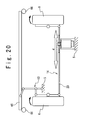
- FIG. 20 the drive section 20 of the steering system used for the steering apparatus of the rail non-contact vehicle according to the eighth embodiment of the present invention will be described.
- this embodiment uses a rack and pinion pair instead of the above-mentioned ball screw and nut pair.
- This embodiment shows less performance with respect to the steering accuracy, however, excels in reduction of the cost of the drive section compared with the aforementioned embodiment.
- FIG. 21 the drive section 21 of the steering system used for the steering apparatus of the rail non-contact vehicle according to the ninth embodiment of the present invention will be described.
- this embodiment differs to the embodiment of Fig. 19 in that the safety bar 65 is directly fixed to the cart 5 without the first link mechanism 13.
- the clutch 64 is disengaged at the time of abnormalities, and the vehicle 3 is directly guided by the safe rings 66 of the safety bar 65 of the right and left sides.
- the nut 57 which non-resistively and freely moves in a transverse direction d to the ball screw 58 does not behave as an obstacle for steering.
- the safety bar for guiding the vehicle 3 is actually not required since the vehicle main body itself has a function of the safety bar.
- An abnormal torque occurs in the servomotor 61 when the vehicle main body contacts the curbstone 43, and a control signal expressing a control steering angle is sent normally to the servomotor 61. Detection of the abnormal torque stops the further movement of the vehicle and actuates the braking of the wheel 6 to prevent accident.
- the drive section 20 of the steering system used for the steering apparatus of the rail non-contact vehicle according to the tenth embodiment of the present invention will be described.
- this embodiment realizes the above-mentioned real time high precision route control and the safety associated with the control.
- the feature is achieved by using a fluid pressure drive mechanism and the safety bar.
- the fluid pressure drive mechanism is used instead of the drive section 20 in the seventh embodiment of Fig. 18 which uses the screw axis.
- a fluid pressure supply source (not shown) is used instead of the motor 59, and a piston rod 57' is used instead of a pair of the nut 57 and the ball screw 58.
- the pressured fluid supplied to the inside of a fluid pressure cylinder 71 acts on movable end of the piston rod 57' on one side, and the movable end of the piston rod 57' on the other side is fixed to the actuator fixed section 55 which is fixedly supported by the cart 5.
- a steering mechanism supplies positive pressure or negative pressure to the operation chamber 72 of the fluid pressure cylinder 71, drives the safety bar 65 in right and left directions to the actuator fixed section 55, and actuates the first link mechanism 13 and the second link mechanism 14 via the safety bar 65.
- the control of the steering mechanism is similar to the control of the seventh embodiment of Fig. 18 in a point that the turn direction of the wheels is controlled via movement of the safety bar 65.
- the safety bar 65 moves in right and left directions when the positive and negative pressure oil is supplied to the operation chamber of the fluid pressure cylinder 71. It would be theoretically possible that when the safety bar 65 receives external force from the outside of the vehicle, the external force and the supply capability of the oil pressure to the fluid pressure cylinder 71 interfere with each other.
- the steering control of the control section 10 is inactivated and the auxiliary mechanical control by the safety bar 65, the first link mechanism 13, and the second link mechanism 14 is carried out with a priority.
- the momentary interference at the time of switching of the control is eased by viscosity and compressibility of fluid of the fluid pressure cylinder.
- an open valve interposed in piping of the fluid pressure control mechanism opens, and safety is thoroughly maintained. Due to such a buffer mechanism, this embodiment excels in safety than the seventh embodiment of Fig. 18.
- air pressure is preferable as the fluid pressure
- water is preferable as the fluid concerning environment.
- the ball screw 58 of Fig. 19 may be replaced by the piston rod 57' of Fig. 18.
- the ball screw 58 of Fig. 21 may be replaced by the piston rod 57' of Fig. 18.
- the actuator movable section 56 and the actuator fixed section 55 of Fig. 22 are exchangeable in position.
- the actuator movable section 56 may be fixed to the cart 5, and the actuator fixed section 55 to the safety bar 65.
Landscapes
- Engineering & Computer Science (AREA)
- Physics & Mathematics (AREA)
- Combustion & Propulsion (AREA)
- Transportation (AREA)
- Mechanical Engineering (AREA)
- Chemical & Material Sciences (AREA)
- Automation & Control Theory (AREA)
- Radar, Positioning & Navigation (AREA)
- Remote Sensing (AREA)
- General Physics & Mathematics (AREA)
- Aviation & Aerospace Engineering (AREA)
- Electromagnetism (AREA)
- Steering Control In Accordance With Driving Conditions (AREA)
- Automobile Manufacture Line, Endless Track Vehicle, Trailer (AREA)
- Platform Screen Doors And Railroad Systems (AREA)
- Power Steering Mechanism (AREA)
- Control Of Position, Course, Altitude, Or Attitude Of Moving Bodies (AREA)
Abstract
Description
Claims (31)
- A rail non-contact vehicle comprising:wherein said steering control system comprises:wheels;a vehicle main body supported by said wheels; anda steering control system,said control section comprises:a control section configured to control a steering of said wheels in a non-mechanical manner; anda drive section configured to mechanically drive the steering of said wheels,said current deviation is defined as a distance to said current position of said vehicle main body in a direction orthogonal to said target route, anda first detector configured to detect 1-dimensional coordinate data of a target route;a steering angle holding section configured to hold a target steering angle corresponding to said 1-dimensional coordinate data;a second detector configured to detect a current deviation between said target route and a current position of said vehicle main body; anda control steering angle calculating section configured to generate a control steering angle corresponding to said current deviation and said target steering angle,
said drive section turns an orientation of said wheels based on said control steering angle. - The rail non-contact vehicle according to claim 1, wherein said target route is set on a road surface, and said second detector detects said position deviation in a non-contact manner.
- The rail non-contact vehicle according to claim 1, further comprising:wherein said calculating section calculates and holds a 2-dimensional coordinate data by integrating a velocity data of said vehicle main body.a calculating section provided on said vehicle main body, and
- The rail non-contact vehicle according to claim 1, wherein said target route is set on a road surface and comprises an output section configured to output said 1-dimensional coordinate data, and
said 1-dimensional coordinate data is transmitted from said output portion to said first detector in wireless. - The rail non-contact vehicle according to claim 4, wherein said target steering angle is written in a running route.
- The rail non-contact vehicle according to claim 1, wherein said control section further comprises:a third detector configured to detect a velocity of said vehicle main body, anda steering angle control section generates a control data corresponding to said position deviation, said desired steering angle, and said velocity.
- The rail non-contact vehicle according to claim 1, wherein said control section further comprises:an optimization calculating section configured to optimize said control steering angle to an optimal solution, andsaid optimal solution is determined to minimize vibration resulting from the steering of said vehicle.
- The rail non-contact vehicle according to claim 1, wherein said control section further comprises:a steering angle correction controller configured to determine a future steering angle corresponding to a future position on said target route, and to generate a correction steering angle corresponding to said current deviation, said target steering angle, and said future steering angle, andsaid control steering angle calculating section generates said control steering angle corresponding to said current deviation, said target steering angle, and said correction steering angle.
- The rail non-contact vehicle according to claim 8, wherein said control section further comprises:a second detector configured to detect said current steering angle to said current position when said vehicle carries out a N-th run of said target route; andan optimal solution calculating section configured to determine a current optimal target steering angle from all or a part of said current steering angles for N times, andsaid optimal solution calculating section determines said current optimal target steering angle such that vibration resulting from the steering of said vehicle is minimized.
- The rail non-contact vehicle according to claim 9, wherein said optimal solution calculating section comprises a neural network configured to determine said correction steering angle.
- The rail non-contact vehicle according to claim 9, wherein said optimal solution calculating section executes a program to determine said correction steering angle based on genetic algorithm.
- The rail non-contact vehicle according to claim 11, wherein said optimal solution calculating section executes a program to determine said correction steering angle based on genetic algorithm.
- The rail non-contact vehicle according to claim 8, wherein said control section further comprises:an optimization calculating section configured to optimize a control data, andsaid optimization calculating section minimizes vibration resulting from the steering of said vehicle.
- The rail non-contact vehicle according to claim 13, wherein when m and n take an optional one of a plurality of combinations of m and n, a deviation between a position of said vehicle main body at a m-th run and an n-th run on said target route is expressed as an amplitude, and
said optimization calculating section determines said correction steering angle such that a sum of squares of the amplitudes is minimized. - The rail non-contact vehicle according to claim 13, wherein when m and n take an optional one of a plurality of combinations of m and n, an acceleration of said vehicle main body between the m-th run and the n-th run on said target route is expressed, and
said optimization calculating section determines said correction steering angle such that a sum of squares of the accelerations is minimized. - The rail non-contact vehicle according to any of claims 1 to 15, further comprising:said drive section is interposed between said cart and said wheels, anda cart supported by said wheels; anda safety bar supported by said cart and configured to contact a rail side fixed object,
a displacement portion of said drive section is mechanically connected with said wheels and said safety bar. - The rail non-contact vehicle according to claim 16, wherein said displacement portion is a ball screw driven by a motor or a nut connected to said ball screw.
- The rail non-contact vehicle according to claim 16, wherein said displacement portion is a cylinder driven with a fluid pressure source or a piston rod connected to said cylinder.
- A rail non-contact vehicle comprising:wherein said steering apparatus comprises:wheels;a cart supported by said wheels; anda steering apparatus, anda motor;a screw axis connected with an output axis of said motor;bearings configured to support said screw axis;a nut screwed with said screw axis;a first support configured to support said nut;a second support configured to support said bearings; anda link mechanism configured to steer said wheels, andeither of said first support and said second support constitutes a fixation side support fixed to said cart, and either of said first support and said second support constitutes a movable side support connected with said link mechanism.
- The rail non-contact vehicle according to claim 19, further comprising:said safety bar is connected with said movable side support,a safety bar; andsafe rings supported by the safety bar, and
said cart is connected with said fixation side support, and
said nut is supported by the cart. - The rail non-contact vehicle according to claim 19, wherein said motor and said bearings are supported by said safety bar.
- The rail non-contact vehicle according to claim 20 or 21, wherein said steering apparatus further comprises:a clutch interposed between said screw axis and said motor, andconnection of said clutch is released in response to contact of said safe rings and said rail side fixed object.
- The rail non-contact vehicle according to claim 19, wherein said nut is supported by said link mechanism, and said motor and said bearings are supported by said cart.
- The rail non-contact vehicle according to any of claims 19 to 23, wherein said screw axis constitutes a ball screw axis.
- A rail non-contact vehicle comprising:said steering machine comprises:wheels;a cart supported by said wheels, anda steering unit, andsaid link mechanism is connected with said safety bar and said movable body, anda motor;a movable body connected with an output axis of said motor;a safety bar provided with safe rings, anda link mechanism configured to steer said wheels,
said safety bar is movably supported to said cart, and said motor is fixedly supported by said cart. - The rail non-contact vehicle according to claim 25, wherein said output axis of said motor is connected with a movable body via a pinion and a rack.
- A rail non-contact vehicle comprising:wherein steering unit comprises:wheels;a cart supported by said wheels; anda steering unit, andsaid safety bar, said motor, and said bearings are fixedly supported by said cart, anda motor;a screw axis connected with an output axis of said motor; bearings configured to support said screw axis;a nut screwed in said screw axis;a link mechanism configured to steer said wheels; anda safety bar provided with safe rings,
said nut is connected with said link mechanism. - The rail non-contact vehicle according to claim 27, wherein said steering unit further comprises:a clutch interposed between said screw axis and said motor, andconnection of said clutch is released in response to a contact of said safe rings and said rail side fixed object.
- A method of steering a rail non-contact vehicle, comprising:wherein said current deviation is defined as a distance of said current position in a direction orthogonal to said target route.setting of a 1-dimensional coordinate data of a target route;setting of a target steering angle corresponding to said 1-dimensional coordinate data Xj;detecting a current deviation between said target routes and a current position of a vehicle main body;generating a control steering angle corresponding to said current deviation and said target steering angle; andturning orientation of wheels to an angle position corresponding to said control steering angle, and
- The steering method according to claim 29, further comprising:wherein said control steering angle is determined based on said current deviation, said target steering angle, and said correction steering angle.setting a future target steering corresponding to a future position on said target route; andgenerating a correction steering angle corresponding to the future steering angle, and
- A steering method of a rail non-contact vehicle, wherein a drive section comprises a motor, a ball screw axis connected with an output axis of said motor, and a nut connected with the ball screw axis, a clutch interposed between said motor and said ball screw axis, and a link mechanism connected with said wheels and configured to operate a rotation of the output axis of said motor,
said steering method further comprises:detecting a contact between a part of said vehicle with a road surface side structure; anddisengaging said clutch interposed therebetween in response to the contact.
Applications Claiming Priority (3)
| Application Number | Priority Date | Filing Date | Title |
|---|---|---|---|
| JP2002316559 | 2002-10-30 | ||
| JP2002316559 | 2002-10-30 | ||
| PCT/JP2003/013953 WO2004040391A1 (en) | 2002-10-30 | 2003-10-30 | Method and device for steering vehicle having no contact with track |
Publications (3)
| Publication Number | Publication Date |
|---|---|
| EP1564614A1 true EP1564614A1 (en) | 2005-08-17 |
| EP1564614A4 EP1564614A4 (en) | 2006-11-29 |
| EP1564614B1 EP1564614B1 (en) | 2010-03-03 |
Family
ID=32211687
Family Applications (1)
| Application Number | Title | Priority Date | Filing Date |
|---|---|---|---|
| EP03770046A Expired - Lifetime EP1564614B1 (en) | 2002-10-30 | 2003-10-30 | Method and device for steering vehicle having no contact with track |
Country Status (11)
| Country | Link |
|---|---|
| US (1) | US7757608B2 (en) |
| EP (1) | EP1564614B1 (en) |
| JP (1) | JP4347221B2 (en) |
| KR (1) | KR100802275B1 (en) |
| AT (1) | ATE459523T1 (en) |
| AU (1) | AU2003280653A1 (en) |
| CA (2) | CA2641261C (en) |
| DE (1) | DE60331575D1 (en) |
| ES (1) | ES2339547T3 (en) |
| TW (1) | TWI266713B (en) |
| WO (1) | WO2004040391A1 (en) |
Cited By (3)
| Publication number | Priority date | Publication date | Assignee | Title |
|---|---|---|---|---|
| FR2919399A1 (en) * | 2007-07-23 | 2009-01-30 | Raoul Parienti | AUTOMATED COLLECTIVE TRANSPORT SYSTEM. |
| EP2045163A4 (en) * | 2006-11-01 | 2012-03-21 | Mitsubishi Heavy Ind Ltd | Track-type traffic system |
| US8209091B2 (en) | 2007-07-19 | 2012-06-26 | Mitsubishi Heavy Industries, Ltd. | Method of and apparatus for controlling steering of a vehicle |
Families Citing this family (21)
| Publication number | Priority date | Publication date | Assignee | Title |
|---|---|---|---|---|
| JP4751399B2 (en) | 2004-11-02 | 2011-08-17 | リサーチ イン モーション リミテッド | Generic access network (GAN) controller selection in PLMN environment |
| DE102005003063A1 (en) * | 2005-01-22 | 2006-08-03 | Framatome Anp Gmbh | Method and device for determining the deviation of a along an actual path translationally guided body of a desired path |
| JP4370266B2 (en) * | 2005-01-28 | 2009-11-25 | 三菱重工業株式会社 | Steering mechanism of track system |
| JP4370267B2 (en) * | 2005-01-28 | 2009-11-25 | 三菱重工業株式会社 | Bifurcation mechanism of track-type traffic system and steering method of branch road |
| JP4370281B2 (en) * | 2005-05-20 | 2009-11-25 | 三菱重工業株式会社 | Track structure of track system vehicle |
| US7987026B2 (en) * | 2007-07-01 | 2011-07-26 | Yu-Meng Yi | Railroad track model servomotor type control system |
| KR101221766B1 (en) * | 2007-07-19 | 2013-01-16 | 미츠비시 쥬고교 가부시키가이샤 | Control device of track-based vehicle and track-based vehicle having the same |
| JP5357696B2 (en) * | 2009-10-21 | 2013-12-04 | 三菱重工業株式会社 | Rail-type vehicle having a guide device |
| DE102009053457A1 (en) * | 2009-11-16 | 2011-05-19 | Siemens Aktiengesellschaft | Operating device and method for its operation |
| JP5738165B2 (en) | 2011-12-19 | 2015-06-17 | 三菱重工業株式会社 | Transportation system |
| TW201415032A (en) * | 2012-10-01 | 2014-04-16 | China Engineering Consultants Inc | Space track curvature inversion method |
| US20140142868A1 (en) * | 2012-11-18 | 2014-05-22 | Andian Technologies Ltd. | Apparatus and method for inspecting track in railroad |
| US9821824B2 (en) | 2013-01-29 | 2017-11-21 | Mitsubishi Heavy Industries, Ltd. | Vehicle and track transportation system |
| CN115855022A (en) | 2017-04-07 | 2023-03-28 | 辉达公司 | Perform Autonomous Path Navigation Using Deep Neural Networks |
| US10705525B2 (en) | 2017-04-07 | 2020-07-07 | Nvidia Corporation | Performing autonomous path navigation using deep neural networks |
| US10604184B2 (en) * | 2017-08-31 | 2020-03-31 | Ford Global Technologies, Llc | Adaptive steering control for robustness to errors in estimated or user-supplied trailer parameters |
| JP7212538B2 (en) * | 2018-03-09 | 2023-01-25 | 三菱重工業株式会社 | steering control system, steering system, vehicle, steering control method and program |
| US11203353B2 (en) | 2018-03-09 | 2021-12-21 | Mitsubishi Heavy Industries, Ltd. | Steering control system, steering system, car, steering control method and recording medium |
| TWI685436B (en) * | 2018-05-31 | 2020-02-21 | 萬業科技股份有限公司 | System and method for measuring track flatness |
| JP7531262B2 (en) * | 2019-03-22 | 2024-08-09 | 三菱重工業株式会社 | Position detection system, vehicle, and position detection method |
| JP2022079156A (en) * | 2020-11-16 | 2022-05-26 | 株式会社フォーラムエイト | Driving simulation device and driving simulation program |
Family Cites Families (36)
| Publication number | Priority date | Publication date | Assignee | Title |
|---|---|---|---|---|
| JPS61143817A (en) | 1984-12-12 | 1986-07-01 | Toshiba Corp | Automatic moving device |
| JPH04257006A (en) | 1991-02-12 | 1992-09-11 | Toyota Autom Loom Works Ltd | Course out detecting method for unmanned vehicle |
| JP2678102B2 (en) | 1991-06-19 | 1997-11-17 | 株式会社新潟鉄工所 | Guideway steering device for vehicles in guideway system |
| JPH05184178A (en) * | 1992-01-09 | 1993-07-23 | Nissan Motor Co Ltd | Actuator controlling device |
| JPH06119034A (en) * | 1992-10-01 | 1994-04-28 | Daifuku Co Ltd | Mobile vehicle travel control device |
| JP3266747B2 (en) * | 1994-11-10 | 2002-03-18 | 株式会社小松製作所 | Vehicle guidance and travel control device |
| JPH08150949A (en) * | 1994-11-28 | 1996-06-11 | Mazda Motor Corp | Vehicle running control device |
| JPH08272442A (en) * | 1995-03-31 | 1996-10-18 | Mitsubishi Motors Corp | Vehicle steering angle calculator |
| JPH08339226A (en) * | 1995-06-13 | 1996-12-24 | Meidensha Corp | Automated guided vehicle control device |
| JP3465462B2 (en) | 1996-02-01 | 2003-11-10 | トヨタ自動車株式会社 | Vehicle steering system |
| JPH09282032A (en) * | 1996-04-10 | 1997-10-31 | Daifuku Co Ltd | Mobile vehicle guidance equipment |
| JPH1069219A (en) * | 1996-08-28 | 1998-03-10 | Honda Motor Co Ltd | Automatic traveling road and automatic traveling system |
| JP3378766B2 (en) * | 1997-05-19 | 2003-02-17 | 日本輸送機株式会社 | Unmanned vehicle steering control method |
| US6185492B1 (en) | 1997-07-09 | 2001-02-06 | Toyota Jidosha Kabushiki Kaisha | Vehicle steering control apparatus for assisting a steering effort to move a vehicle along a line desired by a driver |
| FR2766782B1 (en) * | 1997-07-31 | 1999-10-01 | Renault Vehicules Ind | GUIDANCE SYSTEM FOR PUBLIC TRANSPORT VEHICLE |
| JP3316841B2 (en) * | 1998-08-06 | 2002-08-19 | 村田機械株式会社 | Automatic guided vehicle system |
| DE19837340B4 (en) | 1998-08-18 | 2005-12-29 | Daimlerchrysler Ag | Steering system in a vehicle equipped with a tracking device |
| JP2000172336A (en) * | 1998-09-29 | 2000-06-23 | Toyota Motor Corp | Guideway traffic system and self-driving vehicle used in the system |
| JP3863303B2 (en) * | 1998-10-19 | 2006-12-27 | 住友重機械工業株式会社 | Moving body position measuring device |
| JP2000264196A (en) | 1999-03-12 | 2000-09-26 | Toyota Motor Corp | Self-driving vehicles used in guideway traffic systems |
| JP2000302055A (en) | 1999-04-20 | 2000-10-31 | Honda Motor Co Ltd | Lane tracking controller |
| JP2001010518A (en) * | 1999-06-25 | 2001-01-16 | Honda Motor Co Ltd | Vehicle steering control device |
| JP3694423B2 (en) | 1999-06-25 | 2005-09-14 | 本田技研工業株式会社 | Vehicle and steering control device for vehicle |
| JP3649065B2 (en) * | 1999-11-19 | 2005-05-18 | トヨタ自動車株式会社 | Brake hydraulic pressure control device for vehicles |
| JP2001265436A (en) * | 2000-03-17 | 2001-09-28 | Toyota Motor Corp | Moving object traveling system, moving object traveling control device, and marker setting method |
| JP3517833B2 (en) * | 2000-04-05 | 2004-04-12 | 本田技研工業株式会社 | Vehicle having variable steering angle ratio steering device and electric power steering device |
| JP4231910B2 (en) | 2000-04-25 | 2009-03-04 | 日産自動車株式会社 | Lane keeping device |
| JP3539362B2 (en) * | 2000-07-07 | 2004-07-07 | 日産自動車株式会社 | Lane following travel control device |
| JP2002019603A (en) | 2000-07-10 | 2002-01-23 | Toyota Motor Corp | Travel guide device for autonomous vehicles |
| JP2002180860A (en) * | 2000-10-02 | 2002-06-26 | Denso Corp | Vehicle integrated control system |
| JP2002123315A (en) * | 2000-10-13 | 2002-04-26 | Nippon Yusoki Co Ltd | Magnetic induction line |
| JP2002312034A (en) | 2001-04-12 | 2002-10-25 | Sanyo Electric Co Ltd | Self-driving car |
| JP2002310651A (en) | 2001-04-17 | 2002-10-23 | Nippon Telegr & Teleph Corp <Ntt> | Ecological research system and method |
| GB2374682A (en) | 2001-04-17 | 2002-10-23 | Paolo Niccolai | An automatic vehicle control system |
| JP4575620B2 (en) * | 2001-05-17 | 2010-11-04 | 東北電力株式会社 | Automatic vehicle transfer system |
| JP4638078B2 (en) | 2001-05-22 | 2011-02-23 | 三菱重工業株式会社 | Vehicle steering system and steering method |
-
2003
- 2003-10-30 CA CA2641261A patent/CA2641261C/en not_active Expired - Fee Related
- 2003-10-30 CA CA2504621A patent/CA2504621C/en not_active Expired - Fee Related
- 2003-10-30 WO PCT/JP2003/013953 patent/WO2004040391A1/en not_active Ceased
- 2003-10-30 AT AT03770046T patent/ATE459523T1/en not_active IP Right Cessation
- 2003-10-30 DE DE60331575T patent/DE60331575D1/en not_active Expired - Lifetime
- 2003-10-30 EP EP03770046A patent/EP1564614B1/en not_active Expired - Lifetime
- 2003-10-30 US US10/532,932 patent/US7757608B2/en not_active Expired - Lifetime
- 2003-10-30 JP JP2004548091A patent/JP4347221B2/en not_active Expired - Fee Related
- 2003-10-30 ES ES03770046T patent/ES2339547T3/en not_active Expired - Lifetime
- 2003-10-30 TW TW092130291A patent/TWI266713B/en not_active IP Right Cessation
- 2003-10-30 KR KR1020057007457A patent/KR100802275B1/en not_active Expired - Lifetime
- 2003-10-30 AU AU2003280653A patent/AU2003280653A1/en not_active Abandoned
Cited By (8)
| Publication number | Priority date | Publication date | Assignee | Title |
|---|---|---|---|---|
| EP2045163A4 (en) * | 2006-11-01 | 2012-03-21 | Mitsubishi Heavy Ind Ltd | Track-type traffic system |
| US8234022B2 (en) | 2006-11-01 | 2012-07-31 | Mitsubishi Heavy Industries, Ltd. | Track transportation system |
| US8209091B2 (en) | 2007-07-19 | 2012-06-26 | Mitsubishi Heavy Industries, Ltd. | Method of and apparatus for controlling steering of a vehicle |
| FR2919399A1 (en) * | 2007-07-23 | 2009-01-30 | Raoul Parienti | AUTOMATED COLLECTIVE TRANSPORT SYSTEM. |
| WO2009044003A1 (en) * | 2007-07-23 | 2009-04-09 | Raoul Parienti | Automated collective transport system |
| CN102112934A (en) * | 2007-07-23 | 2011-06-29 | 劳欧·帕瑞堤 | Automated Public and Personal Transportation Systems |
| JP2011528833A (en) * | 2007-07-23 | 2011-11-24 | パリエンティ,ラウル | Automated public and personal transport systems |
| CN102112934B (en) * | 2007-07-23 | 2015-07-01 | 劳欧·帕瑞堤 | Automated Public and Personal Transportation Systems |
Also Published As
| Publication number | Publication date |
|---|---|
| HK1081675A1 (en) | 2006-05-19 |
| US7757608B2 (en) | 2010-07-20 |
| KR20050065639A (en) | 2005-06-29 |
| ATE459523T1 (en) | 2010-03-15 |
| KR100802275B1 (en) | 2008-02-11 |
| JPWO2004040391A1 (en) | 2006-03-02 |
| ES2339547T3 (en) | 2010-05-21 |
| DE60331575D1 (en) | 2010-04-15 |
| WO2004040391A1 (en) | 2004-05-13 |
| US20060200280A1 (en) | 2006-09-07 |
| JP4347221B2 (en) | 2009-10-21 |
| CA2641261C (en) | 2011-04-26 |
| CA2641261A1 (en) | 2004-05-13 |
| EP1564614B1 (en) | 2010-03-03 |
| EP1564614A4 (en) | 2006-11-29 |
| TWI266713B (en) | 2006-11-21 |
| CA2504621A1 (en) | 2004-05-13 |
| TW200415056A (en) | 2004-08-16 |
| CA2504621C (en) | 2011-06-14 |
| AU2003280653A1 (en) | 2004-05-25 |
Similar Documents
| Publication | Publication Date | Title |
|---|---|---|
| EP1564614B1 (en) | Method and device for steering vehicle having no contact with track | |
| EP3575173B1 (en) | A vehicle with autonomous driving capability | |
| US9796416B2 (en) | Automated driving apparatus and automated driving system | |
| US6519514B2 (en) | Automatic travel control apparatus for vehicle | |
| EP4049916B1 (en) | Vehicle control method, vehicle control system, and vehicle | |
| CN106394650B (en) | Field-Based Torque Steering Control | |
| CN115023380A (en) | Asymmetrical fail-safe system architecture | |
| CN106950964B (en) | Unmanned electric formula student car and its control method | |
| US20180284801A1 (en) | Universal autonomous robotic driving system | |
| US20080059015A1 (en) | Software architecture for high-speed traversal of prescribed routes | |
| CN102227612A (en) | Controls and systems for autonomous vehicles | |
| Liu et al. | Lateral control of an autonomous and connected following vehicle with limited preview information | |
| Leedy et al. | Virginia Tech's twin contenders: A comparative study of reactive and deliberative navigation | |
| US20250162601A1 (en) | Estimation of driver interaction based tuning parameters for automated driving or driver assistance | |
| HK1081675B (en) | Method and device for steering vehicle having no contact with track | |
| Kim et al. | Deep learning-based heading angle estimation for enhanced autonomous vehicle backward driving control | |
| EP3977722B1 (en) | Electric vehicle with autonomous drive | |
| Schein | Optimal Vehicle Control of Four-Wheel Steering | |
| JP7113056B2 (en) | Vehicles with autonomous driving capabilities | |
| KR20170098381A (en) | Line tracking method of automatic guided vehicle equipped with the omnidirectional drive wheel | |
| Redmill et al. | Ohio state university experiences at the darpa challenges | |
| EP4733175A1 (en) | Steering arrangement for robotic vehicle | |
| CN109131019A (en) | Model animal automates toter and method | |
| Peiris et al. | All-wheel steering and driving control of an 8x8 scaled electric combat vehicle | |
| Wang et al. | Research on precise control of hydraulic truck path navigation |
Legal Events
| Date | Code | Title | Description |
|---|---|---|---|
| PUAI | Public reference made under article 153(3) epc to a published international application that has entered the european phase |
Free format text: ORIGINAL CODE: 0009012 |
|
| 17P | Request for examination filed |
Effective date: 20050429 |
|
| AK | Designated contracting states |
Kind code of ref document: A1 Designated state(s): AT BE BG CH CY CZ DE DK EE ES FI FR GB GR HU IE IT LI LU MC NL PT RO SE SI SK TR |
|
| AX | Request for extension of the european patent |
Extension state: AL LT LV MK |
|
| DAX | Request for extension of the european patent (deleted) | ||
| REG | Reference to a national code |
Ref country code: HK Ref legal event code: DE Ref document number: 1081675 Country of ref document: HK |
|
| A4 | Supplementary search report drawn up and despatched |
Effective date: 20061027 |
|
| RIC1 | Information provided on ipc code assigned before grant |
Ipc: B62D 1/28 20060101AFI20061023BHEP |
|
| 17Q | First examination report despatched |
Effective date: 20070412 |
|
| GRAP | Despatch of communication of intention to grant a patent |
Free format text: ORIGINAL CODE: EPIDOSNIGR1 |
|
| GRAS | Grant fee paid |
Free format text: ORIGINAL CODE: EPIDOSNIGR3 |
|
| GRAA | (expected) grant |
Free format text: ORIGINAL CODE: 0009210 |
|
| AK | Designated contracting states |
Kind code of ref document: B1 Designated state(s): AT BE BG CH CY CZ DE DK EE ES FI FR GB GR HU IE IT LI LU MC NL PT RO SE SI SK TR |
|
| REG | Reference to a national code |
Ref country code: GB Ref legal event code: FG4D |
|
| REG | Reference to a national code |
Ref country code: CH Ref legal event code: EP |
|
| REG | Reference to a national code |
Ref country code: IE Ref legal event code: FG4D |
|
| REF | Corresponds to: |
Ref document number: 60331575 Country of ref document: DE Date of ref document: 20100415 Kind code of ref document: P |
|
| REG | Reference to a national code |
Ref country code: ES Ref legal event code: FG2A Ref document number: 2339547 Country of ref document: ES Kind code of ref document: T3 |
|
| REG | Reference to a national code |
Ref country code: NL Ref legal event code: VDEP Effective date: 20100303 |
|
| REG | Reference to a national code |
Ref country code: HK Ref legal event code: GR Ref document number: 1081675 Country of ref document: HK |
|
| PG25 | Lapsed in a contracting state [announced via postgrant information from national office to epo] |
Ref country code: SI Free format text: LAPSE BECAUSE OF FAILURE TO SUBMIT A TRANSLATION OF THE DESCRIPTION OR TO PAY THE FEE WITHIN THE PRESCRIBED TIME-LIMIT Effective date: 20100303 Ref country code: AT Free format text: LAPSE BECAUSE OF FAILURE TO SUBMIT A TRANSLATION OF THE DESCRIPTION OR TO PAY THE FEE WITHIN THE PRESCRIBED TIME-LIMIT Effective date: 20100303 Ref country code: FI Free format text: LAPSE BECAUSE OF FAILURE TO SUBMIT A TRANSLATION OF THE DESCRIPTION OR TO PAY THE FEE WITHIN THE PRESCRIBED TIME-LIMIT Effective date: 20100303 |
|
| PG25 | Lapsed in a contracting state [announced via postgrant information from national office to epo] |
Ref country code: CY Free format text: LAPSE BECAUSE OF FAILURE TO SUBMIT A TRANSLATION OF THE DESCRIPTION OR TO PAY THE FEE WITHIN THE PRESCRIBED TIME-LIMIT Effective date: 20100303 Ref country code: BE Free format text: LAPSE BECAUSE OF FAILURE TO SUBMIT A TRANSLATION OF THE DESCRIPTION OR TO PAY THE FEE WITHIN THE PRESCRIBED TIME-LIMIT Effective date: 20100303 Ref country code: RO Free format text: LAPSE BECAUSE OF FAILURE TO SUBMIT A TRANSLATION OF THE DESCRIPTION OR TO PAY THE FEE WITHIN THE PRESCRIBED TIME-LIMIT Effective date: 20100303 Ref country code: SE Free format text: LAPSE BECAUSE OF FAILURE TO SUBMIT A TRANSLATION OF THE DESCRIPTION OR TO PAY THE FEE WITHIN THE PRESCRIBED TIME-LIMIT Effective date: 20100303 Ref country code: NL Free format text: LAPSE BECAUSE OF FAILURE TO SUBMIT A TRANSLATION OF THE DESCRIPTION OR TO PAY THE FEE WITHIN THE PRESCRIBED TIME-LIMIT Effective date: 20100303 Ref country code: GR Free format text: LAPSE BECAUSE OF FAILURE TO SUBMIT A TRANSLATION OF THE DESCRIPTION OR TO PAY THE FEE WITHIN THE PRESCRIBED TIME-LIMIT Effective date: 20100604 Ref country code: EE Free format text: LAPSE BECAUSE OF FAILURE TO SUBMIT A TRANSLATION OF THE DESCRIPTION OR TO PAY THE FEE WITHIN THE PRESCRIBED TIME-LIMIT Effective date: 20100303 |
|
| PG25 | Lapsed in a contracting state [announced via postgrant information from national office to epo] |
Ref country code: SK Free format text: LAPSE BECAUSE OF FAILURE TO SUBMIT A TRANSLATION OF THE DESCRIPTION OR TO PAY THE FEE WITHIN THE PRESCRIBED TIME-LIMIT Effective date: 20100303 Ref country code: CZ Free format text: LAPSE BECAUSE OF FAILURE TO SUBMIT A TRANSLATION OF THE DESCRIPTION OR TO PAY THE FEE WITHIN THE PRESCRIBED TIME-LIMIT Effective date: 20100303 Ref country code: BG Free format text: LAPSE BECAUSE OF FAILURE TO SUBMIT A TRANSLATION OF THE DESCRIPTION OR TO PAY THE FEE WITHIN THE PRESCRIBED TIME-LIMIT Effective date: 20100603 |
|
| PLBE | No opposition filed within time limit |
Free format text: ORIGINAL CODE: 0009261 |
|
| STAA | Information on the status of an ep patent application or granted ep patent |
Free format text: STATUS: NO OPPOSITION FILED WITHIN TIME LIMIT |
|
| PG25 | Lapsed in a contracting state [announced via postgrant information from national office to epo] |
Ref country code: PT Free format text: LAPSE BECAUSE OF FAILURE TO SUBMIT A TRANSLATION OF THE DESCRIPTION OR TO PAY THE FEE WITHIN THE PRESCRIBED TIME-LIMIT Effective date: 20100705 Ref country code: DK Free format text: LAPSE BECAUSE OF FAILURE TO SUBMIT A TRANSLATION OF THE DESCRIPTION OR TO PAY THE FEE WITHIN THE PRESCRIBED TIME-LIMIT Effective date: 20100303 |
|
| 26N | No opposition filed |
Effective date: 20101206 |
|
| PG25 | Lapsed in a contracting state [announced via postgrant information from national office to epo] |
Ref country code: IT Free format text: LAPSE BECAUSE OF FAILURE TO SUBMIT A TRANSLATION OF THE DESCRIPTION OR TO PAY THE FEE WITHIN THE PRESCRIBED TIME-LIMIT Effective date: 20100303 |
|
| PG25 | Lapsed in a contracting state [announced via postgrant information from national office to epo] |
Ref country code: MC Free format text: LAPSE BECAUSE OF NON-PAYMENT OF DUE FEES Effective date: 20101031 |
|
| REG | Reference to a national code |
Ref country code: CH Ref legal event code: PL |
|
| PG25 | Lapsed in a contracting state [announced via postgrant information from national office to epo] |
Ref country code: CH Free format text: LAPSE BECAUSE OF NON-PAYMENT OF DUE FEES Effective date: 20101031 Ref country code: LI Free format text: LAPSE BECAUSE OF NON-PAYMENT OF DUE FEES Effective date: 20101031 |
|
| PG25 | Lapsed in a contracting state [announced via postgrant information from national office to epo] |
Ref country code: IE Free format text: LAPSE BECAUSE OF NON-PAYMENT OF DUE FEES Effective date: 20101030 |
|
| PG25 | Lapsed in a contracting state [announced via postgrant information from national office to epo] |
Ref country code: LU Free format text: LAPSE BECAUSE OF NON-PAYMENT OF DUE FEES Effective date: 20101030 Ref country code: HU Free format text: LAPSE BECAUSE OF FAILURE TO SUBMIT A TRANSLATION OF THE DESCRIPTION OR TO PAY THE FEE WITHIN THE PRESCRIBED TIME-LIMIT Effective date: 20100904 |
|
| PG25 | Lapsed in a contracting state [announced via postgrant information from national office to epo] |
Ref country code: TR Free format text: LAPSE BECAUSE OF FAILURE TO SUBMIT A TRANSLATION OF THE DESCRIPTION OR TO PAY THE FEE WITHIN THE PRESCRIBED TIME-LIMIT Effective date: 20100303 |
|
| REG | Reference to a national code |
Ref country code: FR Ref legal event code: PLFP Year of fee payment: 14 |
|
| REG | Reference to a national code |
Ref country code: FR Ref legal event code: PLFP Year of fee payment: 15 |
|
| PGFP | Annual fee paid to national office [announced via postgrant information from national office to epo] |
Ref country code: ES Payment date: 20171106 Year of fee payment: 15 |
|
| REG | Reference to a national code |
Ref country code: DE Ref legal event code: R082 Ref document number: 60331575 Country of ref document: DE Representative=s name: HOFFMANN - EITLE PATENT- UND RECHTSANWAELTE PA, DE Ref country code: DE Ref legal event code: R081 Ref document number: 60331575 Country of ref document: DE Owner name: MITSUBISHI HEAVY INDUSTRIES ENGINEERING, LTD.,, JP Free format text: FORMER OWNER: MITSUBISHI HEAVY INDUSTRIES, LTD., TOKYO, JP |
|
| REG | Reference to a national code |
Ref country code: FR Ref legal event code: PLFP Year of fee payment: 16 |
|
| PGFP | Annual fee paid to national office [announced via postgrant information from national office to epo] |
Ref country code: FR Payment date: 20180913 Year of fee payment: 16 |
|
| REG | Reference to a national code |
Ref country code: GB Ref legal event code: 732E Free format text: REGISTERED BETWEEN 20181018 AND 20181024 |
|
| PGFP | Annual fee paid to national office [announced via postgrant information from national office to epo] |
Ref country code: DE Payment date: 20181016 Year of fee payment: 16 |
|
| PGFP | Annual fee paid to national office [announced via postgrant information from national office to epo] |
Ref country code: GB Payment date: 20181024 Year of fee payment: 16 |
|
| REG | Reference to a national code |
Ref country code: ES Ref legal event code: FD2A Effective date: 20191203 |
|
| PG25 | Lapsed in a contracting state [announced via postgrant information from national office to epo] |
Ref country code: ES Free format text: LAPSE BECAUSE OF NON-PAYMENT OF DUE FEES Effective date: 20181031 |
|
| REG | Reference to a national code |
Ref country code: DE Ref legal event code: R119 Ref document number: 60331575 Country of ref document: DE |
|
| PG25 | Lapsed in a contracting state [announced via postgrant information from national office to epo] |
Ref country code: DE Free format text: LAPSE BECAUSE OF NON-PAYMENT OF DUE FEES Effective date: 20200501 |
|
| GBPC | Gb: european patent ceased through non-payment of renewal fee |
Effective date: 20191030 |
|
| PG25 | Lapsed in a contracting state [announced via postgrant information from national office to epo] |
Ref country code: GB Free format text: LAPSE BECAUSE OF NON-PAYMENT OF DUE FEES Effective date: 20191030 Ref country code: FR Free format text: LAPSE BECAUSE OF NON-PAYMENT OF DUE FEES Effective date: 20191031 |