EP1564630A1 - Chipkarte mit eingebautem arithmetischem Coprozessor und Steuerungsverfahren dafür - Google Patents
Chipkarte mit eingebautem arithmetischem Coprozessor und Steuerungsverfahren dafür Download PDFInfo
- Publication number
- EP1564630A1 EP1564630A1 EP05250585A EP05250585A EP1564630A1 EP 1564630 A1 EP1564630 A1 EP 1564630A1 EP 05250585 A EP05250585 A EP 05250585A EP 05250585 A EP05250585 A EP 05250585A EP 1564630 A1 EP1564630 A1 EP 1564630A1
- Authority
- EP
- European Patent Office
- Prior art keywords
- coprocessor
- card
- operation clock
- command
- contact type
- Prior art date
- Legal status (The legal status is an assumption and is not a legal conclusion. Google has not performed a legal analysis and makes no representation as to the accuracy of the status listed.)
- Withdrawn
Links
Images


Classifications
-
- B—PERFORMING OPERATIONS; TRANSPORTING
- B03—SEPARATION OF SOLID MATERIALS USING LIQUIDS OR USING PNEUMATIC TABLES OR JIGS; MAGNETIC OR ELECTROSTATIC SEPARATION OF SOLID MATERIALS FROM SOLID MATERIALS OR FLUIDS; SEPARATION BY HIGH-VOLTAGE ELECTRIC FIELDS
- B03D—FLOTATION; DIFFERENTIAL SEDIMENTATION
- B03D1/00—Flotation
- B03D1/14—Flotation machines
- B03D1/1443—Feed or discharge mechanisms for flotation tanks
- B03D1/145—Feed mechanisms for reagents
-
- G—PHYSICS
- G06—COMPUTING OR CALCULATING; COUNTING
- G06F—ELECTRIC DIGITAL DATA PROCESSING
- G06F1/00—Details not covered by groups G06F3/00 - G06F13/00 and G06F21/00
- G06F1/26—Power supply means, e.g. regulation thereof
- G06F1/32—Means for saving power
- G06F1/3203—Power management, i.e. event-based initiation of a power-saving mode
-
- B—PERFORMING OPERATIONS; TRANSPORTING
- B01—PHYSICAL OR CHEMICAL PROCESSES OR APPARATUS IN GENERAL
- B01D—SEPARATION
- B01D21/00—Separation of suspended solid particles from liquids by sedimentation
- B01D21/0027—Floating sedimentation devices
-
- B—PERFORMING OPERATIONS; TRANSPORTING
- B03—SEPARATION OF SOLID MATERIALS USING LIQUIDS OR USING PNEUMATIC TABLES OR JIGS; MAGNETIC OR ELECTROSTATIC SEPARATION OF SOLID MATERIALS FROM SOLID MATERIALS OR FLUIDS; SEPARATION BY HIGH-VOLTAGE ELECTRIC FIELDS
- B03D—FLOTATION; DIFFERENTIAL SEDIMENTATION
- B03D1/00—Flotation
- B03D1/14—Flotation machines
- B03D1/1431—Dissolved air flotation machines
-
- C—CHEMISTRY; METALLURGY
- C02—TREATMENT OF WATER, WASTE WATER, SEWAGE, OR SLUDGE
- C02F—TREATMENT OF WATER, WASTE WATER, SEWAGE, OR SLUDGE
- C02F1/00—Treatment of water, waste water, or sewage
- C02F1/24—Treatment of water, waste water, or sewage by flotation
-
- G—PHYSICS
- G06—COMPUTING OR CALCULATING; COUNTING
- G06F—ELECTRIC DIGITAL DATA PROCESSING
- G06F1/00—Details not covered by groups G06F3/00 - G06F13/00 and G06F21/00
- G06F1/04—Generating or distributing clock signals or signals derived directly therefrom
- G06F1/10—Distribution of clock signals, e.g. skew
-
- G—PHYSICS
- G06—COMPUTING OR CALCULATING; COUNTING
- G06K—GRAPHICAL DATA READING; PRESENTATION OF DATA; RECORD CARRIERS; HANDLING RECORD CARRIERS
- G06K19/00—Record carriers for use with machines and with at least a part designed to carry digital markings
- G06K19/06—Record carriers for use with machines and with at least a part designed to carry digital markings characterised by the kind of the digital marking, e.g. shape, nature, code
- G06K19/067—Record carriers with conductive marks, printed circuits or semiconductor circuit elements, e.g. credit or identity cards also with resonating or responding marks without active components
- G06K19/07—Record carriers with conductive marks, printed circuits or semiconductor circuit elements, e.g. credit or identity cards also with resonating or responding marks without active components with integrated circuit chips
- G06K19/0701—Record carriers with conductive marks, printed circuits or semiconductor circuit elements, e.g. credit or identity cards also with resonating or responding marks without active components with integrated circuit chips at least one of the integrated circuit chips comprising an arrangement for power management
- G06K19/0707—Record carriers with conductive marks, printed circuits or semiconductor circuit elements, e.g. credit or identity cards also with resonating or responding marks without active components with integrated circuit chips at least one of the integrated circuit chips comprising an arrangement for power management the arrangement being capable of collecting energy from external energy sources, e.g. thermocouples, vibration, electromagnetic radiation
-
- G—PHYSICS
- G06—COMPUTING OR CALCULATING; COUNTING
- G06K—GRAPHICAL DATA READING; PRESENTATION OF DATA; RECORD CARRIERS; HANDLING RECORD CARRIERS
- G06K19/00—Record carriers for use with machines and with at least a part designed to carry digital markings
- G06K19/06—Record carriers for use with machines and with at least a part designed to carry digital markings characterised by the kind of the digital marking, e.g. shape, nature, code
- G06K19/067—Record carriers with conductive marks, printed circuits or semiconductor circuit elements, e.g. credit or identity cards also with resonating or responding marks without active components
- G06K19/07—Record carriers with conductive marks, printed circuits or semiconductor circuit elements, e.g. credit or identity cards also with resonating or responding marks without active components with integrated circuit chips
- G06K19/0701—Record carriers with conductive marks, printed circuits or semiconductor circuit elements, e.g. credit or identity cards also with resonating or responding marks without active components with integrated circuit chips at least one of the integrated circuit chips comprising an arrangement for power management
- G06K19/0712—Record carriers with conductive marks, printed circuits or semiconductor circuit elements, e.g. credit or identity cards also with resonating or responding marks without active components with integrated circuit chips at least one of the integrated circuit chips comprising an arrangement for power management the arrangement being capable of triggering distinct operating modes or functions dependent on the strength of an energy or interrogation field in the proximity of the record carrier
-
- G—PHYSICS
- G06—COMPUTING OR CALCULATING; COUNTING
- G06K—GRAPHICAL DATA READING; PRESENTATION OF DATA; RECORD CARRIERS; HANDLING RECORD CARRIERS
- G06K19/00—Record carriers for use with machines and with at least a part designed to carry digital markings
- G06K19/06—Record carriers for use with machines and with at least a part designed to carry digital markings characterised by the kind of the digital marking, e.g. shape, nature, code
- G06K19/067—Record carriers with conductive marks, printed circuits or semiconductor circuit elements, e.g. credit or identity cards also with resonating or responding marks without active components
- G06K19/07—Record carriers with conductive marks, printed circuits or semiconductor circuit elements, e.g. credit or identity cards also with resonating or responding marks without active components with integrated circuit chips
- G06K19/0723—Record carriers with conductive marks, printed circuits or semiconductor circuit elements, e.g. credit or identity cards also with resonating or responding marks without active components with integrated circuit chips the record carrier comprising an arrangement for non-contact communication, e.g. wireless communication circuits on transponder cards, non-contact smart cards or RFIDs
-
- C—CHEMISTRY; METALLURGY
- C02—TREATMENT OF WATER, WASTE WATER, SEWAGE, OR SLUDGE
- C02F—TREATMENT OF WATER, WASTE WATER, SEWAGE, OR SLUDGE
- C02F2209/00—Controlling or monitoring parameters in water treatment
- C02F2209/02—Temperature
Definitions
- the present invention relates to an IC card with a built-in coprocessor for an auxiliary arithmetic such as cryptographic processing and, more specifically, to a technique, which is applicable to all IC cards of a non-contact type, a contact type and a combination type, for improving an efficiency of a communication protocol between an IC card and an external device.
- An IC card comprising a plastic card and an IC chip (semiconductor integrated circuit device) such as a nonvolatile memory, a CPU or a cryptographic coprocessor mounted thereon, as compared with a widely-used magnetic card, can handle a greater amount of data and is superior in security. Therefore, the use of the IC card has begun to extend in various applications.
- the IC card is classified into a contact type, a non-contact type or a combination type.
- the contact type IC card having metal terminals arranged on the surface thereof is inserted into an external reader/writer, so that power is supplied and the data is exchanged through the terminals.
- the non-contact type IC card an antenna coil is brought into a magnetic field generated by a reader/writer using an electromagnetic induction technique thereby to supply power or to exchange data with radio wave (carrier frequency of, for example, several to several tens of MHz).
- radio wave carrier frequency of, for example, several to several tens of MHz.
- the combination type IC card has interfaces of both contact and non-contact types. In recent years, the non-contact type IC card has begun to be widely used for its operating convenience.
- non-contact communication using the non-contact type IC card or the combination type IC card power is supplied to the IC card from a reader/writer by electromagnetic induction. Therefore, the IC card cannot be driven with a large capacity of power and has only a small capacity of power supply. In the non-contact type IC card, therefore, power consumption is required to be minimized.
- the currently available IC card consumes a considerable amount of current for reading, writing or erasing the data in the nonvolatile memory or by a coprocessor for cryptographic operation described above, and therefore the problem is posed how to supply power in a non-contact manner.
- the communication method of the proximity non-contact type IC card is standardized by ISO 14443 type B (ASK 10%), for example, and uses the low-depth modulation.
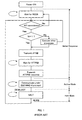
- FIG. 1 An initial response in communication between the non-contact type IC card and the reader/writer is standardized by ISO 14443-3.
- a processing flowchart of the non-contact type IC card is shown in Fig. 1.
- a protocol for communication between the non-contact type IC card and the reader/writer after initial response is also standardized by ISO 14443-4.
- the initial response is started by the fact that the power supply of the non-contact type IC card is turned on by the energy from the reader/writer and a REQB command is sent from the reader/writer to the IC card.
- the REQB command is to request the non-contact type IC card to make preparation and contains an application field identifier (AFI), an attribute information parameter (PARM) and a circuit redundancy check code (CRC).
- AFI application field identifier
- PARM attribute information parameter
- CRC circuit redundancy check code
- the ATQB response is a request response signal to the REQB command and contains information such as a pseudo unique identifier (PUPI), application information (application data), protocol information and a circuit redundancy check code (CRC).
- PUPI pseudo unique identifier
- application information application data
- protocol information protocol information
- CRC circuit redundancy check code
- the non-contact type IC card returns the ATQB response, receives an ATTRIB command and returns an ATTRIB response, then the initial response is completed and the non-contact type IC card proceeds to an active mode.
- the reader/writer transmits a command to the non-contact type IC card using the protocol described above.
- the non-contact type IC card executes the process corresponding to the received command and transmits the result of executing the command to the reader/writer.
- the non-contact type IC card upon receipt of a DESELECT command by the S block from the reader/writer, proceeds to the halt mode. As long as the non-contact type IC card is in halt mode, only the WUPB command can be received from the reader/writer.
- the WUPB command permits the non-contact type IC card to perform the operation from and including the detection of AFI coincidence again of all the initial response operations.
- the protocol information contained in the ATQB response to the REQB command at the time of initial response includes the parameters required by the non-contact type IC card for communication such as the bit transmission rate and the maximum frame size, which in turn includes the parameter FWI used by the reader/writer to set the frame waiting time.
- the reader/writer after receipt of FWI, executes the calculation of the following expression (2) and sets the frame waiting time FWT.
- FWT (256 x 16/fc) ⁇ 2 FWI
- fc is the carrier frequency generated by the reader/writer and standardized as 13.56 MHz.
- FWI is assigned the value of 0 to 14 (corresponding to FWT of about 302 ⁇ s to about 4949 ms).
- the specific value of FWI to be employed is determined by the non-contact type IC card. Therefore, the non-contact type IC card is required to complete the internal process thereof within the time corresponding to the FWI transmitted to the reader/writer. In the case where the non-contact type IC card fails to complete the internal process within the particular time, the reader/writer is permitted to handle the process as a time-out error.
- the non-contact type IC card fails to complete the process within the frame waiting time of the reader/writer.
- the non-contact type IC card is required to request the reader/writer to extend the frame waiting time and extend the time-out error determination time of the reader/writer.
- the communication command between the reader/writer and the non-contact type IC card for extension of the frame waiting time is specified by the protocol standard of ISO 14443-4.
- the long internal process required of the non-contact type IC card includes the arithmetic for various encryption/decryption requiring the coprocessor arithmetic.
- the FWI for the initial response is desirably set to as small a value as possible taking the overall performance of the IC card system into consideration.
- the coprocessor arithmetic may require the arithmetic time longer than the frame waiting time of the reader/writer.
- a method might be conceived in which communication is established between the reader/writer and the non-contact type IC card for extending the frame waiting time utilizing the timer interrupt or the like during the coprocessor arithmetic.
- the request (communication) issued for extending the frame waiting time during the arithmetic of the coprocessor adds the communication process to the original arithmetic process and increases the power consumption.
- the communication distance of the non-contact type IC card is shortened or the communication stability is reduced. Therefore, it is difficult to improve the efficiency by this method.
- the processing time of the coprocessor arithmetic varies with the type of arithmetic executed by the arithmetic coprocessor and the parameter applied to the arithmetic coprocessor.
- a plurality of cryptographic processes or a plurality of parameter processes even for a single cryptographic process are required, and it is difficult to predict the need to extend the frame waiting time by tabling the processing time in advance.
- the communication is carried out to extend the frame waiting time and the extension of the frame waiting time is set in the reader/writer before executing all the coprocessor arithmetic. Setting the frame waiting time in the reader/writer is a temporary process, and the frame waiting time of the reader/writer is restored to the initial value upon completion of one command process of the non-contact type IC card (upon transmission of the response to the command to the reader/writer).
- FIG. 2 An example of the conventional method of setting the frame waiting time is shown in Fig. 2.
- the reader/writer and the non-contact type IC card operate as described below in accordance with the ISO 14443-4 protocol.
- R/W designates the reader/writer and ICC the non-contact type IC card.
- the conventional method of setting the frame waiting time described above has at least two problems. Firstly, the communication to extend the frame waiting time even for the coprocessor arithmetic not requiring the extension of the frame waiting time (short in processing time) is carried out. Therefore, the waste of time is caused by the additional transmitting and receiving operation, thereby deteriorating the efficiency of communication between the reader/writer and the non-contact type IC card. Secondly, the communication required for frame waiting time extension before the coprocessor arithmetic undesirably provides a trigger to notify the offender of the analysis points such as key information on the encrypting and decrypting operation, often leading to a security problem.
- the present invention has been developed to obviate the aforementioned problems, and the object thereof is to provide an IC card capable of high-efficiency communication with small power consumption and a control method which mainly obviates the problem of power supplied to the non-contact type IC card, the communication problem and the problem of setting the frame waiting time.
- an IC card with a built-in coprocessor for an auxiliary arithmetic in addition to a main arithmetic processing unit comprising an interval timer for outputting an interrupt request signal upon lapse of a set time shorter than a frame waiting time; and coprocessor control means for controlling the operation of the coprocessor by suspending the supply of an operation clock to the coprocessor in accordance with an output of the interrupt request signal, and resuming the supply of the operation clock in accordance with a predetermined response input from an external device.
- the arithmetic process of the coprocessor exceeds a set time shorter than the frame waiting time. Then, the arithmetic process of the coprocessor is suspended, and a request for changing the communication conditions (for example, a frame waiting time extension request) is sent to an external device such as a reader/writer to change the communication conditions of the external device. Upon receipt of the input of a response confirming the change, the suspended arithmetic process of the coprocessor can be resumed. As a result, the power supply problem of the non-contact type IC card and the communication problem are avoided which otherwise might be caused by the simultaneous execution of the arithmetic process of the coprocessor operation and the communication with the external device.
- a request for changing the communication conditions for example, a frame waiting time extension request
- a frame waiting time extension request can be issued to the external device during the arithmetic process of the coprocessor, and an undue occurrence of a time-out error is avoided. Also, in the case where the arithmetic process of the coprocessor is completed before the lapse of the set time, the wasteful request for changing the communication conditions to the external device is saved for an improved communication and processing efficiency. Further, in view of the fact that the request for changing the communication conditions is issued to the external device upon the lapse of the set time after starting the arithmetic process of the coprocessor, security is improved against the offender attempting to use the communication as a trigger.
- an IC card in the first aspect of the present invention preferably further comprising interval timer setting means for determining, upon receipt of a command from the external device, the contents of the command and setting the set time shorter than the frame waiting time in the interval timer thereby to start the interval timer.
- the process of the interval timer setting means is preferably executed by the arithmetic processing unit.
- the set time in the interval timer can be adjusted in accordance with the contents of the command received from the external device, and therefore the communication efficiency and the processing efficiency are effectively improved.
- an IC card in any of the aspects described above, wherein the coprocessor control means preferably includes a control flag for controlling the suspension and resumption of the supply of the operation clock to the coprocessor; operation clock control means for controlling the suspension and resumption of the supply of the operation clock to the coprocessor in accordance with the state of the control flag; and control flag setting means for setting the control flag to the suspension mode upon receipt of the output of the interrupt request signal and setting the control flag to the resumption mode upon receipt of the response input.
- the process of the control flag setting means is preferably executed by the arithmetic processing unit.
- This third aspect of the present invention specifically implements the coprocessor control means and produces the operational effects of the IC card according to the first or second aspect of the present invention.
- an IC card in the third aspect described above wherein the arithmetic processing unit outputs a frame waiting time extension request to the external device upon suspension of the supply of the operation clock to the coprocessor, and sets the control flag to the resumption mode upon receipt of the response input from the external device.
- the process of the control flag setting means is executed by the arithmetic processing unit.
- communication is carried out with the external device to issue the frame waiting time extension request during the suspension of the arithmetic process of the coprocessor. Therefore, the frame waiting time can be extended while avoiding the shortage of power supply, thereby producing the operational effects of the IC card according to the first or second aspect of the present invention described above.
- an IC card in any of the aspects described above further comprising a nonvolatile memory for storing a program for normal processing, and a second memory lower in power consumption than the nonvolatile memory, wherein the program executed by the coprocessor is stored in the second memory at least when the coprocessor is in operation. Further, the access to the nonvolatile memory is preferably prohibited during the operation of the coprocessor. In this fifth aspect of the present invention, the power consumed for the arithmetic process of the coprocessor is reduced, and especially, the power supply problem of the non-contact type IC card is more effectively obviated.
- the IC card according to any of the aspects described above further comprises at least one of a non-contact interface and a contact interface for communication with the external device.
- the operational effects of the IC card according to each aspect of the present invention described above can be produced without regard to whether the communication interface is of contact or non-contact type.
- a control method of an IC card with a built-in coprocessor for an auxiliary operation in addition to a main arithmetic processing unit comprising: setting an interrupt permission so as to output an interrupt request signal upon lapse of a set time shorter than a frame waiting time; starting the arithmetic of the coprocessor after setting the interrupt permission; branching the operation to an interrupt process in response to the output of the interrupt request signal during the arithmetic of the coprocessor; and suspending the supply of an operation clock to the coprocessor and resuming the supply of the operation clock to the coprocessor upon receipt of a predetermined response input from the external device in the interrupt process.
- the control method preferably further comprises: determining upon receipt of a command from the external device, whether the command is an execution command of the coprocessor, and setting the interrupt permission when the command is an execution command of the coprocessor. Further, the control method preferably comprises: in the interrupt process, outputting a frame waiting time extension request to the external device after suspending the supply of the operation clock to the coprocessor, and resuming the supply of the operation clock upon receipt of a response input from the external device.
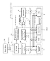
- the hardware configuration of the IC card according to the present invention is explained with reference to the system configuration shown in Fig. 3.
- the first embodiment assumes a non-contact type IC card.
- a non-contact type IC card 17 comprises a CPU 5 constituting a main arithmetic processing unit and a built-in coprocessor 3 for the auxiliary operation such as the cryptographic operation in addition to the CPU 5.
- the non-contact type IC card 17 further comprises an operation clock control flag 1 for suspending and resuming the supply of the coprocessor operation clock to the coprocessor 3, an operation clock control circuit 2 for controlling the operation of suspending and resuming the supply of the operation clock to the coprocessor 3, and an interval timer 4.
- the non-contact type IC card 17 also comprises an antenna 15 for transmitting/receiving the signal generated from a reader/writer 14 constituting an external device, an RF circuit 13 connected to the antenna 15, a communication interface 9 connected to the RF circuit 13, and an operation clock generating circuit 10 connected to the RF circuit 13. Furthermore, the non-contact type IC card 17 comprises a nonvolatile memory 12 such as a flash memory and a RAM 11 such as a static RAM for storing the control program to control the IC card having the above-mentioned configuration through the process executed by the CPU 5.
- a nonvolatile memory 12 such as a flash memory
- a RAM 11 such as a static RAM for storing the control program to control the IC card having the above-mentioned configuration through the process executed by the CPU 5.
- the RF circuit 13 demodulates the signal received from the reader/writer 14 and transmits the data to the communication interface 9.
- the RF circuit 13 also transmits the data from the communication interface 9 to the reader/writer 14 through the antenna 15. Further, the RF circuit 13 extracts the clock from the signal received from the reader/writer 14 and supplies the clock to the operation clock generating circuit 10.
- the operation clock 16 for activating various circuits in the non-contact type IC card 17 is generated and supplied to the operation clock control circuit 2, the CPU 5, the interval timer 4, the communication interface 9 and the like.
- the operation clock control flag 1, the coprocessor 3, the interval timer 4, the CPU 5, the communication interface 9, the nonvolatile memory 12 and the RAM 11 are connected to each other through a data bus 6.
- the control signals 7 output from the CPU 5 are input to the operation clock control flag 1, the coprocessor 3, the interval timer 4, the communication interface 9, the nonvolatile memory 12 and the RAM 11.
- the control signals 7 include, for example, an address signal, a readout signal and a write signal and the like.
- the interrupt request signal 8 output from the interval timer 4 is input to the CPU 5.
- the operations of the operation clock control flag 1, the coprocessor 3, the interval timer 4, the communication interface 9, the nonvolatile memory 12 and the RAM 11 can be controlled by the CPU 5 by executing the control program using the data bus 6 and the control signals 7.
- the CPU 5 can cause the interval timer 4 to perform an arbitrary counting operation by writing an arbitrary data to the interval timer 4 using the control signals 7 including an arbitrary address signal and a write signal through the data bus 6.
- the interval timer 4 started by the CPU 5 outputs the interrupt request signal 8 to the CPU 5 upon lapse of a designated set time, and the CPU 5 executes the interrupt process and recognizes the lapse of the frame waiting time by receiving the interrupt request signal 8.
- the program for the interrupt process is stored in the nonvolatile memory 12 or the RAM 11. This interrupt process includes the process of transmitting and receiving the frame waiting time extension signal to and from the reader/writer 14 using the communication interface 9.
- the CPU 5 can write the data "0" or "1" in the operation clock control flag 1 through the data bus 6 by the control signals 7 including an arbitrary address signal and a write signal.
- the CPU 5 also can read out the contents of the operation clock control flag 1 through the data bus 6 by the control signals 7 including an arbitrary address signal and a read signal.
- the CPU 5 can cause the coprocessor 3 to perform an arbitrary arithmetic by writing an arbitrary data to coprocessor 3 by the control signals 7 including an arbitrary address signal and a write signal through the data bus 6.
- the coprocessor 3 can be operated only when the operation clock 16 is supplied from the operation clock generating circuit 10, and suspends the arithmetic process while the operation clock 16 is not supplied from the operation clock generating circuit 10.
- the operation clock 16 generated by the operation clock generating circuit 10 and the state of the operation clock control flag 1 are input to the operation clock control circuit 2 for controlling the suspension and resumption of the supply of the operation clock of the coprocessor 3.
- the operation clock control circuit 2 is configured of, for example, an OR circuit to control whether the operation clock is supplied or not to the coprocessor 3. In the case where the data on the operation clock control flag 1 is "0", the operation clock control circuit 2 supplies the operation clock 16 supplied from the operation clock generating circuit 10 to the coprocessor 3. In the case where the data on the operation clock control flag 1 is "1", on the other hand, the operation clock control circuit 2 doesn't supply the operation clock 16 supplied from the operation clock generating circuit 10 to the coprocessor 3.
- the hardware configuration described above includes coprocessor control means for controlling the operation of the coprocessor 3 in such a manner that the supply of the operation clock to the coprocessor 3 is suspended in response to the output of the interrupt request signal 8 from the interval timer 4 and resumed in response to a predetermined response input from the external device, by the operation clock control flag 1, the operation clock control circuit 2 and the CPU 5 for setting data "0" or "1" in the operation clock control flag 1.
- the CPU 5 can control the suspension and resumption of the operation of the coprocessor 3 by controlling the operation clock control flag 1.
- the control means for frame waiting time extension is stored in the nonvolatile memory 12 as a control program executed by the CPU 5.
- the control means is processed in software fashion using the peripheral hardware by the CPU 5.
- Fig. 4 shows an example of the operation performed in the case where the S-WTX request is transmitted and received due to the overflow of the interval timer 4 used as a frame waiting time extension timer during the command execution (arithmetic process of the coprocessor 3) of the non-contact type IC card 17.
- the following processes (1) to (9) are executed.
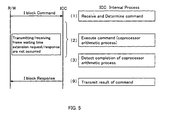
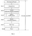
- Fig. 5 shows an example of the operation performed in the case where the S-WTX request is not transmitted nor received due to the lack of overflow of the interval timer 4 used as a frame waiting time extension timer during the command execution (arithmetic process of the coprocessor 3) of the non-contact type IC card 17.
- the following processes (1) to (3) and (9) are executed.
- This embodiment is so configured that the operation of the coprocessor 3 and the communication between the reader/writer 14 and the non-contact type IC card 17 are not performed at the same time.
- the reader/writer 14 transmits an arbitrary command to the IC card by the I block.
- the CPU 5 built in the non-contact type IC card 17 receives the command and determines the contents thereof.
- Process (2) The CPU 5 executes the command (arithmetic process of the coprocessor).
- Process (3) The CPU 5 monitors the end of the arithmetic process of the coprocessor 3 and upon detection of the end of the arithmetic process, executes the following process (9).
- Process (4) In the case where the frame waiting time extension interval timer 4 overflows before detection of the end of the arithmetic process during the process (3), the interrupt request signal 8 is generated so that the process branches to the interrupt start routine of the non-contact type IC card 17, and the processes (5) to (8) are executed.
- Process (5) The CPU 5 sets the data "1" in the operation clock control flag 1 and causes the operation clock control circuit 2 to suspend the supply of the operation clock 16 to the coprocessor 3. As a result, the operation of the coprocessor 3 is suspended.
- the CPU 5 calls the S-WTX request transmitting/receiving process. In the process, the CPU 5 transmits the frame waiting time extension request (S-WTX request) to the reader/writer 14.
- the S-WTX request is to request the extension of the frame waiting time by the command of the S block (control block under ISO 14443-4 protocol).
- the reader/writer 14 extends the time-out time in accordance with the S-WTX request.
- the reader/writer 14 transmits the frame waiting time extension response (S-WTX response) to the non-contact type IC card 17.
- S-WTX response is given from the reader/writer 14 by the S-block command as a response to the S-WTX request.
- Process (8) The CPU 5 sets the data "0" in the operation clock control flag 1, and causes the operation clock control circuit 2 to resume the supply of the operation clock 16 to the coprocessor 3. As a result, the operation of the coprocessor 3 is resumed.
- the non-contact type IC card 17 returns from the interrupt to the process (3).
- the CPU 5 upon complete execution of the command, transmits the command execution result to the reader/writer 14 by the I block (information block under ISO 14443-4 protocol).
- the control processes described above start the interrupt process by the CPU 5 only in the case where the interrupt request signal 8 is generated by the interval timer 4 during the arithmetic process of the coprocessor 3.
- the operation (arithmetic process) of the coprocessor 3 is temporarily suspended, and after extending the frame waiting time for the reader/writer 14, the operation of the coprocessor 3 can be resumed.
- the frame waiting time can be transmitted and received advantageously in terms of security without being noticed as a trigger by an offender to know the analysis points.
- the command can be completely processed before generation of the communication for frame waiting time extension, and therefore the communication efficiency can improved.
- the first embodiment described above represents a case in which the communication between the reader/writer 14 and the non-contact type IC card 17 is not conducted simultaneously with the operation of the coprocessor 3.
- the first embodiment also illustrates a case in which the program executed by the coprocessor 3 is stored in the nonvolatile memory 12.
- the operation of the coprocessor 3 can be performed with lower power consumption on the RAM 11 rather than on the nonvolatile memory 12.
- the power consumption in the operation of the coprocessor 3 can be reduced therefore, by performing interrupt operation on the RAM 11 until the operation of the coprocessor 3 is suspended while prohibiting the access to the nonvolatile memory 12.
- the power consumption can be reduced by executing the program for the communication between the reader/writer 14 and the non-contact type IC card 17 at the time of frame waiting time extension on the RAM 11.
- the coprocessor processing program and the communication processing program between the reader/writer 14 and the non-contact type IC card 17 occurred at the time of frame waiting time extension are executed on the RAM 11, and the access to the nonvolatile memory 12 is prohibited during the execution of the coprocessor processing program.
- This embodiment is specifically explained with reference to the hardware configuration shown in Fig. 3 and the flowcharts shown in Figs. 6 to 10.
- the hardware configuration of the non-contact type IC card 17 is assumed to be the same as that according to the first embodiment.
- the control means of the non-contact type IC card 17 is stored in the nonvolatile memory 12 as a control program executed by the CPU 5.
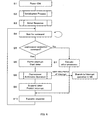
- step S1 power begins to be supplied to the non-contact type IC card 17 by the radio wave from the reader/writer 14. Then, the operation of the non-contact type IC card 17 starts (step S1).
- step S2 executes the initialization process (step S2).
- the initialization process of step S2 is configured, as shown in Fig. 7, as an initialization process subroutine, for example.
- the program for each of the data transmitting/receiving process (step S21), the interrupt process (step S22) and the coprocessor arithmetic process (step S23) is transferred from the nonvolatile memory 12 to the RAM 11.
- step S3 the initial response operation shown in Fig. 1 is carried out between the non-contact type IC card 17 and the reader/writer 14, so that the non-contact type IC card 17 comes in a state (active state) communicable under ISO 14443-4 protocol.
- the non-contact type IC card 17 branches, in step S4, to the process of receiving the data transferred to the RAM 11 in step S2 and waits for a command (I-block command) transmitted from the reader/writer 14.
- the non-contact type IC card 17 upon receipt of the command (I-block command) from the reader/writer 14 in step S4, proceeds to step S5 and determines whether the command requires the execution of the coprocessor 3 or not. In the case where it is determined that the received command requires the execution of the coprocessor 3, the non-contact type IC card 17 proceeds to step S6. In step S6, the count value for generating the timer interrupt before lapse of the frame waiting time is set in the interval timer 4, and then the timer interrupt is permitted thereby to start the interval timer 4. In the case where it is determined that the received command requires no execution of the coprocessor 3, on the other hand, the non-contact type IC card 17 proceeds to step S7 where other processes are executed.
- step S6 After starting the interval timer 4 in step S6, the non-contact type IC card 17 branches to the coprocessor arithmetic operation (step S8) stored in the RAM 11 in step S2.
- the non-contact type IC card 17 After branching to step S8, as shown in Fig. 8, the non-contact type IC card 17 starts the coprocessor arithmetic from inside the RAM 11 (step S81), and waits for the end of the arithmetic process of the coprocessor 3 in step S82. In the case where the interval timer 4 overflows in step S82, the interrupt request signal 8 is generated to start the interrupt process. Once the interrupt process starts, the non-contact type IC card 17 branches to the interrupt process of step S8 stored in the RAM 11 in step S2.
- the non-contact type IC card 17 completes the arithmetic process of the coprocessor 3 in step S8.
- the non-contact type IC card 17 suspends the operation of the interval timer 4 in step SInt1.
- the non-contact type IC card 17 sets the data "1" in the operation clock control flag 1 and causes the operation clock control circuit 2 to suspend the supply of the operation clock 16 to the coprocessor 3.
- the non-contact type IC card 17 transmits the S-WTX request to the reader/writer 14 in step SInt31 as shown in Fig. 10.
- step SInt32 the non-contact type IC card 17 waits for the transmission of the S-WTX response from the reader/writer 14. At the same time, the reader/writer 14 extends the time-out point of the frame waiting time. Upon receipt of the S-WTX response from the reader/writer 14, the non-contact type IC card 17 proceeds to step SInt4.
- step SInt4 the non-contact type IC card 17 sets the data "0" in the operation clock control flag 1, and the operation clock control circuit 2 resumes the supply of the operation clock 16 to the coprocessor 3. As a result, the operation of the coprocessor 3 is resumed.
- step SInt5 the operation of the interval timer 4 is resumed thereby to end the interrupt process.
- the non-contact type IC card 17 again returns to step S82 (Fig. 8), and waits for the end of the arithmetic process of the coprocessor 3.
- the processor operation in step S8 is completed, and the non-contact type IC card 17 stops the operation of the interval timer 4 and prohibits the timer interrupt in step S9.
- step S10 the non-contact type IC card 17 transmits the command execution result to the reader/writer 14 by I block in step S10.
- the process of step S10 is executed by branching to the data transmission process transferred to the RAM 11 in step S2.
- the non-contact type IC card 17 is controlled in such a manner that the operation of the coprocessor 3 and the communication between the reader/writer 14 and the non-contact type IC card 17 are prevented from being simultaneously carried out, and the coprocessor processing program is executed on the RAM 11 while prohibiting the access to the nonvolatile memory 12.
- the non-contact type IC card having a non-contact interface is explained in the embodiments above.
- the control process and the control means according to the present invention are also applicable to a contact type IC card having a contact interface with equal effect.
- the IC card operates according to the initial response process of the contact type IC card shown in Fig. 11 in the initial response routine in step S3 in the flowchart shown in Fig. 6.
- step S3 the operation at and subsequent to step S3 is similar to that of the non-contact type IC card having a non-contact interface.
Landscapes
- Engineering & Computer Science (AREA)
- Theoretical Computer Science (AREA)
- Physics & Mathematics (AREA)
- Computer Hardware Design (AREA)
- General Physics & Mathematics (AREA)
- Microelectronics & Electronic Packaging (AREA)
- Electromagnetism (AREA)
- General Engineering & Computer Science (AREA)
- Life Sciences & Earth Sciences (AREA)
- Biotechnology (AREA)
- Computer Networks & Wireless Communication (AREA)
- Chemical & Material Sciences (AREA)
- Chemical Kinetics & Catalysis (AREA)
- Hydrology & Water Resources (AREA)
- Environmental & Geological Engineering (AREA)
- Water Supply & Treatment (AREA)
- Organic Chemistry (AREA)
- Credit Cards Or The Like (AREA)
- Storage Device Security (AREA)
- Power Sources (AREA)
- Executing Machine-Instructions (AREA)
Applications Claiming Priority (2)
| Application Number | Priority Date | Filing Date | Title |
|---|---|---|---|
| JP2004027573A JP4072503B2 (ja) | 2004-02-04 | 2004-02-04 | 補助演算用コプロセッサ内蔵型icカード及びその制御方法 |
| JP2004027573 | 2004-02-04 |
Publications (1)
| Publication Number | Publication Date |
|---|---|
| EP1564630A1 true EP1564630A1 (de) | 2005-08-17 |
Family
ID=34697857
Family Applications (1)
| Application Number | Title | Priority Date | Filing Date |
|---|---|---|---|
| EP05250585A Withdrawn EP1564630A1 (de) | 2004-02-04 | 2005-02-03 | Chipkarte mit eingebautem arithmetischem Coprozessor und Steuerungsverfahren dafür |
Country Status (7)
| Country | Link |
|---|---|
| US (1) | US7364083B2 (de) |
| EP (1) | EP1564630A1 (de) |
| JP (1) | JP4072503B2 (de) |
| KR (1) | KR100705522B1 (de) |
| CN (1) | CN100465991C (de) |
| SG (1) | SG113612A1 (de) |
| TW (1) | TWI307862B (de) |
Cited By (3)
| Publication number | Priority date | Publication date | Assignee | Title |
|---|---|---|---|---|
| WO2009112963A2 (en) | 2008-03-11 | 2009-09-17 | Nxp B.V. | Integrated circuit card |
| EP3757891A1 (de) * | 2019-06-25 | 2020-12-30 | Gemalto Sa | Steuerungsverfahren und -system eines peripheriegeräts für ein system mit funkfrequenzcontroller |
| EP3757892A1 (de) * | 2019-06-26 | 2020-12-30 | Gemalto Sa | Funkfrequenzkommunikationsverfahren zwischen einem lesegerät und einer mit einem peripheriegerät verbundenen vorrichtung mit messung des funkfrequenzfelds |
Families Citing this family (19)
| Publication number | Priority date | Publication date | Assignee | Title |
|---|---|---|---|---|
| JP4072503B2 (ja) * | 2004-02-04 | 2008-04-09 | シャープ株式会社 | 補助演算用コプロセッサ内蔵型icカード及びその制御方法 |
| JP4239988B2 (ja) * | 2005-03-07 | 2009-03-18 | ソニー株式会社 | 通信システム、通信装置、有線通信装置、および通信方法 |
| JP4842017B2 (ja) * | 2005-05-30 | 2011-12-21 | 株式会社半導体エネルギー研究所 | 半導体装置 |
| KR101219069B1 (ko) * | 2005-05-30 | 2013-01-18 | 가부시키가이샤 한도오따이 에네루기 켄큐쇼 | 반도체 장치 및 그것의 구동 방법 |
| JP2007026095A (ja) * | 2005-07-15 | 2007-02-01 | Matsushita Electric Ind Co Ltd | 並列演算装置 |
| JP2007234001A (ja) * | 2006-01-31 | 2007-09-13 | Semiconductor Energy Lab Co Ltd | 半導体装置 |
| EP2033145B1 (de) * | 2006-06-15 | 2011-04-06 | Kabushiki Kaisha Toshiba | Tragbares elektronisches gerät und steuerverfahren dafür |
| JP5013966B2 (ja) * | 2007-05-24 | 2012-08-29 | 三菱電機株式会社 | 演算処理装置 |
| JP5295657B2 (ja) | 2008-06-27 | 2013-09-18 | ルネサスエレクトロニクス株式会社 | 半導体集積回路、半導体集積回路を実装したicカードおよびその動作方法 |
| JP4553041B2 (ja) * | 2008-08-05 | 2010-09-29 | ソニー株式会社 | 通信装置、リーダ/ライタ、通信システム、および通信方法 |
| JP5578811B2 (ja) | 2009-06-30 | 2014-08-27 | キヤノン株式会社 | 情報処理装置、情報処理装置の制御方法及びプログラム |
| JP5602075B2 (ja) * | 2011-03-17 | 2014-10-08 | 株式会社東芝 | 携帯可能電子装置、icカードよび携帯可能電子装置に用いられる通信方法 |
| DE102012219205A1 (de) * | 2012-10-22 | 2014-05-08 | Robert Bosch Gmbh | Vorrichtung und Verfahren zur Ausführung eines kryptographischen Verfahrens |
| DE102013105575A1 (de) * | 2013-05-30 | 2014-12-04 | Infineon Technologies Ag | Chipkartenmodul, Chipkarte, und Verfahren zum Herstellen eines Chipkartenmoduls |
| JP6316522B1 (ja) | 2017-01-25 | 2018-04-25 | 三菱電機株式会社 | 計算機装置、タスク起動方法およびタスク起動プログラム |
| US10664669B2 (en) | 2018-01-30 | 2020-05-26 | Idex Biometrics Asa | Device architecture |
| US10679020B2 (en) | 2018-01-30 | 2020-06-09 | Idex Biometrics Asa | Voltage regulation |
| FR3105629B1 (fr) * | 2019-12-19 | 2023-03-17 | St Microelectronics Rousset | Procédé de gestion d’alimentation |
| KR20210132862A (ko) * | 2020-04-28 | 2021-11-05 | 삼성전자주식회사 | 클록 제어 방법 및 이를 위한 전자 장치 |
Citations (5)
| Publication number | Priority date | Publication date | Assignee | Title |
|---|---|---|---|---|
| EP0446519A2 (de) * | 1990-03-13 | 1991-09-18 | Mitsubishi Denki Kabushiki Kaisha | Kontaktlose integrierte Schaltungskarte |
| US5666537A (en) * | 1994-08-12 | 1997-09-09 | Intel Corporation | Power down scheme for idle processor components |
| EP1134693A2 (de) * | 2000-03-15 | 2001-09-19 | Kabushiki Kaisha Toshiba | Vorrichtung für kontaktlose Kommunikation und Kontrollverfahren für derartige Vorrichtung |
| US20020166075A1 (en) * | 2001-05-04 | 2002-11-07 | Sanjay Agarwal | Low power interface between a control processor and a digital signal processing coprocessor |
| US20040015594A1 (en) * | 2000-02-03 | 2004-01-22 | Pascal Guterman | Time management at communication level for a smart card-type entity |
Family Cites Families (32)
| Publication number | Priority date | Publication date | Assignee | Title |
|---|---|---|---|---|
| DK174975B1 (da) * | 1988-05-06 | 2004-04-05 | Toppan Printing Co Ltd | Integreret kredsløbskort |
| JP2719416B2 (ja) * | 1989-08-31 | 1998-02-25 | キヤノン株式会社 | Icカード |
| JP2724008B2 (ja) * | 1989-12-01 | 1998-03-09 | 沖電気工業株式会社 | 本人確認処理システム及び本人確認処理方法 |
| JP3053301B2 (ja) * | 1992-09-11 | 2000-06-19 | 三菱電機株式会社 | 半導体集積回路及びicカード |
| WO1995025310A1 (en) * | 1994-03-14 | 1995-09-21 | Apple Computer, Inc. | A peripheral processor card for upgrading a computer |
| JPH0962808A (ja) * | 1995-08-25 | 1997-03-07 | Mitsubishi Electric Corp | 非接触icカード及び非接触icカードシステム |
| CN1114160C (zh) * | 1996-03-06 | 2003-07-09 | 松下电工株式会社 | 可编程序控制器 |
| FR2758195B1 (fr) * | 1997-01-09 | 1999-02-26 | Sgs Thomson Microelectronics | Coprocesseur d'arithmetique modulaire comprenant deux circuits de multiplication operant en parallele |
| US6488211B1 (en) * | 1997-05-15 | 2002-12-03 | Mondex International Limited | System and method for flexibly loading in IC card |
| US6192442B1 (en) * | 1998-04-29 | 2001-02-20 | Intel Corporation | Interrupt controller |
| US6460146B1 (en) * | 1998-12-04 | 2002-10-01 | Cisco Technology, Inc. | System and method for establishing processor redundancy |
| EP1030266B1 (de) * | 1999-02-19 | 2009-05-06 | Nippon Telegraph and Telephone Corporation | Kontaktlose Chipkarte und System hierfür |
| JP2001136100A (ja) * | 1999-11-04 | 2001-05-18 | Matsushita Electronics Industry Corp | 情報通信処理方式 |
| DE10000503A1 (de) * | 2000-01-08 | 2001-07-12 | Philips Corp Intellectual Pty | Datenverarbeitungseinrichtung und Verfahren zu dessen Betrieb |
| TW536672B (en) * | 2000-01-12 | 2003-06-11 | Hitachi Ltd | IC card and microcomputer |
| JP4261802B2 (ja) * | 2000-04-28 | 2009-04-30 | 株式会社ルネサステクノロジ | Icカード |
| IL138323A0 (en) * | 2000-09-07 | 2009-02-11 | Av Doron | Smart magnetic card |
| US7069287B2 (en) * | 2000-09-19 | 2006-06-27 | Worcester Polytechnic Institute | Method for efficient computation of odd characteristic extension fields |
| EP1327045A1 (de) * | 2000-10-20 | 2003-07-16 | Blue Soltech Co., Ltd. | Funkfernsteuerung zur öffnung und schliessung von türen und zur bedienung von haushaltsgeräten |
| DE10061998A1 (de) * | 2000-12-13 | 2002-07-18 | Infineon Technologies Ag | Kryptographieprozessor |
| JP2002222402A (ja) * | 2001-01-24 | 2002-08-09 | Dainippon Printing Co Ltd | Icカード |
| JP2002288616A (ja) * | 2001-03-28 | 2002-10-04 | Omron Corp | 非接触媒体 |
| DE10127424B4 (de) * | 2001-06-06 | 2004-09-02 | Infineon Technologies Ag | Elektronische Schaltung mit asynchroner Taktung von Peripherieeinheiten |
| JP3865629B2 (ja) * | 2001-07-09 | 2007-01-10 | 株式会社ルネサステクノロジ | 記憶装置 |
| JP3863011B2 (ja) * | 2001-11-29 | 2006-12-27 | シャープ株式会社 | コンビネーション型icカード、及びその制御方法、並びにそのシステムプログラム |
| JP2004104539A (ja) * | 2002-09-11 | 2004-04-02 | Renesas Technology Corp | メモリカード |
| JP3929888B2 (ja) * | 2002-12-25 | 2007-06-13 | 株式会社東芝 | Icカード |
| US7478260B2 (en) * | 2003-10-20 | 2009-01-13 | Hewlett-Packard Development Company, L.P. | System and method for setting a clock rate in a memory card |
| JP2007041629A (ja) * | 2003-11-04 | 2007-02-15 | Renesas Technology Corp | メモリカード及び半導体装置 |
| JP2005242989A (ja) * | 2004-01-28 | 2005-09-08 | Toshiba Microelectronics Corp | 非接触icカードのリーダライタ端末装置、通信システム及び非接触データキャリア |
| JP4072503B2 (ja) * | 2004-02-04 | 2008-04-09 | シャープ株式会社 | 補助演算用コプロセッサ内蔵型icカード及びその制御方法 |
| JP4351987B2 (ja) * | 2004-11-19 | 2009-10-28 | 株式会社東芝 | モンゴメリ変換装置、演算装置、icカード、暗号装置、復号装置及びプログラム |
-
2004
- 2004-02-04 JP JP2004027573A patent/JP4072503B2/ja not_active Expired - Fee Related
-
2005
- 2005-02-03 US US11/048,867 patent/US7364083B2/en not_active Expired - Fee Related
- 2005-02-03 EP EP05250585A patent/EP1564630A1/de not_active Withdrawn
- 2005-02-03 SG SG200500635A patent/SG113612A1/en unknown
- 2005-02-03 KR KR1020050009918A patent/KR100705522B1/ko not_active Expired - Fee Related
- 2005-02-04 TW TW094103713A patent/TWI307862B/zh not_active IP Right Cessation
- 2005-02-04 CN CNB2005100079669A patent/CN100465991C/zh not_active Expired - Fee Related
Patent Citations (5)
| Publication number | Priority date | Publication date | Assignee | Title |
|---|---|---|---|---|
| EP0446519A2 (de) * | 1990-03-13 | 1991-09-18 | Mitsubishi Denki Kabushiki Kaisha | Kontaktlose integrierte Schaltungskarte |
| US5666537A (en) * | 1994-08-12 | 1997-09-09 | Intel Corporation | Power down scheme for idle processor components |
| US20040015594A1 (en) * | 2000-02-03 | 2004-01-22 | Pascal Guterman | Time management at communication level for a smart card-type entity |
| EP1134693A2 (de) * | 2000-03-15 | 2001-09-19 | Kabushiki Kaisha Toshiba | Vorrichtung für kontaktlose Kommunikation und Kontrollverfahren für derartige Vorrichtung |
| US20020166075A1 (en) * | 2001-05-04 | 2002-11-07 | Sanjay Agarwal | Low power interface between a control processor and a digital signal processing coprocessor |
Cited By (9)
| Publication number | Priority date | Publication date | Assignee | Title |
|---|---|---|---|---|
| WO2009112963A2 (en) | 2008-03-11 | 2009-09-17 | Nxp B.V. | Integrated circuit card |
| WO2009112963A3 (en) * | 2008-03-11 | 2009-11-19 | Nxp B.V. | Integrated circuit card |
| US8172150B2 (en) | 2008-03-11 | 2012-05-08 | Nxp B.V. | Integrated circuit card |
| EP3757891A1 (de) * | 2019-06-25 | 2020-12-30 | Gemalto Sa | Steuerungsverfahren und -system eines peripheriegeräts für ein system mit funkfrequenzcontroller |
| WO2020260024A1 (fr) | 2019-06-25 | 2020-12-30 | Thales Dis France Sa | Procédé et système de pilotage de périphérique pour système à contrôleur radiofréquence |
| DE212020000669U1 (de) | 2019-06-25 | 2022-04-25 | Thales Dis France Sas | System zur Ansteuerung eines Peripheriegeräts für ein System mit einem Hochfrequenz-Controller |
| EP3757892A1 (de) * | 2019-06-26 | 2020-12-30 | Gemalto Sa | Funkfrequenzkommunikationsverfahren zwischen einem lesegerät und einer mit einem peripheriegerät verbundenen vorrichtung mit messung des funkfrequenzfelds |
| WO2020260316A1 (fr) | 2019-06-26 | 2020-12-30 | Thales Dis France Sa | Procede de communication radiofrequence entre un lecteur et un dispositif relie a un peripherique, avec mesure de champ radiofrequence |
| DE212020000663U1 (de) | 2019-06-26 | 2022-04-25 | Thales Dis France Sas | System zur Kommunikation zwischen einem Hochfrequenz-Lesegerät und einer Hochfrequenz-Transpondervorrichtung |
Also Published As
| Publication number | Publication date |
|---|---|
| TW200535707A (en) | 2005-11-01 |
| KR100705522B1 (ko) | 2007-04-10 |
| JP4072503B2 (ja) | 2008-04-09 |
| US20050167513A1 (en) | 2005-08-04 |
| TWI307862B (en) | 2009-03-21 |
| CN100465991C (zh) | 2009-03-04 |
| KR20060041632A (ko) | 2006-05-12 |
| JP2005222194A (ja) | 2005-08-18 |
| US7364083B2 (en) | 2008-04-29 |
| CN1652152A (zh) | 2005-08-10 |
| SG113612A1 (en) | 2005-08-29 |
Similar Documents
| Publication | Publication Date | Title |
|---|---|---|
| US7364083B2 (en) | IC card with built-in coprocessor for auxiliary arithmetic, and control method thereof | |
| JP3889158B2 (ja) | Ic搭載カード及びカードシステム | |
| US7789313B2 (en) | Fully simultaneous information on variations in status for an object with a dual interface | |
| US9214986B2 (en) | Non-volatile memory for NFC router | |
| JP2001283174A (ja) | Icカード、icチップ、データ保証方法および電源監視方法 | |
| JP3833939B2 (ja) | 複合icカード | |
| US9107238B2 (en) | Information processing device, information processing method, and program | |
| JP3929761B2 (ja) | 半導体装置の動作制御方法、半導体装置動作制御プログラム、半導体装置動作制御プログラムを記録した記録媒体、半導体装置、およびicカード | |
| US8897736B2 (en) | Mobile communication terminal device | |
| EP1793331A1 (de) | Halbleiter-speicherkarte | |
| US20080048042A1 (en) | Immunity to Variations in Limited Resources, Provided to an Object with a Dual Interface | |
| JPH1115934A (ja) | 無電池方式のrfid | |
| EP1272974B1 (de) | Datenträger mit einem chip und mittel zur einstellbaren spannungsversorgung einer weiteren datenträgerkomponente | |
| CN115665714B (zh) | 近场通信的方法和装置、主控设备、nfc芯片和nfc设备 | |
| CN109993261B (zh) | 一种智能卡、应用实现方法、装置及计算机可读存储介质 | |
| JP7424536B1 (ja) | 電子情報記憶媒体、icチップ、icカード、通信パラメータ送信方法、及びプログラム | |
| JP2002109494A (ja) | Icカード、リーダライタ、icカードシステム及びicカードの動作条件設定方法 | |
| EP2299414B1 (de) | Tragbare elektronische Vorrichtung, Steuerverfahren für die tragbare elektronische Vorrichtung und IC-Karte | |
| JP2005275456A (ja) | 携帯可能電子媒体、携帯可能電子媒体に用いられる集積回路、及び、携帯可能電子媒体の発行方法 | |
| EP1649712A1 (de) | Schaltung für einen datenträger, wobei die schaltung aus einem energiesparverarbeitungsmodus in einen normalverbrauchsverarbeitungsmodus umgeschaltet werden kann | |
| JP4669262B2 (ja) | Icカード用icチップ、icカード及びicカード用プログラム | |
| JP2006195901A (ja) | 半導体装置 | |
| JP5787692B2 (ja) | Icカード、携帯可能電子装置、及びicカードの制御方法 | |
| CN115840968A (zh) | 兼具逻辑加密卡和cpu卡的芯片及其通信方法 |
Legal Events
| Date | Code | Title | Description |
|---|---|---|---|
| PUAI | Public reference made under article 153(3) epc to a published international application that has entered the european phase |
Free format text: ORIGINAL CODE: 0009012 |
|
| AK | Designated contracting states |
Kind code of ref document: A1 Designated state(s): AT BE BG CH CY CZ DE DK EE ES FI FR GB GR HU IE IS IT LI LT LU MC NL PL PT RO SE SI SK TR |
|
| AX | Request for extension of the european patent |
Extension state: AL BA HR LV MK YU |
|
| 17P | Request for examination filed |
Effective date: 20051031 |
|
| AKX | Designation fees paid |
Designated state(s): DE FR GB |
|
| 17Q | First examination report despatched |
Effective date: 20060707 |
|
| STAA | Information on the status of an ep patent application or granted ep patent |
Free format text: STATUS: THE APPLICATION IS DEEMED TO BE WITHDRAWN |
|
| 18D | Application deemed to be withdrawn |
Effective date: 20081218 |