EP1564681A1 - Procédé pour la compensation de vignettage - Google Patents
Procédé pour la compensation de vignettage Download PDFInfo
- Publication number
- EP1564681A1 EP1564681A1 EP04392001A EP04392001A EP1564681A1 EP 1564681 A1 EP1564681 A1 EP 1564681A1 EP 04392001 A EP04392001 A EP 04392001A EP 04392001 A EP04392001 A EP 04392001A EP 1564681 A1 EP1564681 A1 EP 1564681A1
- Authority
- EP
- European Patent Office
- Prior art keywords
- pixel
- sensor array
- center
- lens
- correction factor
- Prior art date
- Legal status (The legal status is an assumption and is not a legal conclusion. Google has not performed a legal analysis and makes no representation as to the accuracy of the status listed.)
- Withdrawn
Links
Images


Classifications
-
- G—PHYSICS
- G06—COMPUTING OR CALCULATING; COUNTING
- G06T—IMAGE DATA PROCESSING OR GENERATION, IN GENERAL
- G06T5/00—Image enhancement or restoration
- G06T5/90—Dynamic range modification of images or parts thereof
- G06T5/94—Dynamic range modification of images or parts thereof based on local image properties, e.g. for local contrast enhancement
-
- H—ELECTRICITY
- H04—ELECTRIC COMMUNICATION TECHNIQUE
- H04N—PICTORIAL COMMUNICATION, e.g. TELEVISION
- H04N23/00—Cameras or camera modules comprising electronic image sensors; Control thereof
- H04N23/80—Camera processing pipelines; Components thereof
- H04N23/81—Camera processing pipelines; Components thereof for suppressing or minimising disturbance in the image signal generation
-
- H—ELECTRICITY
- H04—ELECTRIC COMMUNICATION TECHNIQUE
- H04N—PICTORIAL COMMUNICATION, e.g. TELEVISION
- H04N1/00—Scanning, transmission or reproduction of documents or the like, e.g. facsimile transmission; Details thereof
- H04N1/40—Picture signal circuits
- H04N1/401—Compensating positionally unequal response of the pick-up or reproducing head
-
- H—ELECTRICITY
- H04—ELECTRIC COMMUNICATION TECHNIQUE
- H04N—PICTORIAL COMMUNICATION, e.g. TELEVISION
- H04N25/00—Circuitry of solid-state image sensors [SSIS]; Control thereof
- H04N25/60—Noise processing, e.g. detecting, correcting, reducing or removing noise
- H04N25/61—Noise processing, e.g. detecting, correcting, reducing or removing noise the noise originating only from the lens unit, e.g. flare, shading, vignetting or "cos4"
Definitions
- This invention relates generally to image processing and relates more particularly to a method and an algorithm to compensate lens shading or vignetting in digital images.
- Photographically, vignetting means the darkening of the corners relative to the centre of an image. All camera lenses suffer, more or less, of these optical phenomena.
- Fig. 1 prior art describes some major steps performed in image processing.
- a raw image is obtained.
- the offset/gain calibration is performed, followed by the compensation for vignetting 12.
- the last step 13 is the color processing.
- a simple lens obeys an optical law called the "cos-4 th law" (cosine of the angle of incidence off the lens axis to the 4 th power.
- the cos-4 th influence comes from a number of factors, including that the light gets spread out over a larger area, and that the corners of the image are further away from the center of the lens than the on-axis part of the image.
- Cos (10 degrees) is 0.9848, so to the 4 th power is 0.9406. Therefore the corners get 94 percent as much light as the center, a generally imperceptible difference.
- a 20-degree angle of view for a 35mm camera equates to a 123mm lens.
- cos4th comes to 0.39. So now the corners only get 39 percent of the light that the center gets.
- For a 20mm lens this goes down to 21 percent, and for a 15 mm lens this goes down to 10.5 percent. Obviously the last case is unworkable and is not acceptable.
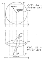
- FIG. 2a prior art shows a top view of a lens/sensor system comprising a lens 21 and a sensor 20.
- the center 22 of the lens 20, which is also the center of the sensor, has the coordinates X center , Y center .
- a pixel 23 of the sensor 20 has the coordinates x, y.
- Fig 2b prior art shows a side view of said lens/sensor system comprising said lens 21 and sensor 20. Light ray traces 25 emanating from an object 24 are reunited at the pixel 23 of the sensor.
- the US patent application, serial number 10/379,863 , filed on March 4, 2003 , and assigned to the same assignee as the present invention describes a different method to compensate lens shading or vignetting in digital cameras.
- the compensation for vignetting is done in two steps.
- the first step is done during production of the camera unit and involves taking and analyzing an image of a test screen, preferably a gray test screen. This results in a set of e.g. 5x5 coefficients describing a polynomial surface.
- the second step is done for each image that is taken by the camera and involves calculating and applying a gain-table based on polynomial coefficients to all pixels of the image to compensate vignetting.
- U. S. Patent (6,388,706 to Takizawa et al.) describes an image processing method for an electronic camera which includes a photoelectric element having plural sensors and color filters in plural different colors, wherein each of the plural sensors corresponds to a respective one of the color filters in the different colors.
- the method includes the steps of: obtaining a signal value from a target sensor; obtaining the first average value from signal values of the sensors; obtaining the second average value from signal values of the sensors and obtaining an interpolation value for a color, which is different from that of the color filter of the target sensor, of the target sensor according to the signal value from the target sensor, the first average value and the second average value.
- the vignetting of a lens causes a decrease in marginal brightness of an image field. However, if the correction for the decrease in marginal brightness is performed at the same time of performing white balance adjustment or/and gain adjustment, the correction for the marginal brightness may be performed upon decreasing the calculation volume.
- U. S. Patent (6,323,934 to Enomoto) discloses an image processing method in which at least one aberration of an optically recorded image selected from among lateral chromatic aberration, distortion, decrease on the brightness of the edge of image field and image blurring is corrected based on lens characteristics of a taking lens and position information of the image.
- an image processing apparatus comprises an acquiring section for acquiring information identifying a taking lens; a storage section for storing lens characteristics associated with the type of the taking lens; and a correction section which receives the corresponding lens characteristics of the taking lens from the storage section and corrects at least one aberration selected from among lateral chromatic aberration, distortion, vignetting and image blurring.
- High-quality images that are free from color mismatch, distortion, uneven brightness, blurring and other defects, or both vignetting and distortion can be outputted consistently.
- a principal object of the present invention is to achieve a fast and efficient way to calculate correction values to compensate vignetting in digital cameras.
- a method to compensate vignetting in digital cameras comprises a multiplication of each pixel output of the array sensor of the camera with a variable correction factor defined for each pixel, wherein said variable correction factor depends upon the distance between each pixel and the center of said sensor array.
- Said method comprises a multiplication of each pixel output of the array sensor of the camera, except pixels being close to the center, with a variable correction factor defined for said pixels, wherein said variable correction factor depends upon the distance between said pixels and the center of said sensor array.
- a method to compensate vignetting in digital cameras is using a correction factor for pixel output of its sensor array wherein the required computation comprises the following steps, first, to provide x, y coordinates for the pixels of the sensor array, to assign a first constant factor, describing the geometry of thelens/sensor system to a first variable f1, to assign a second constant factor, describing the geometry of the lens/sensor system to a second variable f2, to calculate the distance in x-direction between the location of a pixel and the center of the sensor array and assign it to a variable xdist to calculate the distance in y-direction between the location of a pixel and the center of the sensor array and assign it to a variable ydist.
- a method to compensate vignetting in digital cameras is using a correction factor for pixel output of its sensor array wherein the required computation comprises the following steps, first, to provide polar coordinates r and ⁇ for the pixels of the sensor array, wherein the center of the sensor array is the origin of said polar coordinates, to assign a first constant factor, describing the geometry of the lens/sensor system to a first variable f1, and to assign a second constant factor, describing the geometry of the lens/sensor system to a second variable f2.
- the preferred embodiments disclose a novel algorithm and a method to compute a correction factor to compensate lens shading or vignetting of digital cameras allowing the usage of a cheaper lens and still producing a high image quality in respect of vignetting.
- Said algorithm of the present invention can be can computed in a very fast and efficient way and consumes less power and time for tits computation.
- a correction factor is calculated for each pixel of the sensor used.
- dist2(x,y) ( x - x center ) 2 + ( y - y center ) 2 , wherein X and y are the coordinates of a pixel and X center and Y center are the coordinates of the center of an image array corresponding to the center of the lens used.
- f corr (x,y) 1 + f 1 ⁇ dist2 - f 2 ⁇ dist 4
- fcorr(x,y) is a correction factor applied to each pixel of the image sensor array
- f1 is a constant dependent upon the geometry and quality of the lens/sensor system
- f2 is another constant dependent upon the geometry and quality of the lens/sensor system.
- the size of the lens, the size of the active sensor area, the distance between lens and sensor, the focal length, the thickness of the lens (depending on the material), and the quality of the lens are factors influencing said constants f 1 and f 2 .
- An alternative approach to define the distance between a pixel and the center of a sensor array is to use polar coordinates wherein the center of the sensor array would be the origin of the polar coordinates instead of x, y coordinates.
- the position of each pixel within a sensor array is known.
- x and y coordinates are used to define the exact position of a pixel in a sensor array. Since the polar coordinates or positions are determined according to the distance or radius from an origin, symbolized by r and the angle relative to a reference axis, symbolized usually by Greek ⁇ , the distance between a pixel and the center of the sensor array, being the origin of the polar coordinates in this case, is already known by knowing said coordinate r .
- the angle ⁇ is not relevant in our case.
- Another alternative approach is not to compensate pixels being very close to the center of the sensor array. Vignetting effects does not influence pixels having very little distance to the center of the sensor array. This area has to be very small; otherwise a step (a circle around the center) is visible when the compensation starts in a distance too far away from the center.
- Fig. 3 shows a graph describing principally how the correction factor f corr depends upon the distance from the center of a sensor array.
- the correction factor fcorr is greater than 1 and, within a usual range, rises faster the greater the distance is from the center of the sensor array. The fact, that the curve gets almost flat beyond a distance from the center of the sensor array greater than a maximum distance in typical sensor arrays is nor relevant.
- the flowchart of Fig. 4 describes a preferred algorithm to compute corrected pixel data in order to compensate lens shading.
- a computation in integer format has been used to minimize the computation time required. Floating point computation could be performed as well.
- the constant factor f 1 used in equation (5)
- the constant factor f 2 used in equation (5) also, is loaded from a register.
- the horizontal distance xdist from the center of the sensor array of a current pixel is calculated, followed by step 43, wherein the vertical distance ydist from said center is computed.
- step 44 the square dist2 of the distance of said current pixel to the center of the sensor array is computed according to equation (3), followed by step 45 wherein the square dist4 of the square distance, according to equation (4), is computed,
- step 45 the square dist4 of the square distance, according to equation (4), is computed
- the correction factors f corr are computed in step 46 and, finally, in step 47, according to equation (6), each of the original pixel values are multiplied with the related correction factors f corr to get the vignetting effects of the lens compensated
Landscapes
- Engineering & Computer Science (AREA)
- Multimedia (AREA)
- Signal Processing (AREA)
- Physics & Mathematics (AREA)
- General Physics & Mathematics (AREA)
- Theoretical Computer Science (AREA)
- Studio Devices (AREA)
- Transforming Light Signals Into Electric Signals (AREA)
- Color Television Image Signal Generators (AREA)
Priority Applications (2)
| Application Number | Priority Date | Filing Date | Title |
|---|---|---|---|
| EP04392001A EP1564681A1 (fr) | 2004-02-13 | 2004-02-13 | Procédé pour la compensation de vignettage |
| US10/796,385 US7453502B2 (en) | 2004-02-13 | 2004-03-09 | Lens shading algorithm |
Applications Claiming Priority (1)
| Application Number | Priority Date | Filing Date | Title |
|---|---|---|---|
| EP04392001A EP1564681A1 (fr) | 2004-02-13 | 2004-02-13 | Procédé pour la compensation de vignettage |
Publications (1)
| Publication Number | Publication Date |
|---|---|
| EP1564681A1 true EP1564681A1 (fr) | 2005-08-17 |
Family
ID=34684808
Family Applications (1)
| Application Number | Title | Priority Date | Filing Date |
|---|---|---|---|
| EP04392001A Withdrawn EP1564681A1 (fr) | 2004-02-13 | 2004-02-13 | Procédé pour la compensation de vignettage |
Country Status (2)
| Country | Link |
|---|---|
| US (1) | US7453502B2 (fr) |
| EP (1) | EP1564681A1 (fr) |
Cited By (5)
| Publication number | Priority date | Publication date | Assignee | Title |
|---|---|---|---|---|
| US6659390B2 (en) * | 2001-11-28 | 2003-12-09 | New Products Marketing Corporation | Material dispensing system |
| EP1881452A1 (fr) * | 2006-07-21 | 2008-01-23 | STMicroelectronics (Research & Development) Limited | Effets spéciaux dans les capteurs d'images |
| US9398279B2 (en) | 2010-03-29 | 2016-07-19 | Nokia Technologies Oy | Image sensor optimization |
| CN119666165A (zh) * | 2024-12-09 | 2025-03-21 | 国网江苏省电力有限公司苏州供电分公司 | 一种基于红外点阵测温传感器的温度校正方法及装置 |
| DE102023210980A1 (de) * | 2023-11-07 | 2025-05-08 | Carl Zeiss Microscopy Gmbh | Verfahren und Vorrichtung zur Korrektur von Bilddaten |
Families Citing this family (26)
| Publication number | Priority date | Publication date | Assignee | Title |
|---|---|---|---|---|
| JP4132961B2 (ja) * | 2002-05-16 | 2008-08-13 | 富士フイルム株式会社 | 固体撮像素子の製造方法 |
| JP2004038728A (ja) * | 2002-07-05 | 2004-02-05 | Noritsu Koki Co Ltd | 画像処理方法、画像処理プログラム、および、画像処理プログラムを記録した記録媒体 |
| CN101015197B (zh) * | 2004-06-07 | 2010-10-27 | 诺基亚公司 | 用于提高图像质量的方法和装置 |
| JP2006127083A (ja) * | 2004-10-28 | 2006-05-18 | Aisin Seiki Co Ltd | 画像処理方法及び画像処理装置 |
| US20070236594A1 (en) * | 2006-03-31 | 2007-10-11 | Zafar Hasan | Techniques for radial fall-off correction |
| GB2442050A (en) * | 2006-08-29 | 2008-03-26 | Micron Technology Inc | Image pixel value correction |
| US7782380B2 (en) * | 2006-09-01 | 2010-08-24 | Aptina Imaging Corporation | Positional gain adjustment and surface generation for image processing |
| EP1962517A1 (fr) * | 2007-02-21 | 2008-08-27 | STMicroelectronics (Research & Development) Limited | Réduction des erreurs dans les capteurs d'images |
| US8078001B2 (en) * | 2007-05-11 | 2011-12-13 | Micron Technology, Inc. | Methods, apparatuses and systems for piecewise generation of pixel correction values for image processing |
| US20080278613A1 (en) * | 2007-05-11 | 2008-11-13 | Micron Technology, Inc. | Methods, apparatuses and systems providing pixel value adjustment for images produced with varying focal length lenses |
| US7920171B2 (en) * | 2007-05-18 | 2011-04-05 | Aptina Imaging Corporation | Methods and apparatuses for vignetting correction in image signals |
| US7907185B2 (en) * | 2007-07-16 | 2011-03-15 | Aptina Imaging Corporation | Lens correction logic for image sensors |
| US8463068B2 (en) | 2007-08-09 | 2013-06-11 | Micron Technology, Inc. | Methods, systems and apparatuses for pixel value correction using multiple vertical and/or horizontal correction curves |
| US8331722B2 (en) * | 2008-01-08 | 2012-12-11 | Aptina Imaging Corporation | Methods, apparatuses and systems providing pixel value adjustment for images produced by a camera having multiple optical states |
| GB0801443D0 (en) * | 2008-01-25 | 2008-03-05 | Micron Technology Inc | Methods, systems and apparatuses for pixel signal correction using elliptical hyperbolic cosines |
| KR101589310B1 (ko) * | 2009-07-08 | 2016-01-28 | 삼성전자주식회사 | 렌즈 쉐이딩 보정 방법 및 장치 |
| JP5438579B2 (ja) * | 2010-03-29 | 2014-03-12 | キヤノン株式会社 | 画像処理装置及びその制御方法 |
| TWI458347B (zh) | 2010-12-20 | 2014-10-21 | 財團法人工業技術研究院 | 影像擷取裝置及其方法 |
| US8571343B2 (en) * | 2011-03-01 | 2013-10-29 | Sharp Laboratories Of America, Inc. | Methods and systems for document-image correction |
| US8823841B2 (en) | 2012-06-20 | 2014-09-02 | Omnivision Technologies, Inc. | Method and apparatus for correcting for vignetting in an imaging system |
| US20150030258A1 (en) * | 2013-07-26 | 2015-01-29 | Qualcomm Incorporated | System and method of corner noise reduction in an image |
| US9001238B1 (en) * | 2013-09-16 | 2015-04-07 | Himax Imaging Limited | Lens shading correction method and image signal processor for performing the same |
| EP4254035A3 (fr) * | 2016-10-12 | 2023-12-06 | Samsung Electronics Co., Ltd. | Procédé, appareil et support d'enregistrement pour le traitement d'image |
| US10754149B2 (en) * | 2018-04-20 | 2020-08-25 | Amd (Shanghai) Co., Ltd. | Efficient radial lens shading correction |
| DE102018115991B4 (de) | 2018-07-02 | 2023-12-07 | Basler Ag | Digitale schaltung zur korrektur eines vignettierungseffekts in werten von pixeln eines bildes einer elektronischen kamera |
| CN114205487B (zh) | 2020-08-28 | 2025-12-02 | 超威半导体公司 | 内容自适应镜头阴影校正方法和装置 |
Citations (3)
| Publication number | Priority date | Publication date | Assignee | Title |
|---|---|---|---|---|
| EP0562657A2 (fr) * | 1992-03-17 | 1993-09-29 | Koninklijke Philips Electronics N.V. | Système d'imagerie muni de moyens pour compenser le vignettage et appareil d'examen à rayons X comportant un tel système d'imagerie |
| EP1134967A2 (fr) * | 2000-03-15 | 2001-09-19 | Fuji Photo Film Co., Ltd. | Procédé et appareil pour la correction de données d'image captées à partir d'un film photographique |
| US20020039139A1 (en) * | 1999-06-30 | 2002-04-04 | Logitech Europe S.A. | Video camera with major functions implemented in host software |
Family Cites Families (3)
| Publication number | Priority date | Publication date | Assignee | Title |
|---|---|---|---|---|
| JP3707187B2 (ja) * | 1996-09-18 | 2005-10-19 | コニカミノルタホールディングス株式会社 | 電子カメラ |
| DE19855885A1 (de) * | 1997-12-04 | 1999-08-05 | Fuji Photo Film Co Ltd | Bildverarbeitungsverfahren und -vorrichtung |
| US6833862B1 (en) * | 1999-06-30 | 2004-12-21 | Logitech, Inc. | Image sensor based vignetting correction |
-
2004
- 2004-02-13 EP EP04392001A patent/EP1564681A1/fr not_active Withdrawn
- 2004-03-09 US US10/796,385 patent/US7453502B2/en active Active
Patent Citations (3)
| Publication number | Priority date | Publication date | Assignee | Title |
|---|---|---|---|---|
| EP0562657A2 (fr) * | 1992-03-17 | 1993-09-29 | Koninklijke Philips Electronics N.V. | Système d'imagerie muni de moyens pour compenser le vignettage et appareil d'examen à rayons X comportant un tel système d'imagerie |
| US20020039139A1 (en) * | 1999-06-30 | 2002-04-04 | Logitech Europe S.A. | Video camera with major functions implemented in host software |
| EP1134967A2 (fr) * | 2000-03-15 | 2001-09-19 | Fuji Photo Film Co., Ltd. | Procédé et appareil pour la correction de données d'image captées à partir d'un film photographique |
Cited By (7)
| Publication number | Priority date | Publication date | Assignee | Title |
|---|---|---|---|---|
| US6659390B2 (en) * | 2001-11-28 | 2003-12-09 | New Products Marketing Corporation | Material dispensing system |
| EP1881452A1 (fr) * | 2006-07-21 | 2008-01-23 | STMicroelectronics (Research & Development) Limited | Effets spéciaux dans les capteurs d'images |
| US8462233B2 (en) | 2006-07-21 | 2013-06-11 | STMicroelectronics (R&D) Ltd. | Special effects in image sensors |
| US9398279B2 (en) | 2010-03-29 | 2016-07-19 | Nokia Technologies Oy | Image sensor optimization |
| DE102023210980A1 (de) * | 2023-11-07 | 2025-05-08 | Carl Zeiss Microscopy Gmbh | Verfahren und Vorrichtung zur Korrektur von Bilddaten |
| CN119666165A (zh) * | 2024-12-09 | 2025-03-21 | 国网江苏省电力有限公司苏州供电分公司 | 一种基于红外点阵测温传感器的温度校正方法及装置 |
| CN119666165B (zh) * | 2024-12-09 | 2025-08-26 | 国网江苏省电力有限公司苏州供电分公司 | 一种基于红外点阵测温传感器的温度校正方法及装置 |
Also Published As
| Publication number | Publication date |
|---|---|
| US7453502B2 (en) | 2008-11-18 |
| US20050179793A1 (en) | 2005-08-18 |
Similar Documents
| Publication | Publication Date | Title |
|---|---|---|
| EP1564681A1 (fr) | Procédé pour la compensation de vignettage | |
| US7692700B2 (en) | Vignetting compensation | |
| JP4885179B2 (ja) | 映像歪曲補正方法及びその補正方法を採用した映像処理装置 | |
| US6281931B1 (en) | Method and apparatus for determining and correcting geometric distortions in electronic imaging systems | |
| US7151560B2 (en) | Method and apparatus for producing calibration data for a digital camera | |
| US8106976B2 (en) | Peripheral light amount correction apparatus, peripheral light amount correction method, electronic information device, control program and readable recording medium | |
| EP1528793B1 (fr) | Appareil et procédé de traitement d'image et système de prise de vues | |
| KR101106382B1 (ko) | 화상 기록 장치 및 화상 기록 장치의 제조 장치 | |
| US20070296871A1 (en) | Noise reduction method, medium, and system | |
| US20040041936A1 (en) | Electronic amera and control program of same | |
| KR20190089922A (ko) | 광학 시스템 수차들의 디지털 보정 | |
| JP2007304525A (ja) | 画像入力装置および電子機器および画像入力方法 | |
| US20110134262A1 (en) | Camera module, image recording method, and electronic device | |
| JP2009512303A (ja) | デジタル画像のビグネッティングを除去する方法および装置 | |
| US6670988B1 (en) | Method for compensating digital images for light falloff and an apparatus therefor | |
| EP1251461A2 (fr) | Procédé pour compenser l'obscuration dans un image numérique en minimiser le changement d'équilibre de lumière | |
| KR100645634B1 (ko) | 렌즈 쉐이딩 자동 보정방법 및 장치 | |
| JP5173664B2 (ja) | 画像処理装置及び画像処理方法 | |
| GB2460241A (en) | Correction of optical lateral chromatic aberration | |
| US8218041B2 (en) | Aperture shading correction | |
| US9143762B2 (en) | Camera module and image recording method | |
| US20040114198A1 (en) | Image processing system and method | |
| EP1189102A1 (fr) | Imprimante photographique avec appareil pour compenser l'obscuration sur les bords des images | |
| US7898591B2 (en) | Method and apparatus for imaging using sensitivity coefficients | |
| JPH06311425A (ja) | 画像補正装置 |
Legal Events
| Date | Code | Title | Description |
|---|---|---|---|
| PUAI | Public reference made under article 153(3) epc to a published international application that has entered the european phase |
Free format text: ORIGINAL CODE: 0009012 |
|
| AK | Designated contracting states |
Kind code of ref document: A1 Designated state(s): AT BE BG CH CY CZ DE DK EE ES FI FR GB GR HU IE IT LI LU MC NL PT RO SE SI SK TR |
|
| AX | Request for extension of the european patent |
Extension state: AL LT LV MK |
|
| AKX | Designation fees paid | ||
| REG | Reference to a national code |
Ref country code: DE Ref legal event code: 8566 |
|
| STAA | Information on the status of an ep patent application or granted ep patent |
Free format text: STATUS: THE APPLICATION IS DEEMED TO BE WITHDRAWN |
|
| 18D | Application deemed to be withdrawn |
Effective date: 20060218 |