EP1564687A2 - Procédé et appareil pour visualisation à grande vitesse des données 3D graphiques basées sur des images de profondeur - Google Patents
Procédé et appareil pour visualisation à grande vitesse des données 3D graphiques basées sur des images de profondeur Download PDFInfo
- Publication number
- EP1564687A2 EP1564687A2 EP05250685A EP05250685A EP1564687A2 EP 1564687 A2 EP1564687 A2 EP 1564687A2 EP 05250685 A EP05250685 A EP 05250685A EP 05250685 A EP05250685 A EP 05250685A EP 1564687 A2 EP1564687 A2 EP 1564687A2
- Authority
- EP
- European Patent Office
- Prior art keywords
- depth
- point
- warping
- data
- unit
- Prior art date
- Legal status (The legal status is an assumption and is not a legal conclusion. Google has not performed a legal analysis and makes no representation as to the accuracy of the status listed.)
- Withdrawn
Links
Images




Classifications
-
- D—TEXTILES; PAPER
- D06—TREATMENT OF TEXTILES OR THE LIKE; LAUNDERING; FLEXIBLE MATERIALS NOT OTHERWISE PROVIDED FOR
- D06Q—DECORATING TEXTILES
- D06Q1/00—Decorating textiles
- D06Q1/10—Decorating textiles by treatment with, or fixation of, a particulate material, e.g. mica, glass beads
-
- G—PHYSICS
- G06—COMPUTING OR CALCULATING; COUNTING
- G06T—IMAGE DATA PROCESSING OR GENERATION, IN GENERAL
- G06T15/00—Three-dimensional [3D] image rendering
- G06T15/10—Geometric effects
-
- D—TEXTILES; PAPER
- D04—BRAIDING; LACE-MAKING; KNITTING; TRIMMINGS; NON-WOVEN FABRICS
- D04D—TRIMMINGS; RIBBONS, TAPES OR BANDS, NOT OTHERWISE PROVIDED FOR
- D04D9/00—Ribbons, tapes, welts, bands, beadings, or other decorative or ornamental strips, not otherwise provided for
- D04D9/06—Ribbons, tapes, welts, bands, beadings, or other decorative or ornamental strips, not otherwise provided for made by working plastics
-
- G—PHYSICS
- G06—COMPUTING OR CALCULATING; COUNTING
- G06T—IMAGE DATA PROCESSING OR GENERATION, IN GENERAL
- G06T15/00—Three-dimensional [3D] image rendering
- G06T15/04—Texture mapping
-
- G—PHYSICS
- G06—COMPUTING OR CALCULATING; COUNTING
- G06T—IMAGE DATA PROCESSING OR GENERATION, IN GENERAL
- G06T15/00—Three-dimensional [3D] image rendering
- G06T15/10—Geometric effects
- G06T15/20—Perspective computation
- G06T15/205—Image-based rendering
Definitions
- the present invention relates to a three-dimensional (3D) graphics, and more particularly, to a method for and an apparatus for high speed visualization of a depth image-based 3D graphic data.
- 3D graphics the ultimate goal of 3D graphics is to synthesize realistic graphic images with equal realism compared with the real world.
- a polygonal mesh is widely used in 3D computer graphics to represent a 3D object, with which any arbitrary shape of object can be modeled properly. Due to the advances in a graphics algorithm and a graphics processing unit (GPU), even very complex objects or scenes can be rendered in real-time.
- GPU graphics processing unit
- DIBR depth image-based representation
- AFX MPEG-4 animation framework extension
- DIBR SimpleTexture format
- N an arbitrary integer.
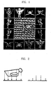
- An example of the DIBR is shown in FIG. 1.
- a point texture and an octree image are different formats of the DIBR family.
- an object is represented by an array of pixels observed at one camera position as shown in FIG. 2.
- Each point texture pixel is represented by a color, a depth corresponding to a distance from a pixel to the camera, and several properties contributing to the point texture visualization.
- the octree image an object is represented by using an octree as shown in FIG. 3, and images on each side are used as reference images.
- McMillan has introduced a warping algorithm capable of producing a visualized view from a new view point without accomplishing a depth test [4]. Now, the McMillan's method will be described in detail.
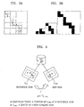
- a world coordinate system is organized according to geometric information of the reference images. For example, a point P1 on the reference coordinate system is transformed into a point P2 on the world coordinate system. From the new view point, the point P2 is viewed as a point P3. The point P3 is obtained by applying a transformation matrix T to the point P1. In order to align points of the reference image on a new view point, an epipolar point is searched.
- the epipolar point corresponds to a center of a new view (that is, a center of a new camera view) projected to the reference image. Moreover, to which of nine regions shown in FIG. 5 the epipolar point is projected is identified, and then a splatting order of the pixels on the reference image is determined according to a sign on a z-axis. If a sequential visualization is performed such that pixels are projected one by one to a new view along rows and columns of a grid array according to the order determined as described above, the depth test becomes unnecessary because the latest mapped pixel always occupies the closest point.
- a direction and an order of drawing pixels in a new image is determined according to the position of the epipolar point on the reference image of the new view and a sign on a z-axis as shown in FIG. 5. According to this method, a back-to-front visualization can be always obtained without the depth test.
- the present invention provides a method and an apparatus for high speed visualization of depth image-based three-dimensional (3D) graphic data represented by one of a simple texture, a point texture, and an octree image to reduce memory usage and increase a visualization speed.
- 3D three-dimensional
- the present invention provides the method of high speed visualization of depth image-based three-dimensional (3D) graphics data, the method comprising: allocating memory to simple texture data consisting of a plurality of reference images; obtaining a plurality of warped images by performing a 3D warping of each of the reference images of the simple texture data at a predetermined view point; obtaining depth data and color data by performing a depth test of each pixel composing the plurality of warped images; and visualizing an object by using the depth data and the color data.
- background data outside a minimum size of square including the object in the reference images may be removed and the minimum size of square including the object may include depth and color data.
- the 3D warping may be performed for only the reference image of which a normal vector has an angle below a predetermined level with respect to a predetermined view vector among a plurality of reference images consisting of the simple texture data.
- Above 3D warping may comprise : searching an epipolar point by projecting a center of an eye coordinate system at a novel view point to the reference image of the simple texture data; determining a warping order for the pixels of the reference images according to which of nine regions defined in the reference image corresponds to a region to which the epipolar point is projected; obtaining the warped image by transforming each coordinate value of a reference coordinate system in which a simple texture has been defined according to the warping order to an eye coordinate system; and iterating from searching an epipolar point to obtain the warped image with respect to the reference images of the simple texture data.
- the coordinate transformation may be accomplished by fixed-point arithmetic operation of a floating-point arithmetic operation.
- the fixed-point arithmetic operation may comprise: converting the floating-point number to the corresponding fixed-point number; performing a coordinate transformation using the converted fixed-point number; and converting the result of the coordinate transformation to a floating-point representation.
- the performing a depth test may comprise : storing depth and color values, obtained by the step of warping for the first reference image, in a front depth buffer and a front color buffer, respectively; storing depth and color values, obtained by the step of warping for the second reference image, in a back depth buffer and a back color buffer, respectively; comparing the depth value stored in the front depth buffer with the depth value stored in the back depth buffer; substituting the depth value stored in the front depth buffer and the color value stored in the front color buffer with the depth value stored in the back depth buffer and the color value stored in the back color buffer, respectively, if the depth value stored in the front depth buffer is larger than the depth value stored in the back depth buffer as a result of the comparison; and iterating from the storing the depth and color values through the substituting the depth and color values with respect to all warping images.
- the step of performing the depth test may further comprise adaptively controlling a splat size depending on a distance from a predetermined view point to a 3D object and the step of visualizing the object is accomplished by using the depth data, the color data, and the appropriately sized splat.
- the step of adaptively controlling the splat size comprises: determining an initial splat size by comparing a resolution of the reference image with a resolution of a destination image; and adjusting the initial splat size according to an enlargement/reduction ratio of a zoom-in/zoom-out operation to create the destination image.
- the splat size may be set to 1 if the resolution of the destination image is smaller than or equal to the resolution of the reference image, and the splat size may be set to an average enlargement aspect ratio if the resolution of the destination image is larger than the resolution of the reference image.
- the splat size may be enlarged by a zoom ratio so as to prevent a "hole" phenomenon during the zoom-in, and reduced by the zoom ratio so as to retain visualization quality of a predetermined level during the zoom-out.
- the method of the high speed visualization of depth image-based 3D graphic data comprising: initializing point texture data of a 3D object; determining a warping order for reference images of the point texture at a predetermined view point according to the position of an epipolar point and a sign of a depth coordinate value; and visualizing the 3D object by using the warping order.
- the step of reading the 3D object may be applied to a method of high speed visualization of the point texture by transforming 3D object data represented by an octree structure to the point texture data and reading the transformed 3D object data.
- the step of reading the 3D object may comprise: decoding the 3D object data represented by an octree structure; projecting voxels of the octree on a predetermined pixel position of a reference surface in a normal direction with respect to the reference surface corresponding to a predetermined surface of a hexahedron including the decoded octree; defining the distance from the voxels to a pixel corresponding to the voxel projected on the reference surface as a depth value; and defining colors of the voxels as color values.
- the step of determining a warping order for reference images of the point texture may be performed after each coordinate value of the reference coordinate system in which the point texture has been defined is transformed to the eye coordinate system when a view point is changed.
- the coordinate system transformation may be accomplished by fixed-point arithmetic operation of a floating-point arithmetic operation.
- the 3D object may be visualized by using the warping order and the adaptively controlled splat size.
- the step of adaptively controlling the splat size may comprises: determining an initial splat size by comparing a resolution of the reference image with a resolution of a destination image; and modifying the initial splat size according to an enlargement/reduction ratio of a zoom-in/zoom-out operation to create the destination image.
- an apparatus for high speed visualization of depth image-based 3D graphic data comprising: a simple texture data memory allocation unit allocating memory to simple texture data consisting of a plurality of reference images; a warping unit performing a 3D warping for each of the reference images of the simple texture of the simple texture data memory allocation unit at a predetermined view point; a depth test unit performing a depth test for each pixel of the plurality of warping images to obtain depth data and color data; and a visualization unit visualizing a 3D object by using the depth data and the color data.
- the warping unit may comprise: an epipolar transformation unit searching an epipolar point by projecting a center of an eye coordinate system at a predetermined view point on the reference images of the simple texture data; a warping order determining unit determining a warping order for the pixels of the reference images according to which of nine regions defined in the reference images corresponds to a region which the epipolar point is projected to; and a pixel warping unit transforming each coordinate value of a reference coordinate system, in which the simple texture has been defined according to the warping order, to an eye coordinate system to obtain the warped images.
- the depth test unit may comprise: a front depth buffer storing a depth value created by the warping for a first reference image; a front color buffer storing a color value created by the step of warping for the first reference image; a back depth buffer storing a depth value created by the step of warping for the second reference image; a back color buffer storing a color value created by the warping for a second reference image; a depth comparison unit comparing the depth value stored in the front depth buffer with the depth value stored in the back depth buffer; and an update unit substituting the depth value stored in the front depth buffer and the color value stored in the front color buffer with the depth value stored in the back depth buffer and the color value stored in the back color buffer, respectively, if the depth value stored in the front depth buffer is larger than the depth value stored in the back depth buffer as a result of the comparison, and iterating the step of storing the depth value and the color value through the step of substituting the depth value and the color value with respect to all the reference images.
- the depth test unit may further comprise a splat unit adaptively controlling a splat size depending on a distance from the predetermined view point to the 3D object, and the visualization unit may visualize the 3D object by using the depth data, the color data, and the appropriately sized splat.
- the splat unit may comprise: a splat size determining unit determining an initial splat size by comparing the resolution of the reference image with the resolution of a destination image; and an adaptive splat unit adjusting the initial splat size according to an enlargement/reduction ratio of a zoom-in/zoom-out operation to create the destination image.
- an apparatus for high speed visualization of depth image-based three-dimensional (3D) graphic data comprising: a point texture initialization unit reading point texture data of a 3D object; a warping order determining unit determining a warping order for drawing pixels of reference images of the point texture at a predetermined view point according to the position of an epipolar point and a sign of a depth coordinate value; a point texture splat unit adaptively controlling a splat size depending on a distance from a predetermined view point to a 3D object; and a visualization unit visualizing the 3D object by using the warping order and the appropriately sized splat.
- the point texture initialization unit may transform 3D object data represented by an octree structure to the point texture data.
- the point texture initialization unit may comprise: an octree decoding unit decoding the 3D object data represented by an octree structure; a depth value computation unit projecting voxels of the octree on a predetermined pixel position of a reference surface in a normal direction with respect to the reference surface corresponding to a predetermined surface of a hexahedron including the decoded octree, and defining distances from the voxels to pixels corresponding to the voxels projected on the reference surface as depth values; and a color value creating unit defining colors of the voxels as color values.
- the reference images of the warping order determining unit may have depth and color data except for background data around a predetermined size of square including an object.
- the warping order determining unit may further comprise a coordinate transformation unit for transforming each coordinate value of the reference coordinate system in which the point texture has been defined to an eye coordinate system.
- the warping order may include: horizontal and vertical warping orders for the pixels of the reference images toward the projected epipolar point; and a depth-axial (z-axis) warping order for the pixels of the reference images, in a back-to-front direction if a depth-axial coordinate value of the epipolar point is positive, or in a front-to-back direction if the depth-axial coordinate value of the epipolar point is negative.
- a computer readable recording medium storing a program for implementing one of the methods described above in a computer.
- the matters of the present invention can be classified into simple texture visualization, point texture visualization, and octree image visualization.
- the simple texture visualization, the point texture visualization, and the octree image visualization commonly are high speed visualization using fixed-point arithmetic operation, adaptive splatting, and techniques of removing background data in a reference image.
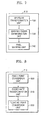
- FIG. 6 shows a block diagram of an apparatus for high speed visualization of depth image-based 3D graphic data according to an embodiment of the present invention.
- the block diagram of the apparatus comprises a simple texture memory allocation unit 600, a warping unit 610, a depth test unit 620, a splat unit 630, and a visualization unit 640.
- the simple texture data memory allocation unit 600 allocates memory to simple texture data containing a plurality of reference images.
- the warping unit 610 performs a 3D warping with respect to simple texture reference images of the simple texture data memory allocation unit 600 to create a plurality of warping images. As shown in FIG. 7, the warping unit 610 comprises an epipolar transformation unit 700, a warping order determining unit 720, and a pixel warping unit 740.
- the epipolar transformation unit 700 searches an epipolar point by projecting a center of an eye coordinate system at a predetermined view point on the reference image.
- the warping order determining unit 720 determines a warping order of pixels of the reference image depending on which of the nine regions defined in the reference image the epipolar point is projected on.
- the pixel warping unit 740 transforms each coordinate value of the reference coordinate system in which the simple texture has been defined to appropriate values of the eye coordinate system according to the warping order and generates a warped image.
- An operation in the warping unit 610 is accomplished by an operation unit comprising a fixed-point conversion unit 800, a coordinate transformation unit 810, and a floating-point conversion unit 820 as shown in FIG. 8.
- the fixed-point conversion unit 800 converts a floating-point representation into the corresponding fixed-point representation.
- the coordinate transformation unit 810 performs a coordinate transformation by using fixed-point number obtained from the fixed-point conversion unit 800.
- the floating-point conversion unit 820 converts the result of the arithmetic operation in the coordinate transformation unit 810 to a floating-point representation.
- the depth test unit 620 performs a depth test with respect to each pixel of a plurality of warping images created by the warping unit 610 to obtain final color data.
- FIG. 9 shows a block diagram of the depth test unit 620.
- the depth test unit 620 comprises a front depth buffer 900, a back depth buffer 910, a depth comparison unit 920, an update unit 930, a front color buffer 940, and a back color buffer 950.
- the front depth buffer 900 stores a depth value formed by a warping of the first reference image.
- the front color buffer 940 stores a color value formed by performing a warping with respect to the first reference image.
- the back depth buffer 910 stores a depth value formed by a warping of the second reference image.
- the back color buffer 950 stores a color value formed by a warping of the second reference image.
- the depth comparison unit 920 compares the depth value stored in the front depth buffer 900 with the depth value stored in the back depth buffer 910. If the value stored in the front depth buffer 900 is smaller than or equal to the value stored in the back depth buffer 910 as a result of the comparison, the update unit 930 leaves the value as it is.
- the update unit 930 substitutes the values stored in the front depth buffer 900 and the front color buffer 940 with the values stored in the back depth buffer 910 and the back color buffer 950, respectively.
- the procedure is iteratively performed for all reference images.
- the splat unit 630 adaptively controls a splat size depending on a distance from a predetermined view point to a 3D object.
- the splat unit 630 comprises a splat size setting unit 1000 and an adaptive splat unit 1050 as shown in FIG. 10.
- the splat size setting unit 1000 determines an initial splat size by comparing a resolution of the reference image with a resolution of a destination image.
- the adaptive splat unit 1050 adjusts the initial splat size depending on an enlargement/reduction ratio of a zoom-in/zoom-out operation to create a destination image.
- the visualization unit 640 visualizes a 3D object by using the depth data, the color data, and the appropriately sized splat.
- FIG. 11 shows a flow chart of an operation in an apparatus for high speed visualization of simple texture data of the depth image-based 3D graphic data. Now, the operation in an apparatus for high speed visualization of simple texture data will be described with reference to FIG. 11.
- the warping is an image processing technique for transforming a reference image represented by using a reference view point to a reference image represented by using other different view point.
- the conventional McMillan's 3D warping algorithm is the method of producing 3D object data visualized in a new view from only one reference image.
- the simple texture of the present invention uses N reference images in order to represent 3D object data. Therefore, the McMillan's 3D warping algorithm can not be directly applied.
- the present invention proposes the method of producing 3D object data and creating target image by performing a warping from N reference images.
- the reference image is represented by a color-image/depth-image pair. Therefore, the simple texture memory allocation unit 600 allocates memory to simple texture data (operation 1100).
- the warping unit 610 performs the warping to create a warped image (operation 1110). More specifically, if the warping is performed for one reference image, an image having corresponding depth information and corresponding color information is created. Needless to say, in this case, the depth test according to a McMillan's algorithm is not performed. Instead, the information is always recorded on the depth buffer and the color buffer.
- the warping is iterated to N images by using the McMillan's algorithm.
- the depth values of each of the N images are determined by the warping.
- a depth relation caused by the warping among the N reference images can not be identified. Therefore, the depth test unit 620 performs a depth test in order to determine the depth relation among the reference images (operation 1120).
- pixels of the finally visualized 3D object data have color values corresponding to the closest depth data to the view point among depth data formed by warping N reference images.
- depth and color values formed by performing a warping of the first reference image are stored in the front depth buffer 900 and the front color buffer 940, respectively.
- results of the warping of the second reference image are stored in the back depth buffer 910 and the back color buffer, respectively.
- the depth comparison unit 920 compares depth values stored in the back depth buffer 910 and the front depth buffer 900 with each other. If the depth value stored in the back depth buffer 910 is smaller than that stored in the front depth buffer 900, the update unit 930 substitutes a color value of a pixel position corresponding to the front color buffer 940 with a color value of a pixel position corresponding to the back color buffer 950.
- the depth value of the back depth buffer is larger than or equal to that of the front depth buffer, the color values of the color buffers are not changed.
- the warping has been applied to all the N reference images.
- an angle between a predetermined view vector created by user's interaction and a normal vector of the reference image is larger than a predetermined angle, the corresponding reference image is not subjected to the warping.
- the predetermined angle is 180 degree, the warping is not accomplished for the perfectly opposite reference images.
- the resolution of the reference image is I R * J R
- the resolution of the new viewing image is I N * J N
- a half of the reference image area is filled with not a background but an object.
- the number of pixels becomes 1/2 * I R * J R , and the depth test is performed for each of the above number of pixels.
- the depth test has to be applied to N reference images.
- N * 1/2 * I R * J R depth tests are accomplished.
- the warping method according to the present invention is applied, the number of pixels constituting one viewing image becomes I N * J N , so that (N-1) *1/2 * (I N * J N ) depth tests are accomplished for N reference images.
- the number of depth tests can be approximated to (I R * J R ) and (I N * J N ). Therefore, the number of depth tests of the warping method according to the present invention is constant. Accordingly, as the resolution of the reference image is getting larger than the resolution of the new viewing image, the number of depth tests is correspondingly getting smaller.
- the method according to the present invention is dependent on the resolution of a destination image regardless of the resolution of an input (reference) image.
- view point changes such as zoom-in/zoom-out frequently occur when a 3D object is visualized in most of 3D applications, the 3D objects or the scenes should be visualized as precise as possible, so that high resolution input images are necessary. Therefore, the method according to the present invention can provide a high quality rendering with a smaller computation load than the conventional method that subjects the high resolution input images to the depth test.
- floating-point arithmetic operation produces more accurate results than fixed-point arithmetic operation, but requires several ten times of a central processing unit (CPU) clock frequency of fixed-point arithmetic operation.
- CPU central processing unit
- a CPU adopted in a mobile terminal such as a personal digital assistant (PDA) or a mobile phone does not support the floating-point arithmetic operation.
- PDA personal digital assistant
- 3D graphic visualization since most operations necessary for a 3D graphic visualization requires floating-point arithmetic operation, high speed visualization is difficult to be achieved in such an environment.
- the floating-point arithmetic operation in the main part of the visualization algorithm is transformed to the fixed-point arithmetic operation to implement integer arithmetic operation, so that the visualization speed can be improved.
- Typical affine transformation in 3-D geometry pipeline has the following format.
- the R matrix represents only rotation (without scaling) and T vector denotes translation. Since R means rotation and we normalize the object inside the unit cubic view volume, the values of each element of R and T are all between -1 and 1.
- M.Nformat is used for the fixed-point numbers. Since the absolute value of the operand is less than 1, 0 bits are allocated to the integer part, i.e. 1.N format is used. Now, let's find the maximum value of N. If two values having such a format are multiplied and stored, 2N bits (except the sign bit) are necessary to avoid the overflow. Similarly, if two values are added and stored, N+1 bits are necessary.
- the number of multiplications between the operands is mostly limited to two times.
- the number of simultaneous additions becomes 3.
- the memory space to store the result is 2N+3bits. If we consider the additional sign bit, we need 2(N + 2) bits.
- this 2(N + 2) should be less than the number of bits in the integer format.
- 32 bits integer is used. Therefore, the maximum of N, i.e. N Max , is 14. In this case, the precision is 2 -14 ( ⁇ 6 ⁇ 10 -5 ) which is sufficiently small.
- each coordinate value is multiplied by 2 N Max to be converted into the fixed-point number in the fixed-point conversion unit 800. Then, the coordinate transformation is performed to achieve the 3-D warping, using the fixed-point arithmetic operation in the coordinate transformation unit 810. As described above, the overflow does not occur in this case. After 3-D warping, the final coordinate value is obtained by converting the integer result back to the floating-point number by dividing 2 N Max in the floating-point conversion unit 820.
- the part to which the fixed-point arithmetic operation is applied is the warping unit 610 where reference coordinates in the reference coordinates system in which the simple texture has been defined is transformed to the eye coordinates system during the visualization process.
- the splat size is adaptively determined, and we will discuss about this.
- the depth test is performed (operation 1120), and then it is examined whether or not the warping and the depth test are accomplished for all the reference images (operation 1130). If the warping and the depth test have been accomplished for all the reference images, the splat size is adjusted according to the present invention (operation1140). And the visualization can be directly performed (operation1150).
- the conventional method uses a triangle as a primitive for visualization but the image-based visualization method uses splatting a point in a 3D space on an image for visualization. And the 3D point as splat has a certain shape and a certain size.
- the present invention proposes a method of implementing an adaptive splat size for the zoom-in/zoom-out with a small amount of computation loads by using properties of an orthographic projection.
- the method according to the present invention can be divided into two procedures.
- the splat size setting unit 1000 compares the resolution of the reference image with a resolution of the destination image to determine an initial splat size.
- the adaptive splat unit 1050 adjusts the initial splat size depending on the enlargement/reduction ratio during the zoom-in/zoom-out to create the destination image.
- the first procedure is to create an initial view having no "hole” phenomenon. If the resolution of the destination image is smaller than or equal to the resolution of the reference image, the initial splat size is set to one. If the resolution of the destination image is larger than the resolution of the reference image, the splat size is set to the average enlargement aspect ratio while the initial view is created. Thus, the created initial view does not have any "hole” phenomenon.
- the zoom-in/zoom-out can be implemented by enlarging/reducing coordinates in the projected image according to zoom-in/zoom-out ratio.
- implementation of these procedures can be obtained by enlarging/reducing the 3D coordinates of an object in only one time according to that ratio.
- the splat size is enlarged/reduced by using that ratio. Therefore, it is possible to prevent the "hole" phenomenon during the zoom-in and to avoid the coarse low quality visualization during the zoom-out in an adaptive manner.
- the present invention techniques for eliminating background data from the reference image are used in order to increase a visualization speed.
- object data typically, only a part of the reference image is used as object data, and the remaining part is used as a background, the meaningless part. This is specifically illustrated in FIG. 17.
- the background data is removed during the memory allocation for the 3D warping and the warping regarded as it is. Therefore, it is possible to reduce memory usage and to improve a visualization speed.
- the background data around a minimum size of square including the object is removed, so that the memory usage is reduced and the visualization speed is improved. Moreover, during storing the reference image, the background data within the minimum size of square is removed except for the object, so that the memory usage is further reduced and the visualization speed is further improved.
- FIG. 12 shows a block diagram of an apparatus for high speed visualization of point texture data of the depth image-based 3D graphic data according to an embodiment of the present invention.
- the apparatus for high speed visualization of point texture data comprises a point texture initialization unit 1200, a warping order determining unit 1210, a point texture splat unit 1220, and a point texture visualization unit 1230.
- the point texture initialization unit 1200 creates a 3D object into point texture data format.
- the warping order determining unit 1210 determines a warping order of drawing pixels according to the position of the epipolar point and the sign of a depth coordinate value at a predetermined view point with respect to the reference image of the point texture. However, since properties of the orthographic projection should be considered unlike the McMillan's warping method, the warping order does not vary depending on the sign of the depth coordinate value of the epipolar point.
- the reference image does not include the background data outside the minimum size of square including an object.
- the warping order determining unit 1210 further comprises a coordinate transformation unit 12.
- the coordinate transformation unit 12 transforms the reference coordinate system in which the point texture has been defined into an eye coordinate system when the view point changes. As shown in FIG.
- the coordinate transformation unit 12 comprises a fixed-point conversion unit 1400 for converting a floating-point number into fixed-point number, a coordinate transformation unit 1410 for performing coordinate transformation by using the converted fixed-point number, and a floating-point conversion unit 1420 for converting the result of the coordinate transformation into a floating-point representation.
- the point texture splat unit 1220 adaptively controls the splat size depending on the distance from the predetermined view point to the 3D object.
- the point texture splat unit 1220 has a similar function and construction to the splat unit 630 described above regarding the simple texture.
- the point texture visualization unit 1230 performs the visualization of a 3D object by using the warping order and the appropriately sized splat.
- the point texture initialization unit 1200 may have two selectable routines, one of which transform 3D object data having an octree construction to point texture data and the other of which confirm point texture data itself, in which the point texture isn't transformed.
- FIG. 13 shows a block diagram for octree data in a point texture initialization unit 1200 for transforming 3D object data to point texture data, which is reorganized for the octree construction.
- the transformation part for octree data in point texture initialization unit 1200 comprises an octree decoding unit 1300, a depth value computation unit 1310, and a color value creating unit 1320.
- the octree decoding unit 1300 decodes the 3D object data represented by an octree construction.
- a predetermined surface of a hexahedron including the decoded octree is defined as a reference surface, and then voxels of the octree are projected on specific pixel positions of the reference surface in a normal direction, so that the distances from the voxels to the a pixel associated with the projected voxel on the reference surface are defined as the depth value.
- the color value creating unit 1320 creates color values of the voxels.
- FIG. 15 is a flow chart illustrating an operation of an apparatus for high speed visualization of point texture data of the depth image-based 3D graphic data according to an embodiment of the present invention. Now, operation according to the present invention will be described.
- the point texture initialization unit 1200 creates point texture data of a 3D object (operation 1500).
- the reference image of the point texture has depth and color data except for the background data outside a minimum size of square region including an object.
- the warping order determining unit 1210 determines a warping order of drawing pixels at a predetermined view point according to a position of an epipolar point with respect to the reference image of the point texture (operation 1510).
- the point texture splat unit 1220 adaptively controls the splat size depending on the distance from a predetermined view point to the 3D object (operation 1520).
- the adaptive control of the splat size is accomplished by determining an initial splat size according to the comparison between the resolution of the reference image and the resolution of the destination image and modifying the splat size depending on the enlargement/reduction ratio of the zoom-in/zoom-out to create the destination image.
- the size of the destination image is reduced according to the enlargement/reduction ratio, and the splat size is set to one.
- the splat size is enlarged by using the enlargement ratio during the zoom-in to prevent the "hole” phenomenon, and is reduced during the zoom-out to retain a predetermined level of visualization quality.
- the 3D object visualization is accomplished by using the warping order determined by the point texture visualization unit 1230 and the appropriately sized splat (operation 1530).
- the warping order follows a direction toward the epipolar point regardless of a sign of the depth coordinate value because of the properties of the orthographic projection unlike the McMillan's warping algorithm adopted by Shade.
- the point texture initialization unit 1200 may create octree-structured data as the point texture data.
- FIG. 13 shows a process of creating the octree-structured data.
- the 3D voxel structure allows even an empty space including no object to have color values, and thus is not efficient.
- a 3D octree voxel structure is adopted to binding voxels according to the octree structure.
- such a 3D octree voxel structure still has a large amount of data. Therefore, in order to visualize them in a high speed, it is necessary to optimize the memory usage and the computation load. Accordingly, if the octree voxel structure is transformed to the point texture, information on only the regions having data is stored, so that the amount of data can be reduced, and data management also can become convenient.
- FIG. 18 is a flow chart illustrating a visualization order of an octree structure.
- the octree structure is received (operation 1800).
- the octree data is decoded to find color values and position values (operation 1810).
- the number of depth data necessary for a particular point if a particular reference surface of the octree is regarded as an image, it is possible to identify the number of depth data necessary for a particular point.
- the number of necessary depth data finally corresponds to the number of layers of the particular point of the created point texture. Therefore, the memory allocation is accomplished for only the same number of layers, and the depth and color values are stored for the created point texture data structure (operation 1820).
- the warping (operation1830) and the splatting (operation1840) are accomplished by using the point texture visualization method as it is after the transformation to the point texture structure, it is possible to reduce the memory usage and improve the visualization speed.
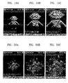
- FIG. 19 shows a visualization result of a BOO image data represented by the simple texture. It is recognized that the "hole" phenomenon is prevented when the splat size is incremented during the zoom-in as shown in FIGS. 19 (a), (b), and (c). However, it is also recognized that an average visualization speed is reduced because one pixel of the reference image has to correspond to a plurality of pixels of the destination screen. This is well illustrated in FIG. 22, which shows quantitative visualization results for the simple texture-based model.
- FIGS. 20 (a), (b), and (c) show a result of the visualization of the flower image represented by the point texture data.
- FIG. 21 (a) and (b) show a result of the visualization of an angel image represented by the octree data.
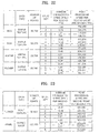
- FIGS. 22 and 23 show quantitative results of the visualization of some image-based models.
- the visualization speed somewhat varies depending on a model type and a splat size, and 500,000 points per a second can be processed for the point texture and the octree image. This corresponds to 1,000,000 triangles per a second for the conventional polygon-based visualization. This performance can not be obtained in mobile terminals until now by using the polygon-based visualization.
- the invention can also be embodied as computer readable codes on a computer readable recording medium.
- the computer readable recording medium is any data storage apparatus that can store data which can be thereafter read by a computer system. Examples of the computer readable recording medium include read-only memory (ROM), random-access memory (RAM), CD-ROMs, magnetic tapes, floppy disks, optical data storage apparatuses, and carrier waves (such as data transmission through the Internet).
- the present invention it is possible to reduce memory usage and increase the number of visualized images per a second because the 3D graphic object represented in an image-based manner is conveniently visualized. Particularly, the visualization of the 3D graphic object can be effectively accomplished when the present invention is applied to mobile terminals.
- the present invention is applied to portable apparatuses because the memory usage and the power consumption for the memory access can be reduced.
- the visualization can be accomplished in a high speed even in a portable apparatus having limited central processing unit (CPU) performance and memory capacity, such as a personal digital assistant (PDA) or a mobile phone as well as a personal computer.
- CPU central processing unit
- PDA personal digital assistant
Landscapes
- Engineering & Computer Science (AREA)
- Physics & Mathematics (AREA)
- Theoretical Computer Science (AREA)
- Computer Graphics (AREA)
- General Physics & Mathematics (AREA)
- Geometry (AREA)
- Textile Engineering (AREA)
- Computing Systems (AREA)
- Image Generation (AREA)
- Processing Or Creating Images (AREA)
Applications Claiming Priority (2)
| Application Number | Priority Date | Filing Date | Title |
|---|---|---|---|
| KR2004008741 | 2004-02-10 | ||
| KR10-2004-0008741A KR100519779B1 (ko) | 2004-02-10 | 2004-02-10 | 깊이영상기반 3차원 그래픽 데이터의 고속 시각화 방법 및장치 |
Publications (2)
| Publication Number | Publication Date |
|---|---|
| EP1564687A2 true EP1564687A2 (fr) | 2005-08-17 |
| EP1564687A3 EP1564687A3 (fr) | 2006-07-12 |
Family
ID=34698967
Family Applications (1)
| Application Number | Title | Priority Date | Filing Date |
|---|---|---|---|
| EP05250685A Withdrawn EP1564687A3 (fr) | 2004-02-10 | 2005-02-07 | Procédé et appareil pour visualisation à grande vitesse des données 3D graphiques basées sur des images de profondeur |
Country Status (5)
| Country | Link |
|---|---|
| US (1) | US7450132B2 (fr) |
| EP (1) | EP1564687A3 (fr) |
| JP (1) | JP2005228320A (fr) |
| KR (1) | KR100519779B1 (fr) |
| CN (1) | CN1655192A (fr) |
Families Citing this family (53)
| Publication number | Priority date | Publication date | Assignee | Title |
|---|---|---|---|---|
| KR100657940B1 (ko) * | 2004-12-28 | 2006-12-14 | 삼성전자주식회사 | 깊이 영상 기반 표현 데이터 압축에 관한 메타표현을이용한 입력파일 생성 방법 및 시스템과, afx부호화방법 및 장치 |
| KR100714672B1 (ko) * | 2005-11-09 | 2007-05-07 | 삼성전자주식회사 | 스플렛을 이용한 깊이 기반의 영상 렌더링 방법 및 그방법을 채용한 시스템 |
| CN100346357C (zh) * | 2006-01-19 | 2007-10-31 | 上海交通大学 | 用三维标记点直接进行三维模型变形的方法 |
| KR100723421B1 (ko) * | 2006-03-13 | 2007-05-30 | 삼성전자주식회사 | 포인트 보간에 의한 렌더링 방법, 포인트 보간에 의한 렌더링 장치 및 기록매체 |
| US20070268289A1 (en) * | 2006-05-16 | 2007-11-22 | Chun Yu | Graphics system with dynamic reposition of depth engine |
| US8134570B1 (en) * | 2006-09-18 | 2012-03-13 | Nvidia Corporation | System and method for graphics attribute packing for pixel shader usage |
| KR101239965B1 (ko) | 2006-11-08 | 2013-03-06 | 연세대학교 산학협력단 | 렌더링 장치 및 방법 |
| KR100858086B1 (ko) * | 2007-01-30 | 2008-09-10 | 삼성전자주식회사 | 렌더링 장치 및 방법 |
| KR100918862B1 (ko) * | 2007-10-19 | 2009-09-28 | 광주과학기술원 | 참조영상을 이용한 깊이영상 생성방법 및 그 장치, 생성된깊이영상을 부호화/복호화하는 방법 및 이를 위한인코더/디코더, 그리고 상기 방법에 따라 생성되는 영상을기록하는 기록매체 |
| KR101526948B1 (ko) * | 2008-02-25 | 2015-06-11 | 삼성전자주식회사 | 3d 영상 처리 방법 |
| US9641822B2 (en) * | 2008-02-25 | 2017-05-02 | Samsung Electronics Co., Ltd. | Method and apparatus for processing three-dimensional (3D) images |
| CN101271583B (zh) * | 2008-04-28 | 2010-04-21 | 清华大学 | 一种基于深度图的快速图像绘制方法 |
| CN102047315B (zh) * | 2008-05-30 | 2015-09-09 | 先进微装置公司 | 可扩展及整合的计算系统 |
| US8379058B2 (en) * | 2008-06-06 | 2013-02-19 | Apple Inc. | Methods and apparatuses to arbitrarily transform windows |
| US20090322747A1 (en) * | 2008-06-30 | 2009-12-31 | Robert Farrell | Graphics processing with hidden surface removal |
| US20110109617A1 (en) * | 2009-11-12 | 2011-05-12 | Microsoft Corporation | Visualizing Depth |
| KR101289269B1 (ko) * | 2010-03-23 | 2013-07-24 | 한국전자통신연구원 | 영상 시스템에서 영상 디스플레이 장치 및 방법 |
| KR20120015165A (ko) * | 2010-08-11 | 2012-02-21 | 엘지전자 주식회사 | 영상의 깊이감 조절 방법 및 이를 이용하는 이동 단말기 |
| JP5812716B2 (ja) * | 2010-08-27 | 2015-11-17 | キヤノン株式会社 | 画像処理装置および方法 |
| WO2012096530A2 (fr) * | 2011-01-13 | 2012-07-19 | Samsung Electronics Co., Ltd. | Appareil et procédé de rendu multi-vues utilisant une expansion de pixel d'arrière-plan et une mise en correspondance de retouche d'arrière-plan en premier |
| WO2012101582A1 (fr) * | 2011-01-24 | 2012-08-02 | Invision Biometrics Ltd. | Procédé et système d'acquisition, de représentation, de compression, et de transmission de données tridimensionnelles |
| CN102737617B (zh) * | 2011-04-01 | 2014-04-30 | 华为终端有限公司 | 视频图像显示的方法和装置 |
| CN102186095B (zh) * | 2011-05-03 | 2012-12-12 | 四川虹微技术有限公司 | 一种适用于深度图像绘制的匹配误差校正方法 |
| EP2627093A3 (fr) * | 2012-02-13 | 2013-10-02 | Thomson Licensing | Procédé et appareil pour insérer une animation graphique 3D dans un contenu stéréo 3D |
| US9256788B2 (en) * | 2012-11-02 | 2016-02-09 | Qualcomm Incorporated | Method for initializing and solving the local geometry or surface normals of surfels using images in a parallelizable architecture |
| JP6041651B2 (ja) * | 2012-12-10 | 2016-12-14 | キヤノン株式会社 | 画像処理装置、画像処理方法及びプログラム |
| US9286647B2 (en) * | 2013-03-12 | 2016-03-15 | Nvidia Corporation | Pixel shader bypass for low power graphics rendering |
| KR20140142470A (ko) | 2013-06-04 | 2014-12-12 | 한국전자통신연구원 | 나무 모델과 숲 모델 생성 방법 및 장치 |
| US10198856B2 (en) * | 2013-11-11 | 2019-02-05 | Oxide Interactive, LLC | Method and system of anti-aliasing shading decoupled from rasterization |
| CN103945206B (zh) * | 2014-04-22 | 2015-08-26 | 冠捷显示科技(厦门)有限公司 | 一种基于相似帧比较的立体图像合成系统 |
| KR102230200B1 (ko) * | 2014-07-04 | 2021-03-19 | 삼성전자주식회사 | 객체에 대한 바운딩 박스의 좌표 값을 표현하는 방법 및 장치 |
| US9948911B2 (en) * | 2014-09-05 | 2018-04-17 | Qualcomm Incorporated | Method and apparatus for efficient depth image transformation |
| US9489710B2 (en) * | 2015-02-10 | 2016-11-08 | Qualcomm Incorporated | Hybrid rendering in graphics processing |
| US10567739B2 (en) | 2016-04-22 | 2020-02-18 | Intel Corporation | Synthesis of transformed image views |
| CN109791696B (zh) * | 2016-08-24 | 2024-04-30 | 苏黎世大学 | 用于场景的3d重建的方法、设备和定位事件摄像机的方法 |
| CN109792537B (zh) * | 2016-09-29 | 2023-06-23 | 皇家飞利浦有限公司 | 用于提供图像的装置和方法以及图像处理装置和系统 |
| EP3428887A1 (fr) * | 2017-07-13 | 2019-01-16 | Thomson Licensing | Procédé et dispositif de codage d'un nuage de points |
| WO2019031386A1 (fr) * | 2017-08-09 | 2019-02-14 | シャープ株式会社 | Dispositif de traitement d'image, dispositif d'affichage, dispositif de transmission d'image, procédé de traitement d'image, programme de commande et support d'enregistrement |
| CN108182656B (zh) * | 2017-12-28 | 2021-04-30 | 深圳市创梦天地科技有限公司 | 一种图像处理方法及终端 |
| KR102068489B1 (ko) * | 2018-03-30 | 2020-01-22 | (주)온넷시스템즈코리아 | 3차원 객체 생성 장치 |
| US10643398B2 (en) * | 2018-07-23 | 2020-05-05 | Microsoft Technology Licensing, Llc | Depth ray layer for reduced visual noise |
| KR102815456B1 (ko) * | 2018-09-12 | 2025-05-30 | 삼성전자주식회사 | 영상 처리를 위한 학습 데이터 생성 방법, 영상 처리 방법, 및 그 장치들 |
| US12014472B1 (en) * | 2019-09-03 | 2024-06-18 | Apple Inc. | Methods and devices for improved inverse iterative warping |
| US11436783B2 (en) | 2019-10-16 | 2022-09-06 | Oxide Interactive, Inc. | Method and system of decoupled object space shading |
| CN112102492B (zh) * | 2020-08-21 | 2022-12-30 | 完美世界(北京)软件科技发展有限公司 | 游戏资源的制作方法及装置、存储介质、终端 |
| KR102635694B1 (ko) * | 2021-07-29 | 2024-02-13 | (주)그래피카 | 3d 고속 렌더링을 위한 3d 데이터 변환 및 사용 방법 |
| US11830140B2 (en) * | 2021-09-29 | 2023-11-28 | Verizon Patent And Licensing Inc. | Methods and systems for 3D modeling of an object by merging voxelized representations of the object |
| CN114429523B (zh) * | 2022-02-10 | 2024-05-14 | 浙江慧脑信息科技有限公司 | 一种控制三维模型分区贴图的方法 |
| CN116958375B (zh) * | 2022-04-20 | 2024-11-19 | 象帝先计算技术(重庆)有限公司 | 图形处理器、系统、装置、设备及方法 |
| CN117745888B (zh) * | 2022-12-29 | 2024-09-24 | 行吟信息科技(武汉)有限公司 | 视频生成方法、装置、电子设备及存储介质 |
| CN116128865B (zh) * | 2023-03-02 | 2026-03-24 | 中南大学 | 一种工业炉窑炉壁温度场数据可视化方法及系统 |
| CN117830175B (zh) * | 2024-03-05 | 2024-06-07 | 暨南大学 | 一种任意取向条件下图像几何扭曲自定标方法 |
| CN118447178B (zh) * | 2024-05-21 | 2024-10-18 | 建设综合勘察研究设计院有限公司 | 一种城市积水的三维动态可视化方法、系统及装置 |
Family Cites Families (12)
| Publication number | Priority date | Publication date | Assignee | Title |
|---|---|---|---|---|
| IL108668A (en) * | 1993-02-25 | 1998-09-24 | Hughes Training Inc | A method and system for creating a plurality of 3D image characters |
| US5409379A (en) * | 1993-10-29 | 1995-04-25 | Southwest Research Institute | Weather simulation system |
| US6466207B1 (en) * | 1998-03-18 | 2002-10-15 | Microsoft Corporation | Real-time image rendering with layered depth images |
| US6999073B1 (en) * | 1998-07-20 | 2006-02-14 | Geometrix, Inc. | Method and system for generating fully-textured 3D |
| US6424351B1 (en) * | 1999-04-21 | 2002-07-23 | The University Of North Carolina At Chapel Hill | Methods and systems for producing three-dimensional images using relief textures |
| JP3504240B2 (ja) * | 2000-07-24 | 2004-03-08 | 株式会社ソニー・コンピュータエンタテインメント | 画像処理システム、デバイス、方法及びコンピュータプログラム |
| US6727908B1 (en) * | 2000-08-31 | 2004-04-27 | Micron Technology, Inc. | Non-linear interpolation scaling system for a graphics processing system and method for use thereof |
| US6756993B2 (en) * | 2001-01-17 | 2004-06-29 | The University Of North Carolina At Chapel Hill | Methods and apparatus for rendering images using 3D warping techniques |
| RU2216781C2 (ru) * | 2001-06-29 | 2003-11-20 | Самсунг Электроникс Ко., Лтд | Основанные на изображениях способ представления и визуализации трехмерного объекта и способ представления и визуализации анимированного объекта |
| US6975756B1 (en) * | 2002-03-12 | 2005-12-13 | Hewlett-Packard Development Company, L.P. | Image-based photo hulls |
| US7215340B2 (en) * | 2002-07-19 | 2007-05-08 | Mitsubishi Electric Research Laboratories, Inc. | Object space EWA splatting of point-based 3D models |
| US7015914B1 (en) * | 2003-12-10 | 2006-03-21 | Nvidia Corporation | Multiple data buffers for processing graphics data |
-
2004
- 2004-02-10 KR KR10-2004-0008741A patent/KR100519779B1/ko not_active Expired - Fee Related
-
2005
- 2005-01-28 CN CNA2005100061171A patent/CN1655192A/zh active Pending
- 2005-02-07 EP EP05250685A patent/EP1564687A3/fr not_active Withdrawn
- 2005-02-08 US US11/052,135 patent/US7450132B2/en not_active Expired - Fee Related
- 2005-02-08 JP JP2005031437A patent/JP2005228320A/ja not_active Withdrawn
Non-Patent Citations (5)
| Title |
|---|
| BAYAKOVSKI Y ET AL: "Depth image-based representations for static and animated 3D objects" PROCEEDINGS 2002 INTERNATIONAL CONFERENCE ON IMAGE PROCESSING. ICIP 2002. ROCHESTER, NY, SEPT. 22 - 25, 2002, INTERNATIONAL CONFERENCE ON IMAGE PROCESSING, NEW YORK, NY : IEEE, US, vol. VOL. 2 OF 3, 22 September 2002 (2002-09-22), pages 25-28, XP010607501 ISBN: 0-7803-7622-6 * |
| GYEONG JA JANG ET AL: "Depth image-based rendering of 3-D object on mobile device" INTELLIGENT SIGNAL PROCESSING AND COMMUNICATION SYSTEMS, 2004. ISPACS 2004. PROCEEDINGS OF 2004 INTERNATIONAL SYMPOSIUM ON SEOUL, KOREA NOV. 18-19, 2004, PISCATAWAY, NJ, USA,IEEE, 18 November 2004 (2004-11-18), pages 630-633, XP010806126 ISBN: 0-7803-8639-6 * |
| LEVKOVICH-MASLYUK L ET AL: "DEPTH IMAGE-BASED REPRESENTATION AND COMPRESSION FOR STATIC AND ANIMATED 3-D OBJECTS" IEEE TRANSACTIONS ON CIRCUITS AND SYSTEMS FOR VIDEO TECHNOLOGY, IEEE SERVICE CENTER, PISCATAWAY, NJ, US, vol. 14, no. 7, July 2004 (2004-07), pages 1032-1045, XP001198603 ISSN: 1051-8215 * |
| OLIVEIRA M M ET AL: "RELIEF TEXTURE MAPPING" COMPUTER GRAPHICS. SIGGRAPH 2000 CONFERENCE PROCEEDINGS. NEW ORLEANS, LA, JULY 23 - 28, 2000, COMPUTER GRAPHICS PROCEEDINGS. SIGGRAPH, NEW YORK, NY : ACM, US, 23 July 2000 (2000-07-23), pages 359-368, XP001003575 ISBN: 1-58113-208-5 * |
| SHADE J ET AL: "LAYERED DEPTH IMAGES" COMPUTER GRAPHICS, July 1998 (1998-07), pages 231-242, XP000934297 * |
Also Published As
| Publication number | Publication date |
|---|---|
| US20050174346A1 (en) | 2005-08-11 |
| US7450132B2 (en) | 2008-11-11 |
| EP1564687A3 (fr) | 2006-07-12 |
| JP2005228320A (ja) | 2005-08-25 |
| CN1655192A (zh) | 2005-08-17 |
| KR100519779B1 (ko) | 2005-10-07 |
| KR20050080650A (ko) | 2005-08-17 |
Similar Documents
| Publication | Publication Date | Title |
|---|---|---|
| US7450132B2 (en) | Method and/or apparatus for high speed visualization of depth image-based 3D graphic data | |
| US6778173B2 (en) | Hierarchical image-based representation of still and animated three-dimensional object, method and apparatus for using this representation for the object rendering | |
| US5613048A (en) | Three-dimensional image synthesis using view interpolation | |
| US10970917B2 (en) | Decoupled shading pipeline | |
| US7450758B2 (en) | Stylization of video | |
| US7027050B1 (en) | 3D computer graphics processing apparatus and method | |
| US6954202B2 (en) | Image-based methods of representation and rendering of three-dimensional object and animated three-dimensional object | |
| US6532013B1 (en) | System, method and article of manufacture for pixel shaders for programmable shading | |
| US20070262988A1 (en) | Method and apparatus for using voxel mip maps and brick maps as geometric primitives in image rendering process | |
| Duguet et al. | Flexible point-based rendering on mobile devices | |
| Schirmacher et al. | High-quality interactive lumigraph rendering through warping | |
| Bonatto et al. | Real-time depth video-based rendering for 6-DoF HMD navigation and light field displays | |
| US5428716A (en) | Solid-clip methodology and architecture for clipping solid models and displaying cross-sections using depth-buffers | |
| Chen et al. | Lod-sprite technique for accelerated terrain rendering | |
| Pajarola et al. | DMesh: Fast depth-image meshing and warping | |
| Kadosh et al. | Tricubic interpolation of discrete surfaces for binary volumes | |
| JP3629243B2 (ja) | モデリング時の距離成分を用いてレンダリング陰影処理を行う画像処理装置とその方法 | |
| EP3876205B1 (fr) | Système et procédé de génération d'image | |
| Schmitz et al. | High-fidelity point-based rendering of large-scale 3-D scan datasets | |
| Papaioannou et al. | Enhancing Virtual Reality Walkthroughs of Archaeological Sites. | |
| US12579732B2 (en) | Face-oriented geometry streaming | |
| Merrin | Dynamic Vertex Hierarchies and View-Based Simplification | |
| de Dinechin et al. | Presenting COLIBRI VR, an Open-Source Toolkit to Render Real-World Scenes in Virtual Reality | |
| Jang et al. | Depth image-based rendering of 3D object on mobile device | |
| Christopoulos et al. | Image-based techniques for enhancing virtual reality environments |
Legal Events
| Date | Code | Title | Description |
|---|---|---|---|
| PUAI | Public reference made under article 153(3) epc to a published international application that has entered the european phase |
Free format text: ORIGINAL CODE: 0009012 |
|
| AK | Designated contracting states |
Kind code of ref document: A2 Designated state(s): AT BE BG CH CY CZ DE DK EE ES FI FR GB GR HU IE IS IT LI LT LU MC NL PL PT RO SE SI SK TR |
|
| AX | Request for extension of the european patent |
Extension state: AL BA HR LV MK YU |
|
| RIN1 | Information on inventor provided before grant (corrected) |
Inventor name: KIM, KEUNHO Inventor name: JUNG, SEOKYOON Inventor name: JANG, GYEONGJA Inventor name: HAN, JOOYEON Inventor name: PARK, INKYUHITECH CENTER 509 |
|
| PUAL | Search report despatched |
Free format text: ORIGINAL CODE: 0009013 |
|
| AK | Designated contracting states |
Kind code of ref document: A3 Designated state(s): AT BE BG CH CY CZ DE DK EE ES FI FR GB GR HU IE IS IT LI LT LU MC NL PL PT RO SE SI SK TR |
|
| AX | Request for extension of the european patent |
Extension state: AL BA HR LV MK YU |
|
| 17P | Request for examination filed |
Effective date: 20061108 |
|
| 17Q | First examination report despatched |
Effective date: 20061228 |
|
| AKX | Designation fees paid |
Designated state(s): DE FR GB NL |
|
| GRAP | Despatch of communication of intention to grant a patent |
Free format text: ORIGINAL CODE: EPIDOSNIGR1 |
|
| STAA | Information on the status of an ep patent application or granted ep patent |
Free format text: STATUS: THE APPLICATION IS DEEMED TO BE WITHDRAWN |
|
| 18D | Application deemed to be withdrawn |
Effective date: 20100519 |