EP1564703A1 - Fahrassistenzsystem für Fahrzeuge - Google Patents
Fahrassistenzsystem für Fahrzeuge Download PDFInfo
- Publication number
- EP1564703A1 EP1564703A1 EP05002825A EP05002825A EP1564703A1 EP 1564703 A1 EP1564703 A1 EP 1564703A1 EP 05002825 A EP05002825 A EP 05002825A EP 05002825 A EP05002825 A EP 05002825A EP 1564703 A1 EP1564703 A1 EP 1564703A1
- Authority
- EP
- European Patent Office
- Prior art keywords
- pedestrian
- vehicle
- solid
- detected
- solid body
- Prior art date
- Legal status (The legal status is an assumption and is not a legal conclusion. Google has not performed a legal analysis and makes no representation as to the accuracy of the status listed.)
- Granted
Links
Images


Classifications
-
- G—PHYSICS
- G06—COMPUTING OR CALCULATING; COUNTING
- G06V—IMAGE OR VIDEO RECOGNITION OR UNDERSTANDING
- G06V20/00—Scenes; Scene-specific elements
- G06V20/50—Context or environment of the image
- G06V20/56—Context or environment of the image exterior to a vehicle by using sensors mounted on the vehicle
- G06V20/58—Recognition of moving objects or obstacles, e.g. vehicles or pedestrians; Recognition of traffic objects, e.g. traffic signs, traffic lights or roads
-
- B—PERFORMING OPERATIONS; TRANSPORTING
- B60—VEHICLES IN GENERAL
- B60W—CONJOINT CONTROL OF VEHICLE SUB-UNITS OF DIFFERENT TYPE OR DIFFERENT FUNCTION; CONTROL SYSTEMS SPECIALLY ADAPTED FOR HYBRID VEHICLES; ROAD VEHICLE DRIVE CONTROL SYSTEMS FOR PURPOSES NOT RELATED TO THE CONTROL OF A PARTICULAR SUB-UNIT
- B60W30/00—Purposes of road vehicle drive control systems not related to the control of a particular sub-unit, e.g. of systems using conjoint control of vehicle sub-units
- B60W30/14—Adaptive cruise control
- B60W30/16—Control of distance between vehicles, e.g. keeping a distance to preceding vehicle
-
- G—PHYSICS
- G08—SIGNALLING
- G08G—TRAFFIC CONTROL SYSTEMS
- G08G1/00—Traffic control systems for road vehicles
- G08G1/16—Anti-collision systems
- G08G1/166—Anti-collision systems for active traffic, e.g. moving vehicles, pedestrians, bikes
-
- G—PHYSICS
- G08—SIGNALLING
- G08G—TRAFFIC CONTROL SYSTEMS
- G08G1/00—Traffic control systems for road vehicles
- G08G1/16—Anti-collision systems
- G08G1/167—Driving aids for lane monitoring, lane changing, e.g. blind spot detection
Definitions
- the present invention relates to a pedestrian detection system for accurately detecting pedestrians to assist driver's driving effectively and a vehicle driving assist system with a pedestrian detection system.
- Japanese Unexamined Patent Application Publication No. 2001-351193 discloses a technique for determining whether pedestrians are present from features of an image in an object region, acquired from an on-board stereo camera, such as object width, longitudinal dispersion, longitudinal barycenter, vertical integrated-value distribution.
- the pedestrian determination technique disclosed in foregoing Japanese Unexamined Patent Application Publication No. 2001-351193 is a method for detecting pedestrians present in the image. Accordingly, also the pedestrians, who need not to be detected, may be detected, such as pedestrians at rest with little possibility of entering a vehicle traveling route. Also, it is a method whereby pedestrians are detected by calculating multiple features only after the entire body of the pedestrians is present in the image, thus having the problem of a delay in determination for pedestrians who enter from the exterior of the image. Furthermore, a load applied to the calculation unit is high, since multiple features are calculated, so that processes to be installed in the calculation unit, other than the pedestrian detection process, are limited and, more advanced and higher-speed image processing is precluded since frame intervals cannot be reduced.
- the present invention has been made in consideration of the above problems. Accordingly, it is an object of the present invention to provide a pedestrian detection system capable of detecting pedestrians who enter the vicinity of a vehicle traveling route rapidly and reliably and informing drivers of it accurately and reducing a calculation load necessary for detecting pedestrians and a vehicle driving assist system including the same.
- a pedestrian detection system includes: imaging means for image picking up a front region to generate an image; solid-body recognition means for recognizing a solid body from the image; and pedestrian determination means for determining whether or not the recognized solid body is a pedestrian.
- the pedestrian detection system further includes: solid-body determination means for determining whether or not a solid body a first end of which in the width direction is detected and a second end is not detected moves to a state in which the second end is detected, thereby specifying a state in which a predetermined region of the image and the solid body come close to each other; solid-body-width detection means for detecting the width of the solid body when the second end is detected; and pedestrian determination means for determining whether or not the solid body is the pedestrian by comparing the width of the solid body with a preset threshold value.
- reference numeral 1 denotes a vehicle such as a car.
- the vehicle 1 mounts an adaptive cruise control (ACC) system 2 as an example of a vehicle driving assist system.
- ACC adaptive cruise control
- the ACC system 2 principally includes a stereo camera 3, a stereo-image recognition unit 4, and a running control unit 5.
- the vehicle runs while maintaining the speed set by the driver in a cruise control mode in which there is no preceding vehicle; while the vehicle is under automatic follow-up control when there is the preceding vehicle.
- the automatic follow-up control for example, when there is the preceding vehicle, vehicle driving information is repeatedly acquired according to the operation by the driver when it is determined that the vehicle follows the preceding vehicle by the driver, thus learning target control values of the automatic follow-up control from the vehicle driving information.
- the automatic follow-up control is executed with the presence of the preceding vehicle, an automatic brake control (including a follow-up stop control), an automatic acceleration control (including a follow-up start control), etc. are performed according to the learned target control values.
- the stereo camera 3 comprises a pair of (left and right) CCD cameras that uses solid-state imaging devices such as charge-coupled devices (CCDs) serving as a stereoscopic optical system.
- CCDs charge-coupled devices
- the left and right CCD cameras are mounted to the front of a ceiling of the vehicle cabin with a fixed space apart from each other, and images an object outside the vehicle in stereo. The image are outputted to the stereo-image recognition unit 4.
- the vehicle 1 includes a vehicle speed sensor 6 for detecting a vehicle speed Vown.
- the vehicle speed Vown is outputted to the stereo-image recognition unit 4 and the travel control unit 5.
- a signal from a turn signal switch 7 of the vehicle is inputted to the stereo-image recognition unit 4, while the ON/OFF signal for a brake pedal from a brake switch 8 of the vehicle 1 is inputted to the travel control unit 5.
- the stereo-image recognition unit 4 acquires data on a solid body in front of the vehicle 1 and information on a region in front of a white line from the image by the stereo camera 3 to estimate a cruising route of the vehicle 1 (vehicle traveling route).
- the stereo-image recognition unit 4 then extracts the preceding vehicle in front of the vehicle 1 and outputs the data on preceding vehicle distance (following, or intervehicle distance) D, preceding-vehicle speed ((variation of the following distance D) + (vehicle speed Vown)) Vfwd, preceding-vehicle acceleration (differential value of the preceding-vehicle speed Vfwd) afwd, the position of a non-moving object other than the preceding vehicle, white-line coordinates, white-line recognition range, vehicle-traveling-route coordinates, etc. to the travel control unit 5.
- preceding vehicle distance following, or intervehicle distance
- preceding-vehicle speed ((variation of the following distance D) + (vehicle speed Vown))
- Vfwd preceding-vehicle acceleration
- the position of a non-moving object other than the preceding vehicle white-line coordinates
- white-line recognition range white-line recognition range
- the image by the stereo camera 3 is processed in the stereo-image recognition unit 4 as follows: Distance information for the entire image of a pair of stereo images in the environment of the vehicle 1 in a traveling direction is acquired from the deviation of corresponding positions on the principle of triangulation, which is imaged by the CCD cameras of the stereo camera 3, thus generating a distance image that shows three-dimensional distance distribution.
- the stereo-image recognition unit 4 performs the known grouping process and extracts white-line data, data on sidewalls such as guardrails and curbs arranged along the roads, and data on solid bodies such as vehicles as compared with stored three-dimensional road-shape data, solid-body data, etc.
- the distance to the solid body and time change of the distance are acquired, in which the closest vehicle on the vehicle traveling route, which cruises in substantially the same direction as the vehicle 1 at a predetermined speed, is extracted as the preceding vehicle.
- the vehicle that comes close to the vehicle 1 at a relative speed to the vehicle 1 substantially the same speed as the vehicle speed Vown is recognized as the preceding vehicle at rest.
- the stereo-image recognition unit 4 detects the pedestrian from the solid bodies acquired from the image by the stereo camera 3 by the pedestrian detection process, shown in Figs. 3 and 4, described later, and outputs signals to an LED 9 and a speaker 10 disposed on an instrument panel to give various warnings according to the position of the pedestrian, vehicle speed Vown at that time, the state of the signal from the turn signal switch 7.
- the various warnings include a warning for attracting the driver's attention (the lighting of the LED 9 and a voice warning from the speaker 10, such as "Be alert for pedestrians”) when the stereo-image recognition unit 4 has determined that there is the pedestrian, wherein when the position of the pedestrian is closer to the vehicle 1 than a predetermined range (a determination range set depending on the vehicle speed Vown).
- the stereo-image recognition unit 4 When the stereo-image recognition unit 4 has determined that the pedestrian is present, wherein when the turn signal switch 7 of the vehicle 1 is in operation, it outputs a warning of the presence of the pedestrian (the lighting of the LED 9 and the voice warning from the speaker 10 such as "Be alert for pedestrians").
- the stereo-image recognition unit 4 when the stereo-image recognition unit 4 has determined that the pedestrian is present, it outputs a signal for canceling automatic follow-up control to the travel control unit 5 of the vehicle 1 and lights up the LED 9 to give a notice that the automatic follow-up control is canceled because of the presence of the pedestrian.
- the stereo-image recognition unit 4 serves as pedestrian detection unit and the stereo camera 3 serves as imaging means.
- the stereo-image recognition unit 4 has the function of solid-body recognition means, solid-body determination means, solid-body-width detection means, and pedestrian determination means.
- the travel control unit 5 achieves the function of cruise control for maintaining a running speed set by the driver and automatic follow-up control, and connects to a cruise control switch 11 including multiple switches connecting to a cruise control operation lever disposed on the side of a steering column etc., the stereo-image recognition unit 4, the vehicle speed sensor 6, the brake switch 8, etc.
- the cruise control switch 11 principally includes a vehicle-speed set switch for setting a target speed during cruise control, a coast switch for principally changing the target speed downward, and a resume switch for principally changing the target speed upward. Furthermore, a main switch (not shown) for turning on/off the cruise control and the automatic follow-up control is disposed in the vicinity of the cruise control operation lever.
- a signal from the cruise control switch 11 is inputted to the travel control unit 5. Then a signal for converging the vehicle speed sensed by the vehicle speed sensor 6 to the speed set by the driver is outputted to a throttle-valve controller 12, where the opening degree of throttle-valve 13 is feedback-controlled, thus driving the vehicle 1 at a constant speed automatically or outputting a deceleration signal to an automatic brake controller 14 to apply an automatic brake.
- the travel control unit 5 can automatically switch the control to automatic follow-up control under predetermined conditions, to be described later, when the stereo-image recognition unit 4 recognizes the preceding vehicle during constant cruise control.
- the distance D between the vehicle 1 and the preceding vehicle is divided by the vehicle speed Vown to calculate the time Td between vehicles, wherein when the state in which the preceding vehicle is present with the automatic follow-up control cancelled (e.g., the main switch in OFF mode) and the time Td between vehicles is within a set value continues for a set time, the travel control unit 5 determines that the vehicle 1 is in follow-up running by the driver.
- vehicle driving information according to the operation of the driver is repeatedly acquired and thus target control values for automatic follow-up control are learned from the vehicle driving information.
- operation signals are outputted to the throttle-valve controller 12 or the automatic brake controller 13 according to the learned target control values.
- the function of the cruise control and the function of the automatic follow-up control are automatically cancelled when the driver steps on the brake, when the vehicle speed Vown has exceeded a predetermined upper limit, and when an automatic follow-up control cancel signal is inputted from the stereo-image recognition unit 4.
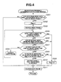
- step (hereinafter, abbreviated to S) 101 a pedestrian detection process is first executed (described later with reference to Figs. 3 and 4). The program proceeds to S102, wherein it is determined as a result of S101 whether or not the pedestrian is present.
- the program proceeds to S103 since the pedestrian is present, it is determined whether or not the position of the nearest pedestrian is close to the vehicle 1 (e.g., within ten meters), wherein when the pedestrian is present far from ten meters, the program proceeds to S104, where a determination range is set depending on the vehicle speed.
- the determination range is stored, for example, in a map and the like, as shown in Fig. 5. The range is set longer, the higher the vehicle speed is.
- the determination range may be corrected depending on the road surface condition (for example, road surface ⁇ if sensed).
- the program proceeds to S105, wherein the distance from the pedestrian and the determination range are compared to each other, wherein, when the pedestrian is present far from the determination range, it is determined that there is no risk of collision with the pedestrian and the procedure comes out of the program. Conversely, when the pedestrian is present within the determination range, it is determined that there is the risk of collision with the pedestrian and the program proceeds to S106, wherein the LED 9 is lit on and also the voice warning such as "Be alert for pedestrians" is outputted from the speaker 10 and the procedure comes out of the program.
- the LED 9 is not necessarily be lit on but may be flashed by varying the frequency depending on the distance from the pedestrian (the flashing cycle is shortened with a decreasing distance from the pedestrian). Also, the shorter the time until the pedestrian is detected by the pedestrian detection process in S101, the shorter the flashing cycle of the LED 9 may be.
- the program proceeds to S107, wherein it is determined whether or not the turn signal switch 7 is in ON state. As a result of the determination, when the turn signal switch 7 is in ON state, the program proceeds to S108, wherein the LED 9 is lit on to inform the driver of the presence of the pedestrian and the speaker 10 outputs the voice warning, such as "Be alert for pedestrians" and the procedure then comes out of the program.
- Fig. 6 assumes a case in which the vehicle 1 is going to turn to the left.
- the driver's eyes are directed to see if vehicles are coming and so the risk of moving the vehicle 1 without watching out for the pedestrian who passes over a crosswalk, opposite to the driver's eyes. According to the embodiment, drivers are informed of the presence of pedestrians even in that case and so, effective driving assist is provided by giving the warning to the drivers.
- the program proceeds to S109, wherein it is determined whether the vehicle 1 is operating automatic follow-up control.
- the program proceeds to S110, wherein the automatic follow-up control is cancelled.
- the program then proceeds to S111, wherein the LED 9 is lit on and the driver is informed of the cancellation of the automatic follow-up control because of the presence of the pedestrian and then the procedure comes out of the program.
- the program proceeds to S112, wherein determination range according to the vehicle speed is set. Also the determination range is stored in a map and the like as shown in Fig. 5, as in S104, and set longer, the higher the vehicle speed is. The determination range may be corrected depending on the road surface condition (for example, road surface ⁇ if sensed).
- the program proceeds to S113, wherein the distance from the pedestrian and the determination range are compared to each other, wherein, when the pedestrian is present far from the determination range, it is determined that there is no risk of collision with the pedestrian and the procedure comes out of the program. Conversely, when the pedestrian is present within the determination range, it is determined that there is the risk of collision with the pedestrian and the program proceeds to S114, wherein the LED 9 is lit on and also the voice warning such as "Be alert for pedestrians" is outputted from the speaker 10 and then the procedure comes out of the program.
- the LED 9 is not necessarily be lit on but may be flashed by varying the frequency depending on the distance from the pedestrian (the flashing cycle is shortened with a decreasing distance from the pedestrian). Also, the shorter the time until the pedestrian is detected, the shorter the flashing cycle of the LED 9 may be.
- the vehicle traveling route (a predetermined region in the image) is estimated from the image by the stereo camera 3.
- the vehicle traveling route is estimated as follows:
- the three-dimensional coordinate system in the actual space is shown as the coordinate system peculiar to the vehicle 1, wherein the lateral (width) direction of the vehicle 1 is indicated by the X-coordinate, the vertical direction of the vehicle 1 is indicated by the Y-coordinate, and the longitudinal direction of the vehicle 1 is indicated by the Z-coordinate.
- the right side of the vehicle 1 is set as the plus side of the X-axis
- the portion above the vehicle 1 is set as the plus side of the Y-axis
- the portion in front of the vehicle 1 is set as the plus side of the Z-axis, with the road surface immediately below the center of the two CCD cameras of the stereo camera 3 as the origin.
- the yaw-rate sensor when the yaw-rate sensor is inoperative, it is determined whether or not the vehicle is steered at a steering angle ⁇ , obtained from the steering-wheel angle ⁇ H, of 0.57 degrees or more.
- the current turning curvature Cua is calculated using the steering angle ⁇ and the vehicle speed Vown, e.g., from equations (2) and (3).
- Re is the turning curvature
- A is a stability factor of the vehicle
- L is a wheel base.
- mean turning curvature is calculated from the turning curvature of past predetermined time (e.g., 0.3 sec.), to which the obtained current turning curvature Cua is added, to estimate the vehicle traveling route.
- the current turning curvature Cua is calculated by the following equation (1), with the yaw-rate sensor in operation, wherein when the steering angle ⁇ is smaller than 0.57 degrees, the current turning curvature Cua may be corrected to 0 (straight driving mode).
- the program then proceeds to S202, wherein it is determined for every left and right boundaries of the image frame for detecting solid bodies whether the pedestrian is present.
- the pedestrian-presence determination process executed every boundaries of the image frame will be described with reference to the flowchart of Fig. 4.
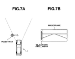
- S301 it is determined whether or not a new solid body with narrow width (e.g., a width from 10 to 300 mm) has been detected at the end of the current image frame.
- Figs. 7A and 7B show an example in which the pedestrian enters forward of the vehicle 1 from the left front relative to the vehicle 1. In that case, as shown in Fig. 7B, the pedestrian is recognized as an object with narrow width on the left of the image frame.
- the program then moves to S304, wherein it is determined whether or not a specific number of frames, or a fixed time (e.g., eight frames at a 100-msec interval, 0.7 sec) has passed after the flag Flag is set in searching the next frame.
- a specific number of frames or a fixed time (e.g., eight frames at a 100-msec interval, 0.7 sec) has passed.
- the state shown in Figs. 7A and 7B or Figs. 8A and 8B has passed by the specific number of frames (the fixed time)
- it is determined that the solid body is not the object coming close to the vehicle 1 (or the solid body at rest).
- the program proceeds to S306, wherein it is determined whether or not the solid body has been detected again in the vicinity of the portion where the solid body was detected in the preceding frame.
- the vicinity of the portion where the solid body was detected in the preceding frame varies depending on the moving speed of the vehicle 1.
- the vehicle speed is corrected by multiplying the vehicle speed Vown by a sampling time ⁇ t (Vown ⁇ t), considering the difference of the detection positions.
- the distance to the solid-body detected position in the current frame relative to the distance to the solid-body detected position in the preceding frame decreases as the vehicle speed Vown increases.
- the solid body is determined as the identical object when the difference from the preceding detected position is within ⁇ 300 mm in consideration of detection error, positional change of the solid body.
- the program proceeds to S307, wherein it is determined whether or not a gap has been detected at the end of the image frame, that is, whether or not the solid body has moved to a state in which the other end can be imaged.
- the state in which the solid body adjacent to the image frame, only one end of which is imaged, shifts to the state in which the other end is also imaged is either the state in which the solid body is moving toward the vehicle traveling route or the state in which the vehicle 1 turns to change in the direction that the vehicle traveling route is closer to the solid object. Accordingly, it can be determined whether or not the cruising route of the vehicle 1 and the object are getting closer to each other by determining whether or not the solid object has moved from the state in which only one end is imaged to the state in which the other end is imaged.
- the pedestrian is determined whether or not the pedestrian is present as soon as the gap is detected at the end of the image frame. This allows the approach of the pedestrian to be sensed accurately and rapidly and also offers high reliability. Also, this prevents the collision due to oversight at right or left turns at intersections or in other cases by calling driver's attention with warnings of the presence of pedestrians.
- the embodiment eliminates unnecessary calculation of image data, thus reducing the load on the calculation unit to speed up the processing. This allows higher accurate image processing, higher detection speed, and multiprocessing operation owing to the reduction of frame intervals, and also cost reduction by introducing a low-performance processing unit.
- the present invention is not limited to that but it is also possible to extract a non-moving solid body which is present in front of the vehicle 1 as a cover object and determine whether or not the solid body only one end of which is detected from the side of the cover object is the pedestrian.
- the non-moving solid body present in the region outside the width of the vehicle traveling route is extracted as the cover object and then the solid body adjacent to the cover object on the vehicle traveling route side, only one end of which is detected, is extracted.
- the cover object and the solid body are extracted for each of the left and right regions of the vehicle traveling route.
- the determination is made on whether or not the gap has been detected between the solid body and the cover object, that is, whether or not the solid body moves to the state in which the other end of the solid body can also be detected. Then it is determined from the width of the solid body whether or not the solid body is the pedestrian, as in the above-described embodiment. This allows rapid detection of the pedestrian who appears from the back of the cover object, making it difficult for drivers to recognize. This also prevents the collision by drawing driver's attention with warnings of the presence of the pedestrian, as in the foregoing embodiment.
- the warning of the presence of the pedestrian of the foregoing embodiment has been described for the warning by the flashing of the LED 9 disposed on the instrument panel and the voice warning from the speaker 10.
- the invention is not limited to that but, for example, the driver may be informed of the presence of the pedestrian in such a manner that the image is displayed on a display disposed at a position that the driver can view and a colored panel is superposed on the portion of the detected pedestrian.
- the pedestrian who enters the vicinity of the vehicle traveling route can be detected rapidly and reliably and the driver can be informed of it accurately and also an operating load necessary for detecting the pedestrian can be reduced.
Landscapes
- Physics & Mathematics (AREA)
- Engineering & Computer Science (AREA)
- General Physics & Mathematics (AREA)
- Multimedia (AREA)
- Mechanical Engineering (AREA)
- Transportation (AREA)
- Automation & Control Theory (AREA)
- Theoretical Computer Science (AREA)
- Traffic Control Systems (AREA)
- Control Of Driving Devices And Active Controlling Of Vehicle (AREA)
- Controls For Constant Speed Travelling (AREA)
- Control Of Vehicle Engines Or Engines For Specific Uses (AREA)
- Length Measuring Devices By Optical Means (AREA)
Applications Claiming Priority (2)
| Application Number | Priority Date | Filing Date | Title |
|---|---|---|---|
| JP2004036996A JP4628683B2 (ja) | 2004-02-13 | 2004-02-13 | 歩行者検出装置、及び、その歩行者検出装置を備えた車両用運転支援装置 |
| JP2004036996 | 2004-02-13 |
Publications (2)
| Publication Number | Publication Date |
|---|---|
| EP1564703A1 true EP1564703A1 (de) | 2005-08-17 |
| EP1564703B1 EP1564703B1 (de) | 2018-05-16 |
Family
ID=34697929
Family Applications (1)
| Application Number | Title | Priority Date | Filing Date |
|---|---|---|---|
| EP05002825.7A Ceased EP1564703B1 (de) | 2004-02-13 | 2005-02-10 | Fahrassistenzsystem für Fahrzeuge |
Country Status (3)
| Country | Link |
|---|---|
| US (1) | US7548634B2 (de) |
| EP (1) | EP1564703B1 (de) |
| JP (1) | JP4628683B2 (de) |
Cited By (10)
| Publication number | Priority date | Publication date | Assignee | Title |
|---|---|---|---|---|
| EP2081131A1 (de) * | 2008-01-18 | 2009-07-22 | Hitachi Ltd. | Objekterkennungssystem |
| EP2202708A1 (de) * | 2008-12-22 | 2010-06-30 | Honda Motor Co., Ltd | Vorrichtung zur Überwachung einer Fahrzeugumgebung |
| EP2214149A2 (de) | 2009-02-03 | 2010-08-04 | Hitachi, Ltd. | Kollisionsvermeidungshilfssystem für Fahrzeug |
| CN102685516A (zh) * | 2011-03-07 | 2012-09-19 | 李慧盈 | 立体视觉主动安全辅助驾驶方法 |
| EP2980389A4 (de) * | 2013-03-29 | 2016-11-30 | Hitachi Automotive Systems Ltd | Wegsteuerungsvorrichtung und wegsteuerungssystem |
| US9994148B1 (en) * | 2016-12-14 | 2018-06-12 | Mando Hella Electronics Corporation | Pedestrian warning device of vehicle |
| CN108263379A (zh) * | 2016-12-30 | 2018-07-10 | 现代自动车株式会社 | 基于姿势信息的行人检测和行人碰撞预防装置和方法 |
| CN108604415A (zh) * | 2016-01-22 | 2018-09-28 | 日产自动车株式会社 | 行人的判定方法和判定装置 |
| CN108873886A (zh) * | 2017-05-10 | 2018-11-23 | 德尔福技术有限公司 | 针对步行人群的自动化车辆控制策略 |
| US20230360238A1 (en) * | 2021-10-27 | 2023-11-09 | Qioptiq Limited | Passive range finder and associated method |
Families Citing this family (36)
| Publication number | Priority date | Publication date | Assignee | Title |
|---|---|---|---|---|
| US7403639B2 (en) * | 2004-11-30 | 2008-07-22 | Honda Motor Co., Ltd. | Vehicle surroundings monitoring apparatus |
| US7489236B2 (en) * | 2005-04-29 | 2009-02-10 | Chavarria Faustino V | Pedestrian alert system for vehicles |
| JP2007091025A (ja) * | 2005-09-28 | 2007-04-12 | Fuji Heavy Ind Ltd | 車両の前方監視装置 |
| US8164628B2 (en) * | 2006-01-04 | 2012-04-24 | Mobileye Technologies Ltd. | Estimating distance to an object using a sequence of images recorded by a monocular camera |
| JP4426535B2 (ja) * | 2006-01-17 | 2010-03-03 | 本田技研工業株式会社 | 車両の周辺監視装置 |
| US20080059069A1 (en) * | 2006-08-30 | 2008-03-06 | Trutna William R | System and method for detecting an object in the path of a vehicle |
| JP2008071062A (ja) * | 2006-09-13 | 2008-03-27 | Fujitsu Ten Ltd | 運転支援装置および通知方法 |
| WO2009061423A2 (en) * | 2007-11-05 | 2009-05-14 | Doubleshot, Inc. | Methods and systems for navigation and terrain change detection |
| JP2009225322A (ja) * | 2008-03-18 | 2009-10-01 | Hyundai Motor Co Ltd | 車両用情報表示システム |
| US8315775B2 (en) * | 2009-02-06 | 2012-11-20 | GM Global Technology Operations LLC | Cruise control systems and methods with adaptive speed adjustment rates |
| JP2010247621A (ja) * | 2009-04-14 | 2010-11-04 | Stanley Electric Co Ltd | 自動車の運転支援システム |
| JP5462609B2 (ja) * | 2009-12-09 | 2014-04-02 | 富士重工業株式会社 | 停止線認識装置 |
| JP5269755B2 (ja) | 2009-12-10 | 2013-08-21 | 株式会社日立製作所 | 人横断支援車両システム及び人横断支援方法 |
| JP5573461B2 (ja) * | 2010-07-27 | 2014-08-20 | トヨタ自動車株式会社 | 車両制御システム |
| WO2012088635A1 (zh) * | 2010-12-30 | 2012-07-05 | 中国科学院自动化研究所 | 车辆自适应巡航控制系统及方法 |
| JP5533766B2 (ja) * | 2011-04-05 | 2014-06-25 | 株式会社デンソー | 車両用表示装置 |
| US9633436B2 (en) | 2012-07-26 | 2017-04-25 | Infosys Limited | Systems and methods for multi-dimensional object detection |
| JP6014440B2 (ja) | 2012-09-26 | 2016-10-25 | 日立オートモティブシステムズ株式会社 | 移動物体認識装置 |
| EP2963633A4 (de) * | 2013-02-27 | 2016-12-07 | Hitachi Automotive Systems Ltd | Objektsensor |
| JP5729416B2 (ja) * | 2013-04-26 | 2015-06-03 | 株式会社デンソー | 衝突判定装置、および衝突緩和装置 |
| DE102013217387A1 (de) * | 2013-09-02 | 2015-03-05 | Siemens Aktiengesellschaft | Verfahren und Vorrichtung zur optimierten stereoskopisch-basierten Entfernungsmessung und deren Verwendung |
| KR101519261B1 (ko) | 2013-12-17 | 2015-05-11 | 현대자동차주식회사 | 차량의 모니터링 방법 및 자동 제동 장치 |
| DE102014003550A1 (de) * | 2014-03-12 | 2014-09-18 | Daimler Ag | Verfahren und Vorrichtung zur Unterstützung eines Fahrers beim Führen eines Fahrzeugs |
| US9718405B1 (en) * | 2015-03-23 | 2017-08-01 | Rosco, Inc. | Collision avoidance and/or pedestrian detection system |
| JP6582936B2 (ja) * | 2015-12-01 | 2019-10-02 | 株式会社デンソー | 経路生成装置、自動走行制御システム |
| CN108604419B (zh) * | 2016-01-29 | 2021-02-09 | 日产自动车株式会社 | 车辆的行驶控制方法及车辆的行驶控制装置 |
| JP6536698B2 (ja) * | 2016-01-29 | 2019-07-03 | 日産自動車株式会社 | 車両の走行制御方法および車両の走行制御装置 |
| KR102441060B1 (ko) * | 2016-12-13 | 2022-09-06 | 현대자동차주식회사 | 보행자 추돌 사고 방지 장치, 그를 포함한 시스템 및 그 방법 |
| JP6642556B2 (ja) * | 2017-11-22 | 2020-02-05 | マツダ株式会社 | 車両の物標検出装置 |
| US10955848B2 (en) | 2018-09-25 | 2021-03-23 | Waymo Llc | Reducing inconvenience to surrounding road users caused by stopped autonomous vehicles |
| JP2019071605A (ja) * | 2018-10-03 | 2019-05-09 | 株式会社ユピテル | 車両用映像記録装置、再生装置、プログラム |
| DE102020006814A1 (de) | 2020-11-06 | 2021-01-14 | FEV Group GmbH | Verfahren zum Vermeiden von fälschlicher Identifikation von Abbildungen von Objekten als reale Objekte für Fahrerassistenzsysteme |
| US12115916B2 (en) | 2021-02-01 | 2024-10-15 | Rosco, Inc. | Downlighting signal and illumination mirror head for vehicle |
| JP7622453B2 (ja) * | 2021-02-03 | 2025-01-28 | トヨタ自動車株式会社 | 運転支援装置 |
| TR202104054A2 (tr) * | 2021-03-02 | 2021-04-21 | Cetin Guel | Trafi̇k ve yaya güvenli̇ği̇ni̇ arttiran bi̇r si̇stem |
| JP2025130218A (ja) * | 2024-02-27 | 2025-09-08 | トヨタ自動車株式会社 | 車両制御装置 |
Citations (9)
| Publication number | Priority date | Publication date | Assignee | Title |
|---|---|---|---|---|
| EP0400607A2 (de) * | 1989-05-31 | 1990-12-05 | Fujitsu Limited | Infrarot-Überwachungssystem |
| US5963148A (en) * | 1995-03-23 | 1999-10-05 | Honda Giken Kogyo Kabushiki Kaisha | Road situation perceiving system |
| JP2001018738A (ja) * | 1999-07-07 | 2001-01-23 | Honda Motor Co Ltd | 車両の周辺監視装置 |
| US6191704B1 (en) * | 1996-12-19 | 2001-02-20 | Hitachi, Ltd, | Run environment recognizing apparatus |
| US6327536B1 (en) * | 1999-06-23 | 2001-12-04 | Honda Giken Kogyo Kabushiki Kaisha | Vehicle environment monitoring system |
| JP2001351193A (ja) | 2000-06-09 | 2001-12-21 | Nissan Motor Co Ltd | 歩行者検知装置 |
| DE10116277A1 (de) * | 2001-03-31 | 2002-10-02 | Volkswagen Ag | Verfahren und Einrichtung zum Erkennen von Objekten im Fahrbetrieb eines Kraftfahrzeuges |
| DE10131720A1 (de) * | 2001-06-30 | 2003-01-16 | Bosch Gmbh Robert | Head-Up Display System und Verfahren |
| US20030218676A1 (en) * | 2002-05-23 | 2003-11-27 | Visteon Global Technologies, Inc. | Image enhancement in far infrared camera |
Family Cites Families (10)
| Publication number | Priority date | Publication date | Assignee | Title |
|---|---|---|---|---|
| US5606534A (en) * | 1989-09-01 | 1997-02-25 | Quantronix, Inc. | Laser-based dimensioning system |
| US5883968A (en) * | 1994-07-05 | 1999-03-16 | Aw Computer Systems, Inc. | System and methods for preventing fraud in retail environments, including the detection of empty and non-empty shopping carts |
| JP4196469B2 (ja) * | 1999-03-02 | 2008-12-17 | マツダ株式会社 | 車両の障害物検出装置 |
| JP2001022938A (ja) * | 1999-07-09 | 2001-01-26 | Nissan Motor Co Ltd | 車両用障害物検出装置 |
| JP3649052B2 (ja) * | 1999-09-07 | 2005-05-18 | 日産自動車株式会社 | 先行車発進検出装置 |
| JP2002056377A (ja) * | 2000-08-08 | 2002-02-20 | Alpine Electronics Inc | 画像認識装置 |
| JP2004508627A (ja) * | 2000-09-08 | 2004-03-18 | レイセオン・カンパニー | 経路予測システムおよび方法 |
| DE10301468B4 (de) * | 2002-01-18 | 2010-08-05 | Honda Giken Kogyo K.K. | Vorrichtung zur Beobachtung der Umgebung eines Fahrzeugs |
| US6791471B2 (en) * | 2002-10-01 | 2004-09-14 | Electric Data Systems | Communicating position information between vehicles |
| US7046128B2 (en) * | 2004-05-26 | 2006-05-16 | Roberts Kristie L | Collision detection and warning system for automobiles |
-
2004
- 2004-02-13 JP JP2004036996A patent/JP4628683B2/ja not_active Expired - Fee Related
-
2005
- 2005-02-04 US US11/051,590 patent/US7548634B2/en not_active Expired - Fee Related
- 2005-02-10 EP EP05002825.7A patent/EP1564703B1/de not_active Ceased
Patent Citations (9)
| Publication number | Priority date | Publication date | Assignee | Title |
|---|---|---|---|---|
| EP0400607A2 (de) * | 1989-05-31 | 1990-12-05 | Fujitsu Limited | Infrarot-Überwachungssystem |
| US5963148A (en) * | 1995-03-23 | 1999-10-05 | Honda Giken Kogyo Kabushiki Kaisha | Road situation perceiving system |
| US6191704B1 (en) * | 1996-12-19 | 2001-02-20 | Hitachi, Ltd, | Run environment recognizing apparatus |
| US6327536B1 (en) * | 1999-06-23 | 2001-12-04 | Honda Giken Kogyo Kabushiki Kaisha | Vehicle environment monitoring system |
| JP2001018738A (ja) * | 1999-07-07 | 2001-01-23 | Honda Motor Co Ltd | 車両の周辺監視装置 |
| JP2001351193A (ja) | 2000-06-09 | 2001-12-21 | Nissan Motor Co Ltd | 歩行者検知装置 |
| DE10116277A1 (de) * | 2001-03-31 | 2002-10-02 | Volkswagen Ag | Verfahren und Einrichtung zum Erkennen von Objekten im Fahrbetrieb eines Kraftfahrzeuges |
| DE10131720A1 (de) * | 2001-06-30 | 2003-01-16 | Bosch Gmbh Robert | Head-Up Display System und Verfahren |
| US20030218676A1 (en) * | 2002-05-23 | 2003-11-27 | Visteon Global Technologies, Inc. | Image enhancement in far infrared camera |
Non-Patent Citations (1)
| Title |
|---|
| PATENT ABSTRACTS OF JAPAN vol. 2000, no. 16 8 May 2001 (2001-05-08) * |
Cited By (19)
| Publication number | Priority date | Publication date | Assignee | Title |
|---|---|---|---|---|
| EP2081131A1 (de) * | 2008-01-18 | 2009-07-22 | Hitachi Ltd. | Objekterkennungssystem |
| EP2202708A1 (de) * | 2008-12-22 | 2010-06-30 | Honda Motor Co., Ltd | Vorrichtung zur Überwachung einer Fahrzeugumgebung |
| US8242897B2 (en) | 2008-12-22 | 2012-08-14 | Honda Motor Co., Ltd. | Vehicle environment monitoring apparatus |
| EP2214149A2 (de) | 2009-02-03 | 2010-08-04 | Hitachi, Ltd. | Kollisionsvermeidungshilfssystem für Fahrzeug |
| EP2214149A3 (de) * | 2009-02-03 | 2010-11-03 | Hitachi, Ltd. | Kollisionsvermeidungshilfssystem für Fahrzeug |
| US8576055B2 (en) | 2009-02-03 | 2013-11-05 | Hitachi, Ltd. | Collision avoidance assisting system for vehicle |
| CN102685516A (zh) * | 2011-03-07 | 2012-09-19 | 李慧盈 | 立体视觉主动安全辅助驾驶方法 |
| EP2980389A4 (de) * | 2013-03-29 | 2016-11-30 | Hitachi Automotive Systems Ltd | Wegsteuerungsvorrichtung und wegsteuerungssystem |
| US10655586B2 (en) | 2013-03-29 | 2020-05-19 | Hitachi Automotive Systems, Ltd. | Running control apparatus and running control system |
| US10503985B2 (en) | 2016-01-22 | 2019-12-10 | Nissan Motor Co., Ltd. | Pedestrian determination method and determination device |
| CN108604415A (zh) * | 2016-01-22 | 2018-09-28 | 日产自动车株式会社 | 行人的判定方法和判定装置 |
| CN108604415B (zh) * | 2016-01-22 | 2020-03-03 | 日产自动车株式会社 | 行人的判定方法和判定装置 |
| US9994148B1 (en) * | 2016-12-14 | 2018-06-12 | Mando Hella Electronics Corporation | Pedestrian warning device of vehicle |
| CN108263379A (zh) * | 2016-12-30 | 2018-07-10 | 现代自动车株式会社 | 基于姿势信息的行人检测和行人碰撞预防装置和方法 |
| CN108263379B (zh) * | 2016-12-30 | 2023-01-10 | 现代自动车株式会社 | 基于姿势信息的行人检测和行人碰撞预防装置和方法 |
| CN108873886A (zh) * | 2017-05-10 | 2018-11-23 | 德尔福技术有限公司 | 针对步行人群的自动化车辆控制策略 |
| CN108873886B (zh) * | 2017-05-10 | 2024-01-23 | 动态Ad 有限责任公司 | 针对步行人群的自动化车辆控制策略 |
| US20230360238A1 (en) * | 2021-10-27 | 2023-11-09 | Qioptiq Limited | Passive range finder and associated method |
| US12450762B2 (en) * | 2021-10-27 | 2025-10-21 | Qioptiq Limited | Passive range finder and associated method |
Also Published As
| Publication number | Publication date |
|---|---|
| US7548634B2 (en) | 2009-06-16 |
| JP2005228127A (ja) | 2005-08-25 |
| EP1564703B1 (de) | 2018-05-16 |
| US20050201590A1 (en) | 2005-09-15 |
| JP4628683B2 (ja) | 2011-02-09 |
Similar Documents
| Publication | Publication Date | Title |
|---|---|---|
| EP1564703B1 (de) | Fahrassistenzsystem für Fahrzeuge | |
| CN109421714B (zh) | 车辆控制系统、车辆控制方法及存储介质 | |
| US9493163B2 (en) | Driving support apparatus for vehicle | |
| CN113291298B (zh) | 车辆的驾驶辅助系统 | |
| JP5952862B2 (ja) | 車両の運転支援装置 | |
| CN109204311B (zh) | 一种汽车速度控制方法和装置 | |
| JP4021344B2 (ja) | 車両用運転支援装置 | |
| JP5345350B2 (ja) | 車両の運転支援装置 | |
| JP6348785B2 (ja) | 車両の運転支援装置 | |
| CN115195775B (zh) | 车辆控制装置、车辆控制方法及存储介质 | |
| US20120185167A1 (en) | Road Shape Recognition Device | |
| US11505193B2 (en) | Vehicle control apparatus, vehicle control method, and storage medium | |
| CN105774806A (zh) | 车辆行驶控制装置 | |
| CN111373460B (zh) | 车辆的物标检测装置 | |
| JP2016009200A (ja) | 車両の運転支援装置 | |
| JP7250837B2 (ja) | 制御装置、制御方法、およびプログラム | |
| KR20190045308A (ko) | 차량 판정 방법, 주행 경로 보정 방법, 차량 판정 장치, 및 주행 경로 보정 장치 | |
| JP3245363B2 (ja) | 車両の衝突防止装置 | |
| WO2019155778A1 (ja) | 衝突回避支援装置、プログラム、衝突回避支援方法 | |
| JP2016009201A (ja) | 車両の運転支援装置 | |
| JPH1139598A (ja) | 車両の衝突防止装置 | |
| JP4235090B2 (ja) | 車両走行支援装置 | |
| JP2010018162A (ja) | 車両の衝突防止装置 | |
| CN112714718A (zh) | 车辆控制方法及车辆控制装置 | |
| JP4294450B2 (ja) | 車両用運転支援装置 |
Legal Events
| Date | Code | Title | Description |
|---|---|---|---|
| PUAI | Public reference made under article 153(3) epc to a published international application that has entered the european phase |
Free format text: ORIGINAL CODE: 0009012 |
|
| AK | Designated contracting states |
Kind code of ref document: A1 Designated state(s): AT BE BG CH CY CZ DE DK EE ES FI FR GB GR HU IE IS IT LI LT LU MC NL PL PT RO SE SI SK TR |
|
| AX | Request for extension of the european patent |
Extension state: AL BA HR LV MK YU |
|
| 17P | Request for examination filed |
Effective date: 20050920 |
|
| AKX | Designation fees paid |
Designated state(s): DE |
|
| 17Q | First examination report despatched |
Effective date: 20081219 |
|
| RAP1 | Party data changed (applicant data changed or rights of an application transferred) |
Owner name: FUJI JUKOGYO KABUSHIKI KAISHA |
|
| RAP1 | Party data changed (applicant data changed or rights of an application transferred) |
Owner name: SUBARU CORPORATION |
|
| GRAP | Despatch of communication of intention to grant a patent |
Free format text: ORIGINAL CODE: EPIDOSNIGR1 |
|
| INTG | Intention to grant announced |
Effective date: 20170925 |
|
| GRAS | Grant fee paid |
Free format text: ORIGINAL CODE: EPIDOSNIGR3 |
|
| GRAA | (expected) grant |
Free format text: ORIGINAL CODE: 0009210 |
|
| AK | Designated contracting states |
Kind code of ref document: B1 Designated state(s): DE |
|
| REG | Reference to a national code |
Ref country code: DE Ref legal event code: R096 Ref document number: 602005053951 Country of ref document: DE |
|
| REG | Reference to a national code |
Ref country code: DE Ref legal event code: R097 Ref document number: 602005053951 Country of ref document: DE |
|
| PLBE | No opposition filed within time limit |
Free format text: ORIGINAL CODE: 0009261 |
|
| STAA | Information on the status of an ep patent application or granted ep patent |
Free format text: STATUS: NO OPPOSITION FILED WITHIN TIME LIMIT |
|
| 26N | No opposition filed |
Effective date: 20190219 |
|
| REG | Reference to a national code |
Ref country code: DE Ref legal event code: R084 Ref document number: 602005053951 Country of ref document: DE |
|
| PGFP | Annual fee paid to national office [announced via postgrant information from national office to epo] |
Ref country code: DE Payment date: 20210217 Year of fee payment: 17 |
|
| REG | Reference to a national code |
Ref country code: DE Ref legal event code: R119 Ref document number: 602005053951 Country of ref document: DE |
|
| PG25 | Lapsed in a contracting state [announced via postgrant information from national office to epo] |
Ref country code: DE Free format text: LAPSE BECAUSE OF NON-PAYMENT OF DUE FEES Effective date: 20220901 |