EP1564766A2 - Pulververbund-Kern und zugehöriges Herstellungsverfahren - Google Patents
Pulververbund-Kern und zugehöriges Herstellungsverfahren Download PDFInfo
- Publication number
- EP1564766A2 EP1564766A2 EP20040460057 EP04460057A EP1564766A2 EP 1564766 A2 EP1564766 A2 EP 1564766A2 EP 20040460057 EP20040460057 EP 20040460057 EP 04460057 A EP04460057 A EP 04460057A EP 1564766 A2 EP1564766 A2 EP 1564766A2
- Authority
- EP
- European Patent Office
- Prior art keywords
- conductive
- magnetic core
- magnetic
- powder composite
- powder
- Prior art date
- Legal status (The legal status is an assumption and is not a legal conclusion. Google has not performed a legal analysis and makes no representation as to the accuracy of the status listed.)
- Withdrawn
Links
Images



Classifications
-
- H—ELECTRICITY
- H01—ELECTRIC ELEMENTS
- H01F—MAGNETS; INDUCTANCES; TRANSFORMERS; SELECTION OF MATERIALS FOR THEIR MAGNETIC PROPERTIES
- H01F41/00—Apparatus or processes specially adapted for manufacturing or assembling magnets, inductances or transformers; Apparatus or processes specially adapted for manufacturing materials characterised by their magnetic properties
- H01F41/02—Apparatus or processes specially adapted for manufacturing or assembling magnets, inductances or transformers; Apparatus or processes specially adapted for manufacturing materials characterised by their magnetic properties for manufacturing cores, coils, or magnets
- H01F41/0206—Manufacturing of magnetic cores by mechanical means
- H01F41/0246—Manufacturing of magnetic circuits by moulding or by pressing powder
-
- H—ELECTRICITY
- H01—ELECTRIC ELEMENTS
- H01F—MAGNETS; INDUCTANCES; TRANSFORMERS; SELECTION OF MATERIALS FOR THEIR MAGNETIC PROPERTIES
- H01F1/00—Magnets or magnetic bodies characterised by the magnetic materials therefor; Selection of materials for their magnetic properties
- H01F1/01—Magnets or magnetic bodies characterised by the magnetic materials therefor; Selection of materials for their magnetic properties of inorganic materials
- H01F1/03—Magnets or magnetic bodies characterised by the magnetic materials therefor; Selection of materials for their magnetic properties of inorganic materials characterised by their coercivity
- H01F1/12—Magnets or magnetic bodies characterised by the magnetic materials therefor; Selection of materials for their magnetic properties of inorganic materials characterised by their coercivity of soft-magnetic materials
Definitions
- the invention concerns method for manufacturing powder composite magnetic core and powder composite magnetic core designed use in electrotechnical appliances, and especially in electrical machines.
- Inductive element and method for producing the same are already known from international patent application WO02/101763.
- Said powder composite is produced by mixing a ferromagnetic amorphous or nanocrystalline alloy powder with a ferromagnetic dielectric powder and a thermoplastic or duroplastic polymer, with dielectric ferromagnetic powder alloy equaling more than 55% by volume.
- Inductive element produced of dielectric ferromagnetic powder is characteristic in that in the mixture of powders, ribbons of ferromagnetic alloy are placed in the mixture of powders.
- powder composite magnetic cores manufactured as components from homogenous mass of compressed magnetic powder composite, wherein the compacted magnetic cores are annealed or sintered following their compacting.
- the method comprises the die being filled with magnetic powder composite, inside of which conductive elements are being placed, and following this procedure magnetic powder composite is bound with inductive elements through compacting.
- conductive elements conductive wires or conductive bars are located in the die.
- Conductive elements of the magnetic core can also be manufactured of conductive powder. To obtain them, the die is being filled with conductive powder and magnetic powder composite.
- the die is simultaneously being filled with conductive powder and magnetic powder composite.
- the die at least once being filled with conductive powder, then at least once with magnetic powder composite or the conductive sheet being placed in the die and then magnetic powder composite is poured over it, and eventually another electrical steel sheet is also placed within the die.
- the essence of the invention concerns inserting at least one conductive element into the compacted magnetic powder composite.
- a conductive wire or a conductive bar is the conducting element.
- the conducting layers is placed on both sides of the compacted powder composite material.
- conductive layers favourably conducting sheet element or compacted conductive powder.
- the magnetic core is of layered arrangement with at least one layer of magnetic powder composite, and at least one layer of conductive powder.
- Conductive elements are placed on the circumference of the magnetic core or along the magnetic core.
- Powder composite magnetic core creates the possibility of producing rotors of electrical machines, rotors of small-power electrical machines, and these of special machines as uniform electromagnetic system. Furthermore, it enables simple change of configuration of conducting elements in order to control the electromagnetic parameters of the circuit already in the process of manufacture.
- FIG. I illustrates hybrid magnetic core made of magnetic powder composites with four conductive wires
- Fig. 2 - hybrid magnetic core made of magnetic powder composites with four conductive bars
- Fig. 3 - hybrid magnetic core made of magnetic powder composites with conductive bars made of conductive powder
- Fig. 4 - layered hybrid magnetic core with one magnetic powder composite layer
- Fig. 5 - layered hybrid magnetic core made of magnetic powder composites with one conductive powder layer
- Fig. 6 - layered hybrid magnetic core made of magnetic powder composites with three conductive elements made of conductive sheet
- Fig. 7 - hybrid magnetic core made of magnetic powder composites with one conductive bar and two conductive wires
- Method for manufacturing powder composite hybrid magnetic core comprises the cubicoid die being filled with magnetic powder composite 1, with four conductive elements in the form of conductive wires being inserted into the die during powder pouring. Subsequently, powder composite material 1 is being bounded with conductive elements 2 through the process of compaction.
- Method for manufacturing powder composite magnetic core proceeds as in example 1, the difference being that four conductive bars of rectangular cross-section are inserted into cubicoid die as conductive elements2.
- Method for manufacturing powder composite magnetic core proceeds as in example 1, the difference being that the die is simultaneously being filled with magnetic powder composite 1 and conductive powder 2.
- Composite magnetic core manufactured this way has four conductive beams each of which is situated along the magnetic core's lateral side.
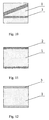
- Method for manufacturing powder composite magnetic core proceeds as in example 1, the difference being that the die is being filled with conductive powder 3, then with magnetic powder composite 1, and finally once again with conductive powder 3.
- Composite powder magnetic core manufactured this way is a layered magnetic core with one compacted magnetic composite layer 1 placed between two layers of compacted conductive powder 3.
- Method for manufacturing powder composite magnetic core proceeds as in example 4, the difference being that the die is being with magnetic powder composite 1, then with conductive powder 3, and once again with magnetic powder composite 1.
- Composite powder magnetic core manufactured this way is a layered magnetic core with one compacted conductive powder layer 3 placed between two layers of compacted magnetic powder 1.
- Method for manufacturing powder composite magnetic core proceeds as in example 1, the difference being that a conductive sheet 2 is inserted into the die which is then filled with magnetic powder composite 1, and finally another conductive steel 2 is also inserted into the die.
- Composite powder magnetic core manufactured this way is a layered magnetic core with two compacted magnetic powder composite layers 1 placed between three conductive sheets elements 2.
- Powder composite magnetic core is manufactured of compacted magnetic powder composite 1 and has three conductive elements 2 - two in the form of conductive bars of circular cross-section and one conductive bar of rectangular cross-section - within the element of compacted magnetic powder composite 1.
- Powder composite magnetic core manufactured as in example 7 the difference being that this type of core has six conductive elements 2 in the form conductive wires.
- Powder composite magnetic core manufactured as in example 7 the difference being that is layered hybrid magnetic core in which conductive layers 3 are placed on both sides of the compacted magnetic powder composite 1.
- the first conductive layer 3 is located along lateral side of the magnetic core, and the second layer 3 is located on its diagonal between the first conductive layer 3 and the opposite side of the magnetic core.
- Powder composite magnetic core manufactured as in example 9 the difference being that the conductive layers 3 are conductive sheet elements.
- Powder composite magnetic core manufactured as in example 11 the difference being that the conductive layer 3 is a layer made of compacted conductive powders.
- Powder composite magnetic core manufactured as in example 9 the difference being that the compacted magnetic powder composite 1 is embedded in the compacted conductive powder 3.
- New method of manufacturing magnetic powder composite allows the manufacture of a magnetic core of any configuration of both the conductive layers 2 and of conductive elements 3 embedded in compacted magnetic powder composite 1.
- the configuration depends on both the requirements and the parameters of the magnetic core which is to be used in electromagnetic system, and because of that the embodiments of the invention show only exemplary hybrid magnetic cores.
Landscapes
- Engineering & Computer Science (AREA)
- Power Engineering (AREA)
- Manufacturing & Machinery (AREA)
- Chemical & Material Sciences (AREA)
- Dispersion Chemistry (AREA)
- Soft Magnetic Materials (AREA)
- Hard Magnetic Materials (AREA)
Applications Claiming Priority (2)
| Application Number | Priority Date | Filing Date | Title |
|---|---|---|---|
| PL364237A PL202424B1 (pl) | 2003-12-24 | 2003-12-24 | Magnetowód z kompozytów proszkowych i sposób wytwarzania magnetowodu z kompozytów proszkowych |
| PL36423703 | 2003-12-24 |
Publications (1)
| Publication Number | Publication Date |
|---|---|
| EP1564766A2 true EP1564766A2 (de) | 2005-08-17 |
Family
ID=34699209
Family Applications (1)
| Application Number | Title | Priority Date | Filing Date |
|---|---|---|---|
| EP20040460057 Withdrawn EP1564766A2 (de) | 2003-12-24 | 2004-12-23 | Pulververbund-Kern und zugehöriges Herstellungsverfahren |
Country Status (2)
| Country | Link |
|---|---|
| EP (1) | EP1564766A2 (de) |
| PL (1) | PL202424B1 (de) |
Cited By (1)
| Publication number | Priority date | Publication date | Assignee | Title |
|---|---|---|---|---|
| DE102007028089A1 (de) * | 2007-06-11 | 2008-12-18 | Würth Elektronik Pforzheim GmbH & Co. KG | Paste zur Herstellung einer Induktivität |
-
2003
- 2003-12-24 PL PL364237A patent/PL202424B1/pl unknown
-
2004
- 2004-12-23 EP EP20040460057 patent/EP1564766A2/de not_active Withdrawn
Cited By (1)
| Publication number | Priority date | Publication date | Assignee | Title |
|---|---|---|---|---|
| DE102007028089A1 (de) * | 2007-06-11 | 2008-12-18 | Würth Elektronik Pforzheim GmbH & Co. KG | Paste zur Herstellung einer Induktivität |
Also Published As
| Publication number | Publication date |
|---|---|
| PL364237A1 (en) | 2005-06-27 |
| PL202424B1 (pl) | 2009-06-30 |
Similar Documents
| Publication | Publication Date | Title |
|---|---|---|
| JP4049246B2 (ja) | コイル封入型磁性部品及びその製造方法 | |
| EP2769391B1 (de) | Vorrichtung zur induktiven übertragung elektrischer energie | |
| DE102020127447A1 (de) | Hybride Ausführung von Statorkernkomponenten für einen Axialflussmotor | |
| EP3921928B1 (de) | Verfahren zur fertigung eines magnetblechs und eines magnetblechstapels sowie elektrische maschine und elektrisches fahrzeug | |
| EP1393330A1 (de) | Induktives bauelement und verfahren zu seiner herstellung | |
| EP3785355A1 (de) | Verfahren zur herstellung einer materiallage und eines materiallagengefüges für eine dynamoelektrische rotatorische maschine | |
| DE112009000919T5 (de) | Verfahren zum Herstellen eines magnetischen Verbundmaterials und magnetisches Verbundmaterial | |
| DE102019123744A1 (de) | Elektrische maschine mit lokal abgestimmten eigenschaften | |
| DE10050703A1 (de) | Verfahren zur Formung von rotierbaren Elektromagneten mit Weich- und Hartmagnetkomponenten | |
| DE2443281A1 (de) | Lamellierter magnetkern | |
| DE102016203739A1 (de) | Paketsystem einer elektrischen Maschine, elektrische Maschine und Verfahren zur Herstellung des Paketsystems | |
| DE102016119654A1 (de) | Verfahren zur Herstellung eines weichmagnetischen Kernmaterials | |
| DE112015002676T5 (de) | Drossel | |
| KR20200124609A (ko) | 합금 분말 조성물, 몰딩들과 몰딩들의 제조 방법, 및 인덕터들 | |
| DE102011111300A1 (de) | Verfahren zur Herstellung eines Halbzeugs für elektrische Kontakte sowie Kontaktstück | |
| JP6708085B2 (ja) | 電子部品 | |
| KR20150008652A (ko) | 연자성 복합 물질, 이의 제조방법, 및 이를 코어재료로 포함하는 전자 부품 | |
| JP5867674B2 (ja) | 圧粉磁心およびその製造方法 | |
| EP1230053B1 (de) | Herstellungsverfahren für ein plattenteil einer elektrischen maschine | |
| EP1564764A2 (de) | Pulververbund-Kern und zugehöriges Herstellungsverfahren | |
| EP3414768A1 (de) | Hybridmagnet und verfahren zu dessen herstellung | |
| EP2626988A2 (de) | Herstellungsverfahren für einen Rotor sowie Rotor | |
| EP1564765A2 (de) | Pulververbund-Kern und zugehöriges Herstellungsverfahren | |
| AT521006B1 (de) | Verfahren zum Herstellen eines Bauteils mit weichmagnetischen Eigenschaften | |
| WO1989007325A1 (fr) | Procede pour fabriquer un element en fer muni d'un enroulement permettant de produire des champs electromagnetiques |
Legal Events
| Date | Code | Title | Description |
|---|---|---|---|
| PUAI | Public reference made under article 153(3) epc to a published international application that has entered the european phase |
Free format text: ORIGINAL CODE: 0009012 |
|
| AK | Designated contracting states |
Kind code of ref document: A2 Designated state(s): AT BE BG CH CY CZ DE DK EE ES FI FR GB GR HU IE IS IT LI LT LU MC NL PL PT RO SE SI SK TR |
|
| AX | Request for extension of the european patent |
Extension state: AL BA HR LV MK YU |
|
| STAA | Information on the status of an ep patent application or granted ep patent |
Free format text: STATUS: THE APPLICATION IS DEEMED TO BE WITHDRAWN |
|
| 18D | Application deemed to be withdrawn |
Effective date: 20070702 |