EP1564770A2 - Ein integrierter Lautstärkeregler und ein Schalter - Google Patents
Ein integrierter Lautstärkeregler und ein Schalter Download PDFInfo
- Publication number
- EP1564770A2 EP1564770A2 EP05075345A EP05075345A EP1564770A2 EP 1564770 A2 EP1564770 A2 EP 1564770A2 EP 05075345 A EP05075345 A EP 05075345A EP 05075345 A EP05075345 A EP 05075345A EP 1564770 A2 EP1564770 A2 EP 1564770A2
- Authority
- EP
- European Patent Office
- Prior art keywords
- resilient
- volume control
- switch
- assembly according
- switch assembly
- Prior art date
- Legal status (The legal status is an assumption and is not a legal conclusion. Google has not performed a legal analysis and makes no representation as to the accuracy of the status listed.)
- Withdrawn
Links
Images

Classifications
-
- H—ELECTRICITY
- H04—ELECTRIC COMMUNICATION TECHNIQUE
- H04R—LOUDSPEAKERS, MICROPHONES, GRAMOPHONE PICK-UPS OR LIKE ACOUSTIC ELECTROMECHANICAL TRANSDUCERS; ELECTRIC HEARING AIDS; PUBLIC ADDRESS SYSTEMS
- H04R25/00—Electric hearing aids
-
- H—ELECTRICITY
- H01—ELECTRIC ELEMENTS
- H01C—RESISTORS
- H01C10/00—Adjustable resistors
- H01C10/30—Adjustable resistors the contact sliding along resistive element
- H01C10/32—Adjustable resistors the contact sliding along resistive element the contact moving in an arcuate path
- H01C10/36—Adjustable resistors the contact sliding along resistive element the contact moving in an arcuate path structurally combined with switching arrangements
-
- H—ELECTRICITY
- H01—ELECTRIC ELEMENTS
- H01H—ELECTRIC SWITCHES; RELAYS; SELECTORS; EMERGENCY PROTECTIVE DEVICES
- H01H3/00—Mechanisms for operating contacts
- H01H3/02—Operating parts, i.e. for operating driving mechanism by a mechanical force external to the switch
- H01H3/0213—Combined operation of electric switch and variable impedance, e.g. resistor, capacitor
-
- H—ELECTRICITY
- H04—ELECTRIC COMMUNICATION TECHNIQUE
- H04R—LOUDSPEAKERS, MICROPHONES, GRAMOPHONE PICK-UPS OR LIKE ACOUSTIC ELECTROMECHANICAL TRANSDUCERS; ELECTRIC HEARING AIDS; PUBLIC ADDRESS SYSTEMS
- H04R2225/00—Details of deaf aids covered by H04R25/00, not provided for in any of its subgroups
- H04R2225/61—Aspects relating to mechanical or electronic switches or control elements, e.g. functioning
-
- H—ELECTRICITY
- H04—ELECTRIC COMMUNICATION TECHNIQUE
- H04R—LOUDSPEAKERS, MICROPHONES, GRAMOPHONE PICK-UPS OR LIKE ACOUSTIC ELECTROMECHANICAL TRANSDUCERS; ELECTRIC HEARING AIDS; PUBLIC ADDRESS SYSTEMS
- H04R25/00—Electric hearing aids
- H04R25/60—Mounting or interconnection of hearing aid parts, e.g. inside tips, housings or to ossicles
- H04R25/603—Mounting or interconnection of hearing aid parts, e.g. inside tips, housings or to ossicles of mechanical or electronic switches or control elements
Definitions
- the present invention relates to an integrated volume control and switch assembly comprising a combined potentiometer and switch function.
- the assembly is suitable for use in hearing aids and portable communication devices.
- Known potentiometers may in addition to a variable resistance function have a built-in switch that provides the option of changing between first and second switch states via the potentiometer knob - typically in an extreme position of the potentiometer knob.
- the potentiometer may function as a volume control where the potentiometer knob upon turning in one direction decreases the volume, and finally turns off the signal and/or switches off power.
- the user is provided with feedback indicating that the switch has reached an off state, e.g. light in a display or diode, a sound, a tactile mechanical resistance towards turning of the knob, or similar.
- volume controls for portable audio equipment feedback is often provided to the user by a tactile feedback upon turning a rotatable volume control knob to or beyond its lowermost position.
- the user has an indication that the device has been switched off so as to save battery without the need for visual confirmation or feedback.
- US 4,081,782, Figs. 7 and 8 shows an integral potentiometer and switch assembly with a resilient tactile member 40, 44 with a detent 44 adapted to provide a user with a tactile feedback upon activating the switch function due to engagement with a dowel 30 which is fixed to a user rotatable member 10.
- the resilient tactile member 40, 44 is formed integral with one switch leg 16.
- a resilient switch member, or blade, 48 is formed integral with another switch leg 14.
- an electrical connection is provided between the two switch legs 14, 16 by a contact area 46 of the resilient switch member 48 engaging with a contact area 42 of the resilient tactile member 40, 44.
- both the resilient tactile member and the resilient switch member form part of the electrical connection between the externally accessible switch legs 14, 16.
- the PJ 88 manufactured and sold by the present applicant is a potentiometer which comprises an integral switch function that provides a tactile feedback upon activation of the switch.
- PJ 88 is suited for miniature applications, such as a combined volume control and on/off switch in a hearing aid.
- the combined switch function and tactile feedback is provided by engagement of two metal springs upon interaction with a protrusion on a user rotatable part.
- the two metal springs are both engaged with the tactile feedback function as well as with the switch function since, in one switch state, the two metal springs are both engaged in providing an electrical connection between two externally accessible switch legs.
- One object of the present invention is to provide an integrated volume control and switch assembly of a simple design that provides tactile feedback to a user of the assembly in connection with the switch function.
- the assembly must be suited for miniature applications, such as hearing aids, and still suited for cost efficient production.
- An additional object is to provide an integrated volume control and switch assembly providing independently adjustable switch and feedback functions.
- an integrated volume control and switch assembly comprising
- the first and second conductive switch legs may have different shape than elongate slim members or pins.
- the switch legs may be formed by conductive bumps adapted for soldering or they may be formed by pieces of Printed Circuit Boards (PCB), pieces of flexprint or flexible wires etc.
- PCB Printed Circuit Boards
- the switch legs may alternatively be formed by conducting material being bent around an edge of the base plate and thus obtaining in essence the same effect, namely establishing an electrical connection from a first side to a second side of the base plate.
- the resilient conductive member and the resilient tactile member are formed by separate members.
- the assembly in miniature versions without the need for components being so small that they are difficult to handle in a mass production line.
- the resilient tactile member does not form part of the electrical connection in the first switch state.
- the tactile feedback function can be physically separate from the switch function.
- the separate members can be independently positioned in the assembly thus allowing each member to be located in positions with more space available.
- an additional advantage is that the independent switch function and tactile feedback function allows an independent choice of the respective angular positions of the rotatable member for effecting the change between switching states and for effecting the tactile feedback.
- the integral volume control and switch assembly may have the resilient tactile member (35) and the resilient conductive member (8) spatially separated along a rotational axis of the rotatable member (40).
- the resilient conductive member (8) and the switch legs (2,3) may constitute separate members.
- the assembly may further comprise an intermediate link (20) rigidly connected to the rotatable member (40), the intermediate link (20) comprising a protrusion (21) being adapted to engage with the resilient conductive member (8) so as to either establish or break the electrical connection between the first (2) and second (3) switch legs.
- the assembly may further comprise an intermediate housing (30) part being rigidly connected to the base plate (1), the intermediate housing part (30) having a top portion aligned with the base plate (1), wherein the top portion supports the resilient tactile member (35).
- the top portion of the intermediate housing part (30) may comprise an indentation (32) for guiding a first part (35a) of the resilient tactile member (35).
- the rotatable member (40) may comprise at least one protrusion (39) adapted to engage with an engaging part (38) of the resilient tactile member (35).
- the first part (35a) of the resilient tactile member (35) may be substantially U-shaped, and said first part (35a) being substantially perpendicular to the engaging part (38).
- the at least one protrusion (39) of the rotatable member (40) may be adapted to engage with the resilient tactile member (35) so as to provide an audible feedback signal in addition to the tactile feedback.
- the predetermined angular position of the rotatable member (40) may be different from or equal to an angular position of the rotatable member (40) causing the resilient conductive member (8) to switch between the first and second switch states.
- the resilient conductive member (8) may comprise a first part (9a, 9b) adapted to engage with the protrusion (21) of the intermediate link (20).
- the resilient conductive member (8) may comprise a detent spring manufactured in a material selected from the group consisting of: stainless steel, spring steel, low carbon steel, metallic alloys and Palladium alloys.
- the resilient conductive member (8) may be manufactured monolithically.
- the resilient tactile member (35) may comprise a detent spring manufactured in a material selected from the group consisting of: stainless steel, spring steel, low carbon steel, and Palladium alloys.
- the resilient tactile member (35) may be manufactured monolithically.
- the assembly may further comprise a user operable knob (50) connected to the rotatable member (40), the user operable knob (50) comprising means for providing friction with a user's finger.
- the base plate (1) may be manufactured in a material selected from the group consisting of: heat resistive thermoplastics, insulating ceramics, LCP, PVC, PE, PP, and Polyetheretherketone.
- the intermediate housing part (30) may be manufactured in a material selected from the group consisting of: insulating ceramics, PVC, PE, PP, and Polyamide.
- variable resistance means may comprise
- variable resistance means may further comprise a fifth conductive leg (12) electrically connected to a second end portion of the conductive path (14).
- the substrate (10) supporting the conductive path (14) may comprise a PCB.
- leg is not limiting with respect to third, fourth and fifth conductive legs (11,12,13).
- conductive legs (11,12,13) may also be shaped as for example flexible wires, flexprint or bumps etc.
- An outer diameter of the assembly may be in the range 1-4 mm, preferably in the range 2-3 mm.
- an outer diameter is understood an outer diameter including a suitable outer protective housing part of the volume control and switch assembly.
- a total height of the assembly is in the range 1,5-4,5 mm, preferably in the range 2,5-3,5 mm.
- the invention in a second aspect, relates to a hearing aid comprising an integral volume control and switch assembly according to the first aspect.
- the invention in a third aspect, relates to a portable communication device comprising an integral volume control and switch assembly according to the first aspect.
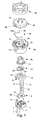
- Fig. 1 shows a perspective view of selected parts of the assembly according to the invention showing from below a base plate 1 comprising first 2 and second 3 conductive switch legs.
- the first 2 and second 3 conductive switch legs penetrate the base plate 1 and form two terminals 4, 5, respectively, on an upper surface of the base plate 1.
- the switch legs 2,3 may be formed by conductive bumps adapted for soldering or they may be formed by pieces of Printed Circuit Boards (PCB), pieces of flexprint or flexible wires.
- PCB Printed Circuit Boards
- the base plate 1 further comprises three holes 6 for receiving third 11, fourth 13, and fifth 12 conductive legs mounted on substrate 10. These legs 11,12,13 form the termination of the 3-pin potentiometer part of the assembly. One of conductive legs 11 or 12 may be omitted, if preferred, thus leaving the potentiometer part in a 2-pin version providing an adjustable resistance value between the two legs 11,13 or 12,13.
- the base plate 1 also comprises an indentation 7 fitted to receive and support a resilient conductive member 8.
- the resilient conductive member 8 is a detent spring having a first part 9c positioned in the indentation 7 and second parts 9a, 9b oriented substantially perpendicular to the first part 9c.
- the second part 9a of the resilient conductive member 8 is intended to co-operate with a protrusion 21 of the intermediate link 20, in order to change switch state, i.e. establish or break the electrical connection between the two terminals 4, 5 and hence the first 2 and second 3 conductive switch legs.
- the indentation 7 is preferably wider near the point of engagement between the resilient conductive member 8 and the protrusion 21 so as to allow bending of the first part 9c of the resilient conductive member 8 positioned in the indentation 7.
- the substrate 10 comprises a conductive path 14 on a surface thereof.
- Third and fourth conductive legs 11, 12 penetrate the substrate 10 so as to be electrically connected to opposite end portions of the conductive path 14.
- the fifth conductive leg 13 is preferably positioned near the centre of the substrate 10 as the fifth conductive leg 13 is adapted to be in electrical contact with a centre mounted contact element 23 of a slidable contact 22 formed as a wiper, the slidable contact 22 further having a contact point 24 adapted for electrical contact with the conductive path 14.
- the substantially circular substrate 10 comprises an indentation 16 so as to let the second part 9a, 9b of the resilient conductive member 8 extend above the substrate 10.
- the intermediate link 20 has the slidable contact 22 rigidly mounted to its lower side.
- the conductive legs 11, 12, 13, the conductive path 14, and the slidable contact 22 are capable of constituting a conventional voltage divider where the rotation of the conductive wiper 22 provides two mutually dependent variable resistance values between the third conductive leg 11 and the fifth conductive leg 13, and between the fourth conductive leg 12 and the fifth conductive leg 13, respectively.
- the intermediate link 20 comprises a protrusion 21 adapted to engage with the second part 9b of the resilient conductive member 8.
- the protrusion 21 is preferably manufactured in a material appropriate for the engagement with the resilient conductive member 8, such as insulating ceramics, PVC, PE, PP or similar. Polyamide 6.6 with 50% glass is a preferred choice of material for the intermediate link 20.
- the intermediate link 20 and the protrusion 21 are manufactured, e.g. moulded, in one piece to simplify manufacturing.
- An intermediate housing part 30 comprises a through-going opening 31 suited for receiving and preferably supporting the intermediate link 20 in such a way as to allow the intermediate link 20 to rotate at least part of a full revolution.
- the intermediate housing part 30 preferably comprises a U-shaped indentation 32 adapted to receive and support a resilient tactile member 35 formed as a detent spring.
- the leg parts of the U-shaped indentation 32 are wider than the bottom part of the U-shaped indentation 32 so as to allow bending of a first part 35a of the resilient tactile member 35 when positioned in the leg parts of the U-shaped indentation 32.
- the resilient tactile member 35 comprises a second part 38 oriented substantially perpendicular to the first part 35a.
- the intermediate housing part 30 preferably comprises a projection part 36 that supports the rotatable member 40.
- the projection part 36 serves as stopping means by preventing damage of the assembly that would occur by overturning the rotatable member 40.
- a protrusion 39 (further described in the following) of the rotatable member 40 will at one point of the rotation engage with the projecting part 36 that will thus hinder further rotation of the rotatable member 40 in the same direction.
- the intermediate housing part 30 also comprises an outer projection 33 for easy and reliable mounting/fixing of the assembly in a device, such as in a face plate of a hearing aid.
- the resilient conductive member 8 is formed as a separate member from the contact parts 4,5 with which the resilient conductive member 8 is adapted to engage. If preferred, the switching mechanism according to the invention may be arranged so that the resilient conductive member 8 can be formed integral with one of the contact parts 4,5 and consequently integral with one of the conductive switch legs 2,3.
- a rotatable member 40 is rigidly connected to the intermediate link 20 in order to transfer rotational displacement of the rotatable member 40 to the intermediate link 20.
- the rigid connection is established by designing the rotatable member 40 and the intermediate link 20 to be combined or forced together in a locking engagement.
- the rotatable member 40 and the intermediate link 20 are joined by welding, gluing or similar.
- Rotation of the rotatable member 40 and the intermediate link 20 is preferably performed around a substantially central axis of the assembly.
- the fifth conductive leg 13 is also positioned in the axis of rotation.
- a knob 50 for user friendly interaction may be provided on top of the rotatable member 40 so as to allow a user to easily operate the assembly.
- the knob 50 is preferably joined to the rotatable member 40 by fastening on a central projection 41 of the rotatable member 40 and an indentation 42 of the rotatable member 40, e.g. by a locking engagement or similar methods.
- the knob 50 shown has a number of wings adapted to provide sufficient friction to a user's finger during operation.
- the knob 50 may be omitted if preferred or made integral with the rotatable member 40.
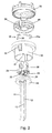
- Fig. 2 shows a different perspective view of selected parts of the assembly according to the invention.
- Bottom part of the rotatable member 40 comprises an opening 44 adapted to fit to a top of the intermediate link 20.
- the rotatable member 40 also comprises a protrusion 39 adapted to engage with the second part 38 of the resilient tactile member 35 upon rotation of the rotatable member 40. It is apparent that an angular position of the tactile engagement relative to an angular position of the top member 40 where a change of switch state occurs can be chosen with a high degree of freedom. Thus, a timing experienced by the user between change of switch state and tactile feedback upon rotation of the rotatable member 40 can be varied.
- This timing corresponds to an angular difference of the rotatable member 40 between the point of engagement of the protrusion 39 and the second part 38 of the resilient tactile member 35 versus the point of engagement of the protrusion 21 of the intermediate link 20 with the second part 9b of the resilient conductive member 8.
- the angular difference between change of switch state and tactile feedback can be adjusted on the shown embodiment in several ways.
- the rotatable member 40 may be turned into another angular position when locked into engagement with the intermediate link 20.
- Another way to adjust the switch function in relation to the tactile feedback is by providing a rotatable member 40 with its protrusion 39 positioned at another angular position relative to its locking mechanism for engagement with the intermediate link 20.
- Still another way of adjusting the switch function in relation to the tactile feedback is by providing an intermediate link 20 with its protrusion positioned at another angular position relative to its locking mechanism for engagement with the rotatable member 40.
- the detailed kind of engagement between the protrusion 39 and the second part 38 of the resilient tactile member 35 can be performed in a variety of ways and a variety of tactile and also acoustic effects experienced by a user can be obtained. Due to the fact that the tactile feedback arrangement, formed by the resilient tactile member 35 and the protrusion 39, is separated from the switch arrangement formed by the protrusion 21 of the intermediate link 20 actuating the second part 9b of the resilient conductive member 8, a variety of different schemes for timing of tactile feedback relative to the electrical switch function can be provided. Only a few examples will be given below.
- the protrusion 39 has a slope as viewed in a profile view that bends the second part 38 of the resilient tactile member 35 away from its equilibrium position upon engagement.
- the engagement provides the user with an increasing mechanical resistance towards rotation of the rotatable member 40 depending on the rate of increase of the slope and a stiffness of the resilient tactile member 35.
- the stiffness of the second part 38 of the resilient tactile member 35 but also a stiffness of the first part 35a of the resilient tactile member 35 influences the mechanical resistance that will be experienced by the user.
- the slope of the protrusion 39 has a linear slope, but as an alternative to a linear slope, the slope might have a concave shape, a convex shape, a step-ladder shape, or similar.
- a surface of the protrusion 39 is coated or treated to facilitate different kinds of engagement with the second part 38 of the resilient tactile member 35.
- the intermediate link 20 is fitted to the opening 31 in the intermediate housing part 30 substantially water-tight. This is crucial for example for hearing aid applications where it is essential that the volume and switch assembly is capable of reliable operation in a humid environment, i.e. the assembly needs to be at least substantially sweat-tight.
- the protrusion 39 has a maximum as viewed in a profile view.
- the user experiences an initially increasing mechanical resistance towards rotation of the rotatable member 40 being similar to the first embodiment described above.
- the mechanical resistance will decrease relatively upon further rotation of the rotatable member 40, thus providing the user with a different type of tactile feedback relative to the first embodiment.
- the protrusion 39 has more than one maximum as viewed in a profile view.
- the protrusion 39 has an abrupt or discontinuous maximum following by a steep decline as viewed in a profile view.
- the steep decline allows the second part 38 of the resilient tactile member 35, at least for a short period of time, to accelerate towards a stop part of the protrusion 39 to provide a mechanical impact by the second part 38 of the resilient tactile member 35 on said stop of the protrusion 39.
- This mechanical impact will result in an audible sound to the user, thereby informing the user about the change of switch state of the assembly via an audible click sound.
- the audible sound is combined with a mechanical tactile feedback.
- the protrusion 39 is specifically treated or prepared at the point of the mechanical impact to enhance the audible sound.
- the protrusion may e.g. be metallised or similarly.
- the rotatable member 40 and/or the knob 50 may be designed specifically with respect to enhance their ability to transmit vibrations resulting from mentioned impact so as to enhance the acoustic signal radiated by external elements of the assembly, such as the knob 50.
- the resilient conductive member 8 as well as the resilient tactile member 35 are formed by metal wire bent into a desired shape. In this way the resilient property of the resilient members 8, 35 is provided by a spring effect.
- the resilient conductive member 8 is preferably formed by an electrically conductive material.
- the resilient members 8, 35 may be formed by different materials.
- the resilient tactile member 35 may be formed in an electrically non-conductive material such as a polymeric material that is capable of providing a spring effect so as to provide a tactile sensation to a user upon interaction of the resilient tactile member 35 with the protrusion 39 of the rotatable member 40.
- Preferred materials for the resilient conductive member 8 is Paliney 6, i.e. a Palladium-Silver based alloy.
- Another suitable material for the resilient conductive member 8 is Hera, which is a Palladium, Copper, Silver and Nickel based alloy.
- the same materials mentioned for the resilient conductive member 8 are also suitable for the slidable contact 22.
- the resilient tactile member 35 is preferably manufactured in stainless steel such as W No. 1.4310. At least the material for the resilient tactile member 35 must provide a spring effect. All terminals, i.e. conductive switch legs 2, 3 as well as conductive legs 11, 12, 13 are preferably manufactured in a silver alloy plated with 2 ⁇ m gold, such as AgCu 97/3.
- Preferred materials for intermediate link 20, intermediate housing part 30, rotatable member 40 as well as knob 50 is Ultramid A3EG10, i.e. Polyamide 6.6 comprising 50% glass.
- Materials for the base plate 1 must be able to withstand heat from welding.
- a preferred material for the base plate 1 is Victrex PEEK GL30, i.e. Polyetheretherketone comprising 30% glass.
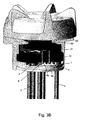
- Figs. 3A and 3B show the assembly according to the invention in a first and a second switch state, respectively, both viewed in a partly cut-away section.
- Fig. 3A shows one leg 9a of the first part 9a, 9b of the resilient conductive member 8 being in electrical contact with the upper contact terminal 5, the contact terminal 5 forming an upper part of the conductive leg 3.
- the contact terminal 4 is in electrical contact with another leg 9b of first part 9a, 9b of the resilient conductive member 8, hence an electrical contact between the first 2 and second 3 conductive legs is established in this first switch state of operation.
- Fig. 3A it is also apparent how the contact part 24 of the wiper 22 co-operates with the conductive path 14 on the substrate 10 in order to establish electrical contact between a point of the conductive path 14 and the fifth conductive leg 13.
- the two second parts 9a, 9b of the resilient conductive member 8 fit in the indentation 16 of the substrate 10 and extend above the substrate 10 to facilitate possible engagement by the protrusion 21 (not shown in Fig. 3A) of the intermediate link 20.
- Fig. 3B shows the knob 50, the rotatable member 40 (not visible in Fig. 3B), and the intermediate link 20 turned clockwise approximately a quarter of a full rotation relative to the position illustrated in Fig. 3A, and thus Fig. 3B illustrates the second switch state of operation.
- the protrusion 21 of the intermediate link 20 is engaged with the second part 9a of the resilient conductive member 8, thus forcing this second part 9a of the resilient conductive member 8 away from the contact terminal 5, and hence the electrical connection between the contact terminals 4 and 5 is broken in this second switch state of operation. Consequently, electrical connection between conductive switch legs 2,3 is broken in the second switch state.
- the assembly can be brought into the same switch state by turning the rotatably mounted elements 20, 40 and 50 in the opposite direction so that the protrusion 21 engages with the other leg 9b of the second part 9a, 9b of the resilient conductive member 8 so as to break the electrical connection between the contact terminal 4 and the resilient conductive member 8.
- the assembly is designed with appropriate stopping means, such as a projection part 36, so that overturning of the knob 50 and consequently the rotatable member 40 and intermediate link 20 is prevented as this could damage at least the second part 9a, 9b of the resilient conductive member 8.
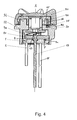
- Fig. 4 shows a cross-sectional view through the centre of an assembled embodiment of the assembly according to the invention with the axis A of rotation indicated.
- the central conductive leg 13 penetrates the base plate 1 and the substrate 10 so as to provide electrically contact to the central part 23 of the wiper 22.
- the second part 9a of the resilient conductive member 8 extends with an end portion above the substrate 10 while another part 9c of the resilient conductive member 8 resides in the dedicated indentation 7 of the base plate 1.
- the intermediate link 20 is rotatably mounted in the intermediate housing part 30 and the intermediate link 20 is rigidly connected with the rotatable member 40.
- the rotatable member 40 is rigidly connected to the knob 50.
- a part 35a of the resilient tactile member 35 is shown positioned in the indentation 32 of the intermediate housing part 30.
- the second part 38 of the resilient tactile member 35 can move freely in the cavity 45 of the rotatable member 40 until the second part 38 of the resilient tactile member 35 engages with a protrusion 39 (not visible in Fig. 4) of the rotatable member 40.
- the size of the projection 36 is larger than the size of the cavity 45. Therefore, full rotation of the rotatably mounted parts 20, 40, and 50 is prevented.
- the projecting part 36 will meet a part of the cavity 45 of the rotatable member 40 being smaller than the projecting part 36, and thus further rotation of the rotatable member 40 relative to the intermediate housing part 30 is hindered.
- the rotatable member 40 is seen from below, and it is seen that the projecting part 36 will be stopped when reaching the protrusion 39.
- other positions may be chosen for position of a stop member, for example so as to allow only a small fraction of a full rotation of the rotatable member 40 relative to the intermediate housing 30.
- a volume control and switch assembly according to the invention and according to the shown embodiments may be manufactured in a variety of sizes adapted to fit into different miniature applications such as portable audio devices for entertainment such as portable MP3 players, CD players or portable radios.
- the assembly may also be manufactured in sizes small enough to fit hearing aid applications while still acceptable with respect to large scale manufacturing.
Landscapes
- Engineering & Computer Science (AREA)
- Microelectronics & Electronic Packaging (AREA)
- Power Engineering (AREA)
- Health & Medical Sciences (AREA)
- General Health & Medical Sciences (AREA)
- Neurosurgery (AREA)
- Otolaryngology (AREA)
- Physics & Mathematics (AREA)
- Acoustics & Sound (AREA)
- Signal Processing (AREA)
- Rotary Switch, Piano Key Switch, And Lever Switch (AREA)
- Adjustable Resistors (AREA)
Applications Claiming Priority (2)
| Application Number | Priority Date | Filing Date | Title |
|---|---|---|---|
| US777632 | 2001-02-06 | ||
| US10/777,632 US7012200B2 (en) | 2004-02-13 | 2004-02-13 | Integrated volume control and switch assembly |
Publications (2)
| Publication Number | Publication Date |
|---|---|
| EP1564770A2 true EP1564770A2 (de) | 2005-08-17 |
| EP1564770A3 EP1564770A3 (de) | 2009-02-18 |
Family
ID=34701382
Family Applications (1)
| Application Number | Title | Priority Date | Filing Date |
|---|---|---|---|
| EP05075345A Withdrawn EP1564770A3 (de) | 2004-02-13 | 2005-02-09 | Ein integrierter Lautstärkeregler und ein Schalter |
Country Status (3)
| Country | Link |
|---|---|
| US (1) | US7012200B2 (de) |
| EP (1) | EP1564770A3 (de) |
| CN (1) | CN100505115C (de) |
Cited By (3)
| Publication number | Priority date | Publication date | Assignee | Title |
|---|---|---|---|---|
| EP1641316A3 (de) * | 2005-10-31 | 2006-05-17 | Phonak AG | Befestigungsvorrichtung für Betätigungselemente von Hörgeräten resp. Hörhilfen |
| WO2012162150A3 (en) * | 2011-05-26 | 2013-01-17 | Motorola Solutions, Inc. | Rotary control switch |
| CN106057389A (zh) * | 2016-07-01 | 2016-10-26 | 国网山东省电力公司博兴县供电公司 | 一种电位器 |
Families Citing this family (74)
| Publication number | Priority date | Publication date | Assignee | Title |
|---|---|---|---|---|
| EP2574079B1 (de) * | 2006-03-24 | 2014-06-25 | Sennheiser electronic GmbH & Co. KG | Kopfhörer mit einer Lautstärkereglereinheit |
| EP1852882A3 (de) * | 2006-05-01 | 2009-07-29 | Sonion Roskilde A/S | Multifunktionale Steuerung |
| US7342186B2 (en) * | 2006-07-11 | 2008-03-11 | Delphi Technologies, Inc. | Knob force transfer module |
| KR100815300B1 (ko) * | 2006-10-31 | 2008-03-19 | 현대자동차주식회사 | 감각 인지형 차량용 파워 스위치 |
| EP2095384B1 (de) | 2006-12-13 | 2016-05-04 | Sonova AG | Schaltelement zum betätigen einer einstellgrösse |
| US8135163B2 (en) * | 2007-08-30 | 2012-03-13 | Klipsch Group, Inc. | Balanced armature with acoustic low pass filter |
| FR2922553B1 (fr) | 2007-10-19 | 2009-12-18 | Rhodia Operations | Composition polymere thermoplastique a base de polyamide |
| US7692510B2 (en) * | 2007-10-30 | 2010-04-06 | Lasky Mark A | Integral variable termination for alarm system devices |
| US8437860B1 (en) | 2008-10-03 | 2013-05-07 | Advanced Bionics, Llc | Hearing assistance system |
| US8750546B2 (en) | 2008-10-03 | 2014-06-10 | Advanced Bionics | Sound processors and implantable cochlear stimulation systems including the same |
| EP2663362B1 (de) | 2011-01-11 | 2016-04-27 | Advanced Bionics AG | Schallprozessoren mit kontaminationsbeständigen steuertafeln und implantierbare cochlear-stimulationssysteme damit |
| US8432184B2 (en) | 2011-04-22 | 2013-04-30 | Mark Lasky | Termination device and system and method for termination for an alarm system peripheral device |
| WO2013004623A1 (en) | 2011-07-07 | 2013-01-10 | Sonion Nederland Bv | A multiple receiver assembly and a method for assembly thereof |
| DK2723102T3 (da) | 2012-10-18 | 2019-01-02 | Sonion Nederland Bv | Transducer, høreapparat med transducer og en fremgangsmåde til betjening af transduceren |
| US9066187B2 (en) | 2012-10-18 | 2015-06-23 | Sonion Nederland Bv | Dual transducer with shared diaphragm |
| DK2747459T3 (en) | 2012-12-21 | 2018-12-17 | Sonion Nederland Bv | RIC unit with Thuras tube |
| DK2750413T3 (en) | 2012-12-28 | 2017-05-22 | Sonion Nederland Bv | Hearing aid |
| US9401575B2 (en) | 2013-05-29 | 2016-07-26 | Sonion Nederland Bv | Method of assembling a transducer assembly |
| EP2849463B1 (de) | 2013-09-16 | 2018-04-04 | Sonion Nederland B.V. | Wandler mit Feuchtigkeitstransportelement |
| EP2908551A1 (de) | 2014-02-14 | 2015-08-19 | Sonion Nederland B.V. | Verbinder für eine Empfängeranordnung |
| EP2908559B1 (de) | 2014-02-18 | 2016-10-05 | Sonion A/S | Verfahren zur Herstellung von Anordnungen für Hörgeräte |
| DK2914018T3 (en) | 2014-02-26 | 2017-01-30 | Sonion Nederland Bv | Speaker, luminaire and method |
| DK2928207T3 (en) | 2014-04-02 | 2018-09-17 | Sonion Nederland Bv | Curved luminaire transducer |
| EP2953380A1 (de) | 2014-06-04 | 2015-12-09 | Sonion Nederland B.V. | Akustische Übersprechkompensation |
| DK3041263T3 (en) | 2014-12-30 | 2022-04-11 | Sonion Nederland Bv | Hybrid receiver module |
| DK3051841T3 (en) | 2015-01-30 | 2020-11-16 | Sonion Nederland Bv | A receiver having a suspended motor assembly |
| EP3057339B1 (de) | 2015-02-10 | 2020-09-23 | Sonion Nederland B.V. | Mikrofonmodul mit gemeinsamer mittlerer toneinlassanordnung |
| DK3073765T3 (en) | 2015-03-25 | 2022-11-14 | Sonion Nederland Bv | A receiver-in-canal assembly comprising a diaphragm and a cable connection |
| EP3073764B1 (de) | 2015-03-25 | 2021-04-21 | Sonion Nederland B.V. | Hörgerät mit einem einsatzelement |
| DK3133829T3 (da) | 2015-08-19 | 2020-06-22 | Sonion Nederland Bv | Lydgiverenhed med forbedret frekvensrespons |
| EP3139627B1 (de) | 2015-09-02 | 2019-02-13 | Sonion Nederland B.V. | Mehrwege kopfhörer |
| US9668065B2 (en) | 2015-09-18 | 2017-05-30 | Sonion Nederland B.V. | Acoustical module with acoustical filter |
| EP3157270B1 (de) | 2015-10-14 | 2021-03-31 | Sonion Nederland B.V. | Hörgerät mit vibrationsempfindlichem wandler |
| DK3160157T3 (en) | 2015-10-21 | 2018-12-17 | Sonion Nederland Bv | Vibration-compensated vibroacoustic device |
| US10582303B2 (en) | 2015-12-04 | 2020-03-03 | Sonion Nederland B.V. | Balanced armature receiver with bi-stable balanced armature |
| DK3185584T3 (da) | 2015-12-21 | 2020-07-20 | Sonion Nederland Bv | Lydgiveranordning med en udpræget længderetning |
| DK3197046T3 (da) | 2016-01-25 | 2021-07-05 | Sonion Nederland Bv | Selvforspændt output booster forstærker samt anvendelse deraf |
| EP3200479A3 (de) | 2016-01-28 | 2017-08-30 | Sonion Nederland B.V. | Elektrostatischer schallgenerator und anordnung mit elektrostatischem schallgenerator und transformator |
| US10021472B2 (en) | 2016-04-13 | 2018-07-10 | Sonion Nederland B.V. | Dome for a personal audio device |
| EP3252444B1 (de) | 2016-06-01 | 2023-12-20 | Sonion Nederland B.V. | Schwingungs- oder beschleunigungssensor mit anwendung von squeeze-film-dämpfung |
| DE20164885T1 (de) | 2016-08-02 | 2020-12-24 | Sonion Nederland B.V. | Vibrationssensor mit niederfrequenter dämpfungsreaktionskurve |
| EP3293985B1 (de) | 2016-09-12 | 2021-03-24 | Sonion Nederland B.V. | Hörer mit integrierter membranbewegungserkennung |
| EP3313097B1 (de) | 2016-10-19 | 2020-08-26 | Sonion Nederland B.V. | Ohrstöpsel oder -kuppel |
| EP3324645A1 (de) | 2016-11-18 | 2018-05-23 | Sonion Nederland B.V. | Phasenkorrigierendes system und phasenkorrigierbares wandlersystem |
| US10656006B2 (en) | 2016-11-18 | 2020-05-19 | Sonion Nederland B.V. | Sensing circuit comprising an amplifying circuit and an amplifying circuit |
| US10264361B2 (en) | 2016-11-18 | 2019-04-16 | Sonion Nederland B.V. | Transducer with a high sensitivity |
| US20180145643A1 (en) | 2016-11-18 | 2018-05-24 | Sonion Nederland B.V. | Circuit for providing a high and a low impedance and a system comprising the circuit |
| DK3337184T3 (en) | 2016-12-14 | 2020-06-02 | Sonion Nederland Bv | An armature and a transducer comprising the armature |
| EP3337192B1 (de) | 2016-12-16 | 2021-04-14 | Sonion Nederland B.V. | Schallerzeugeranordung |
| US10616680B2 (en) | 2016-12-16 | 2020-04-07 | Sonion Nederland B.V. | Receiver assembly |
| EP3343950A1 (de) | 2016-12-28 | 2018-07-04 | Sonion Nederland B.V. | Magnetanordnung |
| US10477308B2 (en) | 2016-12-30 | 2019-11-12 | Sonion Nederland B.V. | Circuit and a receiver comprising the circuit |
| EP3342749A3 (de) | 2016-12-30 | 2018-09-12 | Sonion Nederland B.V. | Mikroelektromechanischer wandler |
| DK3407625T3 (en) | 2017-05-26 | 2021-07-12 | Sonion Nederland Bv | Receiver with venting opening |
| DK3407626T3 (en) | 2017-05-26 | 2020-07-27 | Sonion Nederland Bv | A receiver assembly comprising an armature and a diaphragm |
| DK3429231T3 (da) | 2017-07-13 | 2023-04-11 | Sonion Nederland Bv | Høreanordning indbefattende vibrationsforebyggende indretning |
| US10820104B2 (en) | 2017-08-31 | 2020-10-27 | Sonion Nederland B.V. | Diaphragm, a sound generator, a hearing device and a method |
| EP3451688B1 (de) | 2017-09-04 | 2021-05-26 | Sonion Nederland B.V. | Schallerzeuger, abschirmung und öffnung |
| GB201714956D0 (en) | 2017-09-18 | 2017-11-01 | Sonova Ag | Hearing device with adjustable venting |
| US10805746B2 (en) | 2017-10-16 | 2020-10-13 | Sonion Nederland B.V. | Valve, a transducer comprising a valve, a hearing device and a method |
| CN109672967B (zh) | 2017-10-16 | 2021-09-17 | 声扬荷兰有限公司 | 个人听力装置 |
| DK3471432T3 (da) | 2017-10-16 | 2022-10-24 | Sonion Nederland Bv | Lydkanalelement med en ventil og en transducer med lydkanalelementet |
| DK3567873T3 (en) | 2018-02-06 | 2021-11-15 | Sonion Nederland Bv | Method for controlling an acoustic valve of a hearing device |
| EP3531713B1 (de) | 2018-02-26 | 2022-11-02 | Sonion Nederland B.V. | Miniaturlautsprecher mit akustischer masse |
| EP3531720B1 (de) | 2018-02-26 | 2021-09-15 | Sonion Nederland B.V. | Anordnung aus einem empfänger und einem mikrofon |
| EP3995795A1 (de) | 2018-04-30 | 2022-05-11 | Sonion Nederland B.V. | Vibrationssensor |
| DK3579578T3 (da) | 2018-06-07 | 2022-05-02 | Sonion Nederland Bv | Miniaturelydgiver |
| US10951169B2 (en) | 2018-07-20 | 2021-03-16 | Sonion Nederland B.V. | Amplifier comprising two parallel coupled amplifier units |
| EP3627856B1 (de) | 2018-09-19 | 2023-10-25 | Sonion Nederland B.V. | Gehäuse mit einem sensor |
| EP4300995A3 (de) | 2018-12-19 | 2024-04-03 | Sonion Nederland B.V. | Miniaturlautsprecher mit mehreren schallhohlräumen |
| EP3675522A1 (de) | 2018-12-28 | 2020-07-01 | Sonion Nederland B.V. | Miniaturlautsprecher ohne wesentliche akustische leckage |
| US11190880B2 (en) | 2018-12-28 | 2021-11-30 | Sonion Nederland B.V. | Diaphragm assembly, a transducer, a microphone, and a method of manufacture |
| DK3726855T3 (en) | 2019-04-15 | 2021-11-15 | Sonion Nederland Bv | A personal hearing device with a vent channel and acoustic separation |
| EP3806494B1 (de) | 2019-10-07 | 2023-12-27 | Sonion Nederland B.V. | Hörgerät mit einem optischen sensor |
Family Cites Families (14)
| Publication number | Priority date | Publication date | Assignee | Title |
|---|---|---|---|---|
| US3195358A (en) | 1962-12-14 | 1965-07-20 | North Atlantic Industries | Sealed housing for electrical apparatus |
| US4081782A (en) | 1976-08-04 | 1978-03-28 | Bourns, Inc. | Combined rotary potentiometer and switch |
| US4117444A (en) | 1977-07-14 | 1978-09-26 | Bourns, Inc. | Hearing aid volume control |
| US4329676A (en) | 1980-01-10 | 1982-05-11 | Resistance Technology, Inc. | Potentiometer |
| EP0341904B1 (de) * | 1988-05-09 | 1995-03-29 | Temple University of the Commonwealth System of Higher Education | Verfahren zur Voraussage der Wirksamkeit einer antineoplastichen Behandlung bei einzelnen Patienten |
| US4891476A (en) * | 1988-05-09 | 1990-01-02 | Illinois Tool Works, Inc. | Index rotary switch |
| US5049709A (en) * | 1990-01-30 | 1991-09-17 | Illinois Tool Works, Inc. | Index rotary switch with rotor contact member having L-shaped arms |
| US5186316A (en) * | 1990-09-14 | 1993-02-16 | Lee Craft Manufacturing Co., Inc. | Stable-on push-push electrical switch |
| DK168257B1 (da) | 1991-01-11 | 1994-02-28 | Microtronic As | Elektromekanisk pulsgiver |
| US5178265A (en) * | 1991-02-04 | 1993-01-12 | White Consolidated Industries, Inc. | Push-push snap switch |
| US5438172A (en) * | 1993-08-16 | 1995-08-01 | Ford Motor Company | Zero backlash position encoder |
| US5967301A (en) * | 1998-02-27 | 1999-10-19 | Delco Electronics Corporation | Popout control assembly for radios |
| US6369691B1 (en) * | 2001-07-09 | 2002-04-09 | Hung Ta Enterprise Co., Ltd. | Switch type variable resistor |
| JP4132889B2 (ja) * | 2002-03-14 | 2008-08-13 | ミヤマ電器株式会社 | プッシュスイッチ |
-
2004
- 2004-02-13 US US10/777,632 patent/US7012200B2/en not_active Expired - Lifetime
-
2005
- 2005-02-09 EP EP05075345A patent/EP1564770A3/de not_active Withdrawn
- 2005-02-16 CN CNB2005100077536A patent/CN100505115C/zh not_active Expired - Fee Related
Cited By (6)
| Publication number | Priority date | Publication date | Assignee | Title |
|---|---|---|---|---|
| EP1641316A3 (de) * | 2005-10-31 | 2006-05-17 | Phonak AG | Befestigungsvorrichtung für Betätigungselemente von Hörgeräten resp. Hörhilfen |
| CN1984510B (zh) * | 2005-10-31 | 2011-11-23 | 福纳克有限公司 | 用于助听器或助听仪的操作元件的固定装置 |
| WO2012162150A3 (en) * | 2011-05-26 | 2013-01-17 | Motorola Solutions, Inc. | Rotary control switch |
| US8766121B2 (en) | 2011-05-26 | 2014-07-01 | Motorola Solutions, Inc. | Rotary control switch |
| AU2012259065B2 (en) * | 2011-05-26 | 2015-03-05 | Motorola Solutions, Inc. | Rotary control switch |
| CN106057389A (zh) * | 2016-07-01 | 2016-10-26 | 国网山东省电力公司博兴县供电公司 | 一种电位器 |
Also Published As
| Publication number | Publication date |
|---|---|
| CN1655293A (zh) | 2005-08-17 |
| US7012200B2 (en) | 2006-03-14 |
| CN100505115C (zh) | 2009-06-24 |
| EP1564770A3 (de) | 2009-02-18 |
| US20050178644A1 (en) | 2005-08-18 |
Similar Documents
| Publication | Publication Date | Title |
|---|---|---|
| US7012200B2 (en) | Integrated volume control and switch assembly | |
| CN101286426B (zh) | 多方向输入装置 | |
| US6218635B1 (en) | Push and rotary operating type electronic device | |
| US20030094353A1 (en) | Multifunctional switch | |
| EP1455370A1 (de) | Kombinierter Roller und Tastschalter | |
| US4803458A (en) | Control switch and potentiometer for hearing aids and the like | |
| US20120018291A1 (en) | Switch assembly | |
| US20090095605A1 (en) | Switch assembly and earphone set with the same | |
| EP1763115A2 (de) | Schnurlose elektrische Verbinder | |
| US6181323B1 (en) | Multidirectional controller and multidirectional controlling device using the same | |
| US20020079200A1 (en) | Electrical switch single sliding/rotary actuator | |
| EP1720183A1 (de) | Schalter und einrichtung mit dem schalter | |
| JP3156291U (ja) | 多方向入力装置 | |
| US7262373B2 (en) | Multifunctional switch | |
| US7994441B2 (en) | Compound operation input device | |
| JP5256070B2 (ja) | 電子部品のクリック機構、可変抵抗器 | |
| JP2002110001A (ja) | 回転型電気部品 | |
| US8031044B2 (en) | Switching element for actuating an adjustable parameter | |
| JP3269803B2 (ja) | スイッチ付回転可変抵抗器 | |
| US6900402B2 (en) | Pushbutton switch with LED indicator | |
| US6369691B1 (en) | Switch type variable resistor | |
| WO2008125584A1 (en) | Switching device for hearing aid | |
| US20050287856A1 (en) | Push switch | |
| JP6376837B2 (ja) | 回転式電子部品 | |
| JP3937526B2 (ja) | プッシュ機能付回動操作型電子部品 |
Legal Events
| Date | Code | Title | Description |
|---|---|---|---|
| PUAI | Public reference made under article 153(3) epc to a published international application that has entered the european phase |
Free format text: ORIGINAL CODE: 0009012 |
|
| AK | Designated contracting states |
Kind code of ref document: A2 Designated state(s): AT BE BG CH CY CZ DE DK EE ES FI FR GB GR HU IE IS IT LI LT LU MC NL PL PT RO SE SI SK TR |
|
| AX | Request for extension of the european patent |
Extension state: AL BA HR LV MK YU |
|
| PUAL | Search report despatched |
Free format text: ORIGINAL CODE: 0009013 |
|
| AK | Designated contracting states |
Kind code of ref document: A3 Designated state(s): AT BE BG CH CY CZ DE DK EE ES FI FR GB GR HU IE IS IT LI LT LU MC NL PL PT RO SE SI SK TR |
|
| AX | Request for extension of the european patent |
Extension state: AL BA HR LV MK YU |
|
| 17P | Request for examination filed |
Effective date: 20090817 |
|
| AKX | Designation fees paid |
Designated state(s): AT BE BG CH CY CZ DE DK EE ES FI FR GB GR HU IE IS IT LI LT LU MC NL PL PT RO SE SI SK TR |
|
| 17Q | First examination report despatched |
Effective date: 20090928 |
|
| STAA | Information on the status of an ep patent application or granted ep patent |
Free format text: STATUS: THE APPLICATION IS DEEMED TO BE WITHDRAWN |
|
| 18D | Application deemed to be withdrawn |
Effective date: 20130903 |