EP1564790A2 - Lampe à incandescence avec filtre coloré - Google Patents
Lampe à incandescence avec filtre coloré Download PDFInfo
- Publication number
- EP1564790A2 EP1564790A2 EP04028443A EP04028443A EP1564790A2 EP 1564790 A2 EP1564790 A2 EP 1564790A2 EP 04028443 A EP04028443 A EP 04028443A EP 04028443 A EP04028443 A EP 04028443A EP 1564790 A2 EP1564790 A2 EP 1564790A2
- Authority
- EP
- European Patent Office
- Prior art keywords
- incandescent lamp
- incandescent
- lamp according
- filament
- light
- Prior art date
- Legal status (The legal status is an assumption and is not a legal conclusion. Google has not performed a legal analysis and makes no representation as to the accuracy of the status listed.)
- Withdrawn
Links
Images


Classifications
-
- H—ELECTRICITY
- H01—ELECTRIC ELEMENTS
- H01K—ELECTRIC INCANDESCENT LAMPS
- H01K1/00—Details
- H01K1/28—Envelopes; Vessels
- H01K1/32—Envelopes; Vessels provided with coatings on the walls; Vessels or coatings thereon characterised by the material thereof
- H01K1/325—Reflecting coating
-
- H—ELECTRICITY
- H01—ELECTRIC ELEMENTS
- H01K—ELECTRIC INCANDESCENT LAMPS
- H01K1/00—Details
- H01K1/28—Envelopes; Vessels
- H01K1/32—Envelopes; Vessels provided with coatings on the walls; Vessels or coatings thereon characterised by the material thereof
-
- H—ELECTRICITY
- H01—ELECTRIC ELEMENTS
- H01K—ELECTRIC INCANDESCENT LAMPS
- H01K1/00—Details
- H01K1/50—Selection of substances for gas fillings; Specified pressure thereof
Definitions
- the present invention relates to an incandescent lamp.
- Incandescent lamps have been known for a long time. They generate light thermal emission, typically by a glowing body, e.g. Metal thread. This is the historically oldest design of electrical Lamps, but partly because of the low lamp costs, partly because the continuous emission spectrum compared to discharge lamps, occasionally for reasons of size or for other reasons is still of considerable importance.
- incandescent lamps show because of the continuous emission spectrum a relatively good color rendering, but in terms of color temperature, that is vividly speaking in terms of “heat” or, on the contrary, subject to “whiteness” of light limitations.
- the life span from incandescent is usually limited by the filament, from evaporates the metal, which eventually leads to thread breaks. They are different Technologies have been developed to mitigate this problem.
- here is the halogen cycle in the halogen bulbs by which the vaporized metal is fed back to the filament becomes.
- the invention is based on the technical problem of using an incandescent lamp indicate improved properties.
- the invention is directed to an incandescent lamp which is designed such that, depending on the lamp power, it achieves a minimum nominal luminous efficacy listed below: Lamp power / W Luminous efficacy / lm / W 5-20 5.7 20-33 7.2 33 - 50 9.2 50-68 10.1 68 - 88 11.8 88-125 12.6 125-175 13.5 175-250 14,2 250 - 400 14.4 ⁇ 400 15.8
- This bulb is characterized by a color filter for filtering the Incandescent light and to increase the circadian effect factor to at least 0.38.
- each will be 2% higher and higher particularly preferably based on 4% higher luminous efficiencies.
- the circadian effect factor is preferably at least 0.39 and more preferably at least 0.40.
- the basic idea of the invention is compared with an incandescent lamp to a conventional with respect to the electrical data comparable Incandescent lamp has an enhanced activating effect on the human organism provided.
- This effect is intended by increasing the relevant Blue component, which is here on the introduced as a technical size so-called circadian effect factor is defined.
- This circadian Efficacy factor describes the ratio of the assumed sensitivity curve determined activating portion of the radiated radiation power to the total luminous flux.
- the luminous flux is the one with the spectral eye sensitivity (in terms of normal brightness sensation) evaluated radiation power. So it's the relationship two integrals about the radiation power, in one case with the weighting function the circadian effect on the activating light receptors and in the other case (the luminous flux) with the spectral brightness sensitivity of the human eye.
- the invention is distinguished by the fact that the circadian effect factor Value of at least 0.38, preferably 0.39, and most preferably at least 0.40.
- This is achieved by a color filter, the the relevant blue component is not or less absorbed than other spectral components.
- the color filter usually absorbs mostly yellow Area.
- the invention is not limited to this filtering effect, with the activating share in the emission spectrum absolutely not increased at all becomes.
- a conventional comparable incandescent lamp at least comparable light output (that is, luminous flux per power used), as stated above is.
- a conventional comparable incandescent lamp at least comparable light output (that is, luminous flux per power used), as stated above is.
- a differentiation according to the lamp power (the so-called Wattages), which also in conventional Incandescent corresponds to the technical realities and boundary conditions. For the specified limits, z. B. 33 W, in each case the higher value be valid.
- a filling gas in particular of Ar, N 2 , Kr and Xe, with Kr and Xe being particularly preferred.
- N 2 the filling gas
- Kr and Xe being particularly preferred.
- mixtures come into consideration, on the one hand for reasons of electrode short-circuit strength contain some N 2 and on the other hand contain relatively much Kr.
- Ar the filling gas
- the Kr content is preferably between 60 and 97% by volume, in particular above 70 or 75% by volume and in particular below 90 or 85% by volume.
- the N 2 content in the filling gas is preferably between 3 and 40% by volume and preferably less than 5% by volume. The numerical values are always included.
- the Ar content is preferably at most 37% by volume.
- the gas fillings reduce the metal evaporation from the filament into Consequence of shocks, on the one hand depending on the atomic or molecular mass and on the other hand also depending on the pressure.
- halogen incandescent lamp Another preferred option is a transition to a halogen incandescent lamp.
- the costs are increased, on the other hand however, compared to the previously described fillings Significantly improved light yield increases and lifetime improvements achieved.
- a corresponding smaller halogen incandescent lamp to be installed ie a so-called high-voltage halogen burner within one of a conventional Incandescent corresponding envelope bulb.
- the halogen bulb clear technical advantages on the other hand has a light bulb without halogen also own benefits, namely a technically easier Construction and lower costs.
- halogen does not exclude further gas additives, in particular can with an halogen lamp an additional use of Xe of Be an advantage.
- Another measure is an infrared reflecting device in the Incandescent lamp, such as a coating of the piston or outer bulb. In order to is increased by back reflection of a portion of the radiated IR power Filament temperature reached.
- incandescent bulbs increase the luminous efficacy by electrical dimensioning of the filament or otherwise increase the filament temperature, such as through the IR reflection coating, basically in an interaction with the lamp life.
- Another optional feature of the invention is thus in it, to increase the spiral temperature and thereby a shortening of the Lamp life versus currently common values for incandescent lamps to accept. This can be concomitant to the measures mentioned or even without this an increased light output can be achieved.
- Prefers are values of at most 900 h, preferably at most 850 h and more preferably, at most 800 hours of average lamp life. Although this is a statistical value of a light bulb collective. However, in the design and testing of light bulb types the statistical lifetimes in a sense as technical parameters to look at, d. H. not only known but also controllable.
- the invention has the additional advantage that the lamp not only refreshing and increases the physical and mental motivation, but is perceived by the user as subjectively fresher. This is due to the whiter light due to the increased blue component or the reduction of the yellow component that is generally excessive for incandescent lamps. Thus, a more contrast-rich and fatigue-free vision and especially reading and a fresher and more natural color reproduction can be achieved.
- the original functions of the incandescent lamp are thus not only obtained in the invention but even improved with appropriate design.
- color temperatures of at least 2800 K and color rendering index values R a of at least 90 are preferably 92 and more preferably 93.
- the mentioned color filter can be designed in many different ways, in particular, a separate lamp component or a gaseous additive be.
- a separate lamp component or a gaseous additive be.
- Dyeing or doping In addition to Nd doping of Flask glass or contained in the glass dyes in the blue range also coatings with pigments conceivable.
- Particularly preferred Color filters that at least u. a. a coating with cobalt aluminates with Spinel structure included.
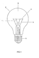
- Fig. 1 is an elevational view of an incandescent lamp according to the invention.
- the Incandescent lamp has within an outer glass bulb 2 an incandescent filament holder 1 and power supply 5 on. Between the power supply lines 5 is a held by the filament holder 1, e.g. double-wound W-wire 4 stretched as a luminous body.
- the power supply lines 5 are known per se Way melted into glass and led to the outside and inside a conventional screw 6 connected to its contacts, as shown in Fig. 1 with dashed lines.
- the glass bulb 2 in this first embodiment an internally applied electrostatic powder coating with cobalt aluminate pigments with spinel structure on which the yellow part of the emitted Light significantly reduced.
- it is 12 wt .-% of cobalt aluminates with spinel structure embedded in 88 Wt .-% fumed silica powder.
- Fig. 3 referenced.
- the Luminous efficiency significantly, in this example by about 20 %.
- the incandescent lamp according to the invention further provides a mixture of 80 vol.% Kr and 20 vol.% Of a mixture of 85 vol.% Ar and 15 vol.% N 2 as a gas filling.
- the filling pressure is 1000 mbar.
- this example is a conventional incandescent lamp with so-called A-piston and so-called E 27 socket, designed for effective Operating voltage of 230 V.
- Luminous efficacy can be increased by about 15%.
- the actual lamp power was 61.6 W and produced a luminous flux of 655 Im.
- the light bulb according to the invention thus has a refreshing and activating Effect on the human body and can the biorhythm influence. This is done by inhibiting melatonin formation an increased light emission in the range of about 450 nm the lamp because of the whiter and fresher light and the better Color rendering perceived as pleasant and comfortable.
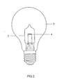
- FIG. 2 shows an alternative example in which the conventional filament 4 from Fig. 1 by a conventional high-voltage halogen burner was replaced. Illustrated clearly in Fig. 2 in the piston 2 of FIG. 1 a high-voltage halogen lamp 7 has been used, which has its own small Having piston for reducing the gas filling volume. It stays in the already explained with reference to FIG. 1 coating of the enveloping piston. 2 Here, the light output can be increased by the halogen technology. In addition, of course, further measures to increase the Luminous efficacy can be taken in comparison to a halogen bulb, at the expense of lifetime.
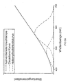
- the 3 a, b, c explain the principle of the invention with reference to three spectral Diagrams a, b and c, in which the radiation intensity of the lamps (in relative Units) as a function of the wavelength of the radiation in nm is applied.
- the first diagram a shows the solid curve the radiation intensity of a conventional and up to the invention Measures of the incandescent lamp of Fig. 1 corresponding 60 W bulb. This is a part of the thermal emission, the in the visible wavelength range.
- the curve is similar to a section from the Planckian radiation curve for the so-called black radiator, however For tungsten filament material shortwave radiation is something strengthened.
- the single dashed curve shows the product of this solid Curve with the relative sensitivity of the previously mentioned blue-sensitive Receptors of the human eye responsible for the control are responsible for melatonin production.
- the underlying sensitivity curve is recognizable in the blue spectral range.
- the maximal Sensitivity (100%) corresponds to the contact with the solid Curve.
- the details are in particular of the light / dark adaptation of the eye dependent and are not explained here in detail.
- the dashed So curve has only qualitative meaning.
- the dot-dashed curve shows the product of the solid curve the spectral brightness sensitivity of the human eye so on the ordinary eyesight.
- the brightness sensitivity has a maximum at about 555 nm, ie in the green range.
- An integral over the dot-dash curve would give the luminous flux of the lamp.
- the diagram a thus shows that a conventional light bulb due to the typical spectral distribution in thermal emission is only low circadian effective shares and relative thereto already greater brightness relevant Shares, but especially has a pronounced yellow and red area.
- the diagram b shows the curves from diagram a, where the solid Curve is dotted here.
- the solid line in the diagram b corresponds the incandescent emission according to the invention filtering. It can be seen that the filtering in the circadian effective range practically no spectral power filters away, but in the range between 500 and 700 nm clearly shows filter effect. On the relatively lower filter effect in the range between 700 and 800 nm is to be completed that one The aim is also that it is overall in a white impression remains, so the lamp is not colored. One recognizes that the dot-dashed Curve is lower, so the lamp is less bright.
- Diagram c shows qualitatively the diagram b, whereby however the solid Curve is vertically higher.
- the luminous flux loss has been taken into account.
- the diagram c show So the dotted and the solid line are essentially the same Luminous flux and thus essentially the same light output (at remained the same lamp power).
- the integral of dot-dashed curve over the visible range is about in both cases equal.
- the light bulb of the invention of FIG. 1 corresponds to this solid Line.
- the higher here compared to the diagrams a and b running dashed line shows that thereby the circadian spectral range absolutely grown.
Landscapes
- Radiation-Therapy Devices (AREA)
- Optical Filters (AREA)
Applications Claiming Priority (2)
| Application Number | Priority Date | Filing Date | Title |
|---|---|---|---|
| DE10358676A DE10358676A1 (de) | 2003-12-12 | 2003-12-12 | Glühlampe mit aktivierender Wirkung |
| DE10358676 | 2003-12-12 |
Publications (2)
| Publication Number | Publication Date |
|---|---|
| EP1564790A2 true EP1564790A2 (fr) | 2005-08-17 |
| EP1564790A3 EP1564790A3 (fr) | 2008-05-14 |
Family
ID=34638701
Family Applications (1)
| Application Number | Title | Priority Date | Filing Date |
|---|---|---|---|
| EP04028443A Withdrawn EP1564790A3 (fr) | 2003-12-12 | 2004-12-01 | Lampe à incandescence avec filtre coloré |
Country Status (4)
| Country | Link |
|---|---|
| US (1) | US20050127836A1 (fr) |
| EP (1) | EP1564790A3 (fr) |
| CA (1) | CA2489748A1 (fr) |
| DE (1) | DE10358676A1 (fr) |
Families Citing this family (5)
| Publication number | Priority date | Publication date | Assignee | Title |
|---|---|---|---|---|
| DE102005012487A1 (de) * | 2005-03-16 | 2006-09-21 | Patent-Treuhand-Gesellschaft für elektrische Glühlampen mbH | Halogenglühlampe |
| JP2010500077A (ja) * | 2006-08-07 | 2010-01-07 | コーニンクレッカ フィリップス エレクトロニクス エヌ ヴィ | 光生物学的状態に影響を与えるためのシステムおよび方法 |
| US20090085463A1 (en) * | 2007-09-28 | 2009-04-02 | General Electric Company | Thermo-optically functional compositions, systems and methods of making |
| US11672074B2 (en) | 2019-07-11 | 2023-06-06 | Lockheed Martin Corporation | Shielding structures in plasma environment |
| CN218298703U (zh) * | 2022-04-19 | 2023-01-13 | 京东方科技集团股份有限公司 | 灯条组件、背光模组及显示装置 |
Family Cites Families (10)
| Publication number | Priority date | Publication date | Assignee | Title |
|---|---|---|---|---|
| DE8010444U1 (de) * | 1980-04-16 | 1981-01-15 | Patent-Treuhand-Gesellschaft Fuer Elektrische Gluehlampen Mbh, 8000 Muenchen | Quecksilberdampf-hochdruckentladungslampe mit aussenkolben |
| US4633127A (en) * | 1983-02-10 | 1986-12-30 | U.S. Philips Corp. | Electric lamp having a strongly colored lamp envelope |
| JPH0628151B2 (ja) * | 1988-02-10 | 1994-04-13 | 東芝ライテック株式会社 | ハロゲン電球 |
| JP2626061B2 (ja) * | 1989-06-17 | 1997-07-02 | 東芝ライテック株式会社 | 白熱電球 |
| DE4120797A1 (de) * | 1991-06-24 | 1993-01-07 | Patent Treuhand Ges Fuer Elektrische Gluehlampen Mbh | Elektrische lampe |
| WO2001024224A1 (fr) * | 1999-09-30 | 2001-04-05 | Koninklijke Philips Electronics N.V. | Lampe electrique |
| DE10040887A1 (de) * | 2000-08-18 | 2001-08-30 | Philips Corp Intellectual Pty | Halogen-Glühlampe für Kraftfahrzeuge |
| KR20040039355A (ko) * | 2001-09-13 | 2004-05-10 | 코닌클리즈케 필립스 일렉트로닉스 엔.브이. | 전기 램프, 램프관 및 그 제조 방법 |
| US6731051B2 (en) * | 2002-04-22 | 2004-05-04 | Osram Sylvania Inc. | Blue incandescent appliance lamp |
| US6670768B1 (en) * | 2002-07-22 | 2003-12-30 | Osram Sylvania Inc. | Blue incandescent general purpose lamp |
-
2003
- 2003-12-12 DE DE10358676A patent/DE10358676A1/de not_active Withdrawn
-
2004
- 2004-12-01 EP EP04028443A patent/EP1564790A3/fr not_active Withdrawn
- 2004-12-10 CA CA002489748A patent/CA2489748A1/fr not_active Abandoned
- 2004-12-13 US US11/009,140 patent/US20050127836A1/en not_active Abandoned
Also Published As
| Publication number | Publication date |
|---|---|
| US20050127836A1 (en) | 2005-06-16 |
| CA2489748A1 (fr) | 2005-06-12 |
| EP1564790A3 (fr) | 2008-05-14 |
| DE10358676A1 (de) | 2005-07-07 |
Similar Documents
| Publication | Publication Date | Title |
|---|---|---|
| DE2812120A1 (de) | Hochdruck-quecksilberdampf-entladungslampe | |
| DD248223A5 (de) | Niederdruckquecksilberdampfentladungslampe | |
| EP1735405B1 (fr) | Composition luminescente pour lampe a decharge basse pression a temperature de couleur tres elevee | |
| DE69010258T2 (de) | Niederdruckquecksilberdampfentladungslampe. | |
| DE68911587T2 (de) | Hochdruckmetallhalogenidentladungslampe. | |
| EP2260505A1 (fr) | Lampe à décharge à basse pression pour influencer la production de mélatonine propre au corps | |
| DE69920534T2 (de) | Entladungslampe und Leuchte | |
| DE60311431T2 (de) | Lampe für kraftfahrzeugscheinwerfer mit abblendlicht | |
| DE3938827A1 (de) | Elektrodenlose entladungslampe | |
| DE2624898A1 (de) | Quecksilberdampf-lampe | |
| EP2102892A2 (fr) | Lampe avec une ampoule a revetement partiel | |
| DE10358676A1 (de) | Glühlampe mit aktivierender Wirkung | |
| EP1651906B1 (fr) | Lampe comprenant au moins deux sources de lumiere | |
| DE2606740C3 (de) | Leuchtstoffschicht für Hochdruck-Quecksilberdampflampen | |
| EP1351277A2 (fr) | Charge aux halogénures métalliques et lampe correspondante | |
| DE2841545A1 (de) | Leuchtendes erdalkaliphosphat | |
| DE29906717U1 (de) | Leuchte | |
| DE69711734T2 (de) | Glühlampe mit Reflektor mit sonnenähnlichem Emissionsspektrum | |
| EP0925602A2 (fr) | Lampe a decharge aux halogenures de metal presentant une longue duree de vie | |
| DE1789163C2 (de) | Hochdrucklampe | |
| WO2020187840A1 (fr) | Module del | |
| EP3840068A1 (fr) | Module à del émettant de la lumière blanche | |
| EP3843611A1 (fr) | Émetteur large bande pour rayonnement électromagnétique | |
| DE102013008123B4 (de) | Lampe auf LED-Basis für Innenraumbeleuchtung | |
| DE2659609C2 (fr) |
Legal Events
| Date | Code | Title | Description |
|---|---|---|---|
| PUAI | Public reference made under article 153(3) epc to a published international application that has entered the european phase |
Free format text: ORIGINAL CODE: 0009012 |
|
| AK | Designated contracting states |
Kind code of ref document: A2 Designated state(s): AT BE BG CH CY CZ DE DK EE ES FI FR GB GR HU IE IS IT LI LT LU MC NL PL PT RO SE SI SK TR |
|
| AX | Request for extension of the european patent |
Extension state: AL BA HR LV MK YU |
|
| PUAL | Search report despatched |
Free format text: ORIGINAL CODE: 0009013 |
|
| AK | Designated contracting states |
Kind code of ref document: A3 Designated state(s): AT BE BG CH CY CZ DE DK EE ES FI FR GB GR HU IE IS IT LI LT LU MC NL PL PT RO SE SI SK TR |
|
| AX | Request for extension of the european patent |
Extension state: AL BA HR LV MK YU |
|
| 17P | Request for examination filed |
Effective date: 20080521 |
|
| 17Q | First examination report despatched |
Effective date: 20080702 |
|
| AKX | Designation fees paid |
Designated state(s): BE DE FR GB IT NL |
|
| STAA | Information on the status of an ep patent application or granted ep patent |
Free format text: STATUS: THE APPLICATION IS DEEMED TO BE WITHDRAWN |
|
| 18D | Application deemed to be withdrawn |
Effective date: 20081113 |