EP1564848B1 - Dispositif d'installation avec interface enfichable codable et module supplémentaire correspondant - Google Patents
Dispositif d'installation avec interface enfichable codable et module supplémentaire correspondant Download PDFInfo
- Publication number
- EP1564848B1 EP1564848B1 EP05100592.4A EP05100592A EP1564848B1 EP 1564848 B1 EP1564848 B1 EP 1564848B1 EP 05100592 A EP05100592 A EP 05100592A EP 1564848 B1 EP1564848 B1 EP 1564848B1
- Authority
- EP
- European Patent Office
- Prior art keywords
- module
- installation device
- additional module
- additional
- connection
- Prior art date
- Legal status (The legal status is an assumption and is not a legal conclusion. Google has not performed a legal analysis and makes no representation as to the accuracy of the status listed.)
- Expired - Lifetime
Links
Images



Classifications
-
- H—ELECTRICITY
- H05—ELECTRIC TECHNIQUES NOT OTHERWISE PROVIDED FOR
- H05K—PRINTED CIRCUITS; CASINGS OR CONSTRUCTIONAL DETAILS OF ELECTRIC APPARATUS; MANUFACTURE OF ASSEMBLAGES OF ELECTRICAL COMPONENTS
- H05K7/00—Constructional details common to different types of electric apparatus
- H05K7/14—Mounting supporting structure in casing or on frame or rack
- H05K7/1462—Mounting supporting structure in casing or on frame or rack for programmable logic controllers [PLC] for automation or industrial process control
- H05K7/1468—Mechanical features of input/output (I/O) modules
- H05K7/1469—Terminal blocks for connecting sensors
-
- H—ELECTRICITY
- H01—ELECTRIC ELEMENTS
- H01R—ELECTRICALLY-CONDUCTIVE CONNECTIONS; STRUCTURAL ASSOCIATIONS OF A PLURALITY OF MUTUALLY-INSULATED ELECTRICAL CONNECTING ELEMENTS; COUPLING DEVICES; CURRENT COLLECTORS
- H01R13/00—Details of coupling devices of the kinds covered by groups H01R12/70 or H01R24/00 - H01R33/00
- H01R13/64—Means for preventing incorrect coupling
-
- H—ELECTRICITY
- H01—ELECTRIC ELEMENTS
- H01R—ELECTRICALLY-CONDUCTIVE CONNECTIONS; STRUCTURAL ASSOCIATIONS OF A PLURALITY OF MUTUALLY-INSULATED ELECTRICAL CONNECTING ELEMENTS; COUPLING DEVICES; CURRENT COLLECTORS
- H01R9/00—Structural associations of a plurality of mutually-insulated electrical connecting elements, e.g. terminal strips or terminal blocks; Terminals or binding posts mounted upon a base or in a case; Bases therefor
- H01R9/22—Bases, e.g. strip, block, panel
- H01R9/24—Terminal blocks
- H01R9/2475—Means facilitating correct wiring, e.g. marking plates, identification tags
Definitions
- the present invention relates to an additional module for attachment to the installation device with a device interface including a fastening device with which the additional module can be attached to the installation device, and a module interface including a module mounting device with which a further additional module can be attached to the present additional module.
- connection modules to which cables can be fastened by means of screw, spring-loaded or insulation displacement technology
- peg-shaped coding on the installation device and corresponding Gegenkodierstoff be used on the connection module to ensure a module-specific assignment.
- latching means are provided on the corresponding module slots and counter-locking means on the connection modules.
- the DE 196 50 988 A1 relates to electrical terminal blocks, wherein the terminals of the terminal blocks additional terminals are docked, which automatically contact a docking end contact of the terminal, which in turn is connected via a terminal-internal line with the built-in or plugged electronics.
- connection modules can be arranged on the connection modules.
- Corresponding coding means in the form of recesses for a module-specific assignment are provided for each connection module.
- the Jacobkodierstoff to the connection modules are designed as angular elements.
- the object of the present invention is therefore to propose an additional module for attachment to an installation device, which can be mounted on a module place or several module places without confusion with simply formed contours.
- an additional module for attachment to an installation device with a device interface including a fastening device, with which the additional module can be attached to the installation device, and first coding, which at the device interface are arranged so that the additional module is attachable to the installation device only if the installation device has corresponding Gegenkodierstoff, wherein the first coding means are part of the fastening device and a module interface including a module fastening device with which a further additional module can be attached to the present additional module, and Modulkodierstoff, which are arranged on the module interface, has, so that the additional module is attachable to the present additional module only if the additional module further module corresponding Jacobkodierstoff, wherein the fastening means has at least one, in cross-section L-shaped projection, so that the Additional module by two mutually orthogonal motion operations on the installation device can be fastened, wherein according to the first of the movement processes, a first fixation takes place and the second of the movement processes, the additional module is brought
- the fastening device of the installation device on an L-shaped recess so that the additional module, which has an L-shaped, orthogonal to the L-shape of the recess projection, can be fastened by two mutually orthogonal motion operations on the installation device. It is particularly advantageous if a dimension or position of the L-shaped recess is selected in dependence on the coding of the first coding means. In this way, a very easy to be designed fastening and coding can be realized, and it must not be provided in addition to the fasteners recesses or projections for coding on the installation device or additional module. This is a contribution to simplification the contour of the installation device and additional module made.
- the present additional module has a module interface including a module fastening device, with which the additional module can be fastened to the present additional module, and module coding, which are arranged on the module interface, so that the additional module is attachable to the present additional module only if the other Add-on module according to the module has Gegenkodierstoff. It is particularly advantageous in this case if, in turn, the module coding means are part of the module fastening device.
- additional modules can be applied and plugged in easily and without confusion even on additional module.
- an interface to installation devices for connection modules with different connection technologies can be advantageously realized, taking into account the connection to higher-level control systems by control modules. Furthermore, it is possible to attach the connection modules and the control modules without confusion to the installation devices. In particular, it is possible to connect a connection module or a detachable terminal and / or a control module for a connection to a higher-level controller to a compact branch, which represents an installation device.
- the connection of fastening and coding means brings a significant simplification of the module interface of the installation device or the module to be attached.
- the additional module preferably has a locking device for locking the additional module to the installation device.
- the locking device may have a latching hook. This makes it possible to lock from connection modules and control modules to the installation devices to prevent unintentional loosening with a small footprint.
- the installation device may further comprise a plurality of said module interfaces.
- control modules can be coupled to the installation device, but it is also possible to provide the control modules on one side of the installation device and the connection modules on another side.
- second encoding means independent of the first coding means are arranged on the module interface for interaction with corresponding second counter-coding means on the additional module to be attached.
- the second coding means may comprise at least one pin or at least one corresponding recess at a predetermined location on the module interface. This means that different coding means, with and without fastening or guiding function, can be combined with one another as desired.
- the additional module can be designed as a connection module or control module.
- the control module can then be realized in particular as a start module or expansion module.
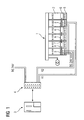
- FIG. 1 shows a power distribution system 1 to which a plurality of installation devices 2 are connected.
- PLC higher-level control
- K1 or K2 one or more installation devices are controlled via plugged control modules or the switching states of the installation devices 2 the higher-level controller 3 reported back.
- the control modules which can be implemented as start modules 5 or expansion modules 6, each contain an electronic unit for data transmission. With connection plugs 7, the control modules 5, 6 can be connected to each other.
- the starter modules 5 require terminals for For example, a power supply and the control or feedback channel K1 or K2. Since the supply voltage and the control signals are forwarded via a connector 7 from the start module 5 to the first expansion module 6 or between the other expansion modules 6, no terminals are necessary in the extension modules 6 in this form.
- connection module 8 For various lines to be connected each installation device is additionally equipped with a connection module 8 in the present example. For the sake of clarity, however, connection cables that open in the connection modules are in FIG. 1 not shown.
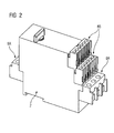
- FIG. 2 is a motor starter, a typical installation device 2, shown in perspective.
- connection modules 8 are mounted on the installation device 2.
- the power connections 8A take place via a connection module on each side of the installation device and the control connections via connection modules 8B advantageously on one side of the installation device 2, as also in FIG. 2 is reproduced.
- connection modules can basically be implemented in any connection technology be.
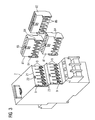
- the two connection modules 81 in the embodiment are shown in screw technology and the connection module 82 in the design in spring-loaded technology.
- connection wires are screwed into the connection modules.
- connection module 82 which is designed in Federzugtechnik to clamp terminals in a likewise known manner.
- the attachment of the modules to the installation devices is independent of the connection technology used.
- the installation device 2 has at its lateral boundary walls L- or angular recesses 9.
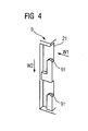
- a recess 9 is in FIG. 4 shown enlarged.
- the recesses 9 result in the assembly of a connection module 8 a first geometric fixation to the installation device 2.
- This first fixation takes place in accordance with a first movement W1 whose direction in FIG. 4 is shown with an arrow, and with which the module to be fixed is guided to the installation device 2 and in the recess 9.
- This fixation is supported by phases or curves 91 on the recesses 9.
- connection module Via a second movement W2, whose direction is in FIG. 4 is also shown with an arrow, the connection module is brought along the end-side guide wall 21 of the installation device in its final position.
- a locking hook 83 locks in a recess 22 on the end face of the installation device 2 (cf. FIG. 3 ).
- the locking or locking hooks can be brought out of its lock in the recess 22.
- the electrical connections to the respective module interfaces are made via contacts 23. These tower in the present example on the installation device 2 to the outside and engage in recesses 86 with corresponding mating contacts in the connection module.
- each module has on both sides corresponding bracket-like projections 84. These have in partial sections in a cross section perpendicular to the direction of movement W2 an L-shaped configuration. In the assembled state then engages the remote from the module leg of the L-shaped projection 84 into the recess 9 of the installation device.
- connection modules for example the in FIG. 5 marked slots SA and SB, on the installation device 2 can be done via appropriate coding.
- the angular recesses 9 on the installation device 2 and also the clip-like projections 84 on the connection modules are designed for this purpose in various geometrical dimensions. Accordingly, a recess 9 A is provided at the slot SA, which according to the left drawing of FIG. 5 has two vertical openings 92 and 93 with the dimensions A1 and A2.
- connection module for the slot A accordingly has a mating contour or a clip-like projection 84A with two angled legs 841 and 842, the vertical dimension of which is A1-S or A2-S.
- S corresponds to the clearance necessary for inserting the legs 841 and 842 into the frontal openings 92 and 93 of the recess 9 or 9A. Due to the different dimensions, a coding is created on the fastening device for the connection modules on the installation device 2 in order to avoid the insertion of wrong modules.
- the L-shaped recess 9 can also be formed in the connection module 8 and the corresponding counter contour 84 in the installation device 2. The same applies to the following coding.
- FIG. 6 be provided at the two components to be connected 2 and 8 pins and corresponding recesses at certain locations or in a certain size.
- FIG. 6 is shown at the bottom left, provided for the module MA pins 851 and 852 at other locations as pins 853 and 854 on the module MB.
- the pins 851 to 854 matching recesses 251 to 254, which have elongated shape, so that the insertion movement in the direction W2 remains possible.
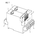
- FIG. 7 is an installation device, eg. As a motor starter with mounted control modules for a connection to an automation system FIG. 1 shown.
- control modules 5, 6 are also connected to the two combined installation devices 2.
- a starter module 5 is plugged onto one of the installation devices 2 and an expansion module 6 is plugged onto the other.
- These two control modules are, as already in FIG. 1 indicated, coupled with a connector 7. Since the start module 5 requires connections, a separate connection module 8 is plugged into the start module 5.
- the same fastening and coding devices can be used as for the interface between the start module 5 and the installation device. 2
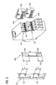
- FIG. 8 is also the installation device combination of FIG. 7 shown, but the drive modules 5 and 6 including the one connection module 8 were removed from the installation devices.
- the removed control modules 5, 6 are shown rotated, so that their connection side or module interface is visible. Accordingly, the locking hooks 83 can be seen clearly on the installation devices 2, for example, the angular recesses 9 and the Anêtmodulen 5, 6.
- FIG. 9 are the on the installation device combination of FIG. 7 plugged control modules 5 and 6 shown enlarged.
- the connection module 8 is removed in this figure and played rotated. It has, as already mentioned, the same connection interface as the control modules 5 and 6 or the connection modules 81, 82 of FIG FIG. 3 , Accordingly, it has a locking hook 83 and pins 851 and 852 for the additional coding.
- the angular recesses 9 and the recesses 251 and 252 can be seen at the module slot for the connection module 8 on the start module 5.
- the recesses 9 are not only for attachment, but according to the invention also for coding.
Landscapes
- Engineering & Computer Science (AREA)
- Automation & Control Theory (AREA)
- Microelectronics & Electronic Packaging (AREA)
- Casings For Electric Apparatus (AREA)
Claims (7)
- Combinaison d'appareils d'installation, ayant un appareil (2) d'installation, un module (5) supplémentaire à mettre sur l'appareil (2) d'installation, et un autre module (8) supplémentaire qui peut être mis sur le module (5) supplémentaire, le module (5) supplémentaire comprenant :- une interface (SA, SB) d'appareil, y compris un dispositif (84) de fixation, par lequel le module (5, 6) supplémentaire peut être fixé sur l'appareil (2) d'installation,- des premiers moyens (841, 842) de codage, qui sont disposés sur l'interface (SA, SB) d'appareil, de manière à ne pouvoir mettre le module (5, 6) supplémentaire sur l'appareil (2) d'installation que si l'appareil (2) d'installation a des moyens (92, 93) antagonistes de codage correspondants,- dans laquelle les premiers moyens (841, 842) de codage font partie du dispositif (84) de fixation et- une interface (SA, SB) de module, y compris un dispositif (9) de fixation de module, par lequel l'autre module (8) supplémentaire peut être fixé au module (5) supplémentaire présent, et des moyens (92, 93) de codage de module, qui sont disposés sur l'interface (SA, SB) de module, de manière à ce que le module (8) supplémentaire ne puisse être mis sur le module (5) supplémentaire présent que si l'autre module (8) supplémentaire a des moyens (841, 842) antagonistes de codage de module correspondants
caractérisé en ce que- le dispositif (84) de fixation a au moins une saillie (841, 842) de section transversale en forme de L, de manière à pouvoir fixer le module (5) supplémentaire par deux opérations (W1, W2) de déplacement orthogonales entre elles, sur un évidement (9) en forme de L de l'appareil (2) d'installation, une première immobilisation s'effectuant conformément à la première des opérations (W1) de déplacement et le module (5) supplémentaire étant mis dans la position définitive par la deuxième des opérations (W2) de déplacement,- le dispositif (9) de fixation de module a au moins un évidement (92, 93) en forme de L, de manière à pouvoir fixer une saillie en forme de L en section transversale de l'autre module (8) supplémentaire par deux opérations (W1, W2) de déplacement orthogonales entre elles sur l'évidement en forme de L du module (5) supplémentaire présent, une première immobilisation s'effectuant conformément à la première des opérations (W1) de déplacement, et l'autre module (8) supplémentaire étant mis dans une position définitive par la deuxième des opérations (W2) de déplacement. - Combinaison d'appareil d'installation suivant la revendication 1, dans laquelle le module (5) supplémentaire est constitué en module (8) de raccordement ou en module (5, 6) de commande.
- Combinaison d'appareil d'installation suivant la revendication 1 ou 2, dans laquelle le module (5) supplémentaire a un dispositif de verrouillage pour verrouiller le module supplémentaire sur l'appareil (2) d'installation.
- Combinaison d'appareil d'installation suivant la revendication 3, dans laquelle le dispositif de verrouillage a un crochet (83) de verrouillage.
- Combinaison d'appareil d'installation suivant l'une des revendications 1 à 4, dans laquelle les moyens (92, 93) de codage de module font partie du dispositif (9) de fixation de module.
- Combinaison d'appareil d'installation suivant l'une des revendications 1 à 5, dans laquelle des deuxièmes moyens (251, 252) de codage de module, indépendants des premiers moyens (92, 93) de codage de module, sont disposés sur l'interface (SA, SB) de module, pour coopérer avec des deuxièmes moyens (851, 852) de codage antagonistes de module sur l'autre module (8) supplémentaire à mettre.
- Combinaison d'appareil d'installation suivant la revendication 6, dans laquelle les deuxièmes moyens (251, 252) de codage de module comprennent au moins un tourillon ou un évidement correspondant en un emplacement déterminé à l'avance de l'interface de module.
Applications Claiming Priority (2)
| Application Number | Priority Date | Filing Date | Title |
|---|---|---|---|
| DE102004007423 | 2004-02-16 | ||
| DE102004007423 | 2004-02-16 |
Publications (2)
| Publication Number | Publication Date |
|---|---|
| EP1564848A1 EP1564848A1 (fr) | 2005-08-17 |
| EP1564848B1 true EP1564848B1 (fr) | 2013-10-16 |
Family
ID=34684066
Family Applications (1)
| Application Number | Title | Priority Date | Filing Date |
|---|---|---|---|
| EP05100592.4A Expired - Lifetime EP1564848B1 (fr) | 2004-02-16 | 2005-01-28 | Dispositif d'installation avec interface enfichable codable et module supplémentaire correspondant |
Country Status (1)
| Country | Link |
|---|---|
| EP (1) | EP1564848B1 (fr) |
Families Citing this family (8)
| Publication number | Priority date | Publication date | Assignee | Title |
|---|---|---|---|---|
| WO2008028433A1 (fr) * | 2006-09-08 | 2008-03-13 | Siemens Aktiengesellschaft | Module complémentaire électrique pour un appareillage d'installation, combinaison du module complémentaire avec l'appareillage d'installation et jeu de modules complémentaires |
| DE112006004120A5 (de) * | 2006-09-08 | 2009-08-13 | Siemens Aktiengesellschaft | Zusatzmodul zur Montage an ein Installationsgerät sowie Kombination aus dem Zusatzmodul mit dem Installationsgerät |
| EP2256868A1 (fr) * | 2009-05-27 | 2010-12-01 | Siemens Aktiengesellschaft | Appareil d'automatisation doté d'un module terminal |
| DE102012010391B4 (de) * | 2011-06-17 | 2025-08-21 | Phoenix Contact Gmbh & Co. Kg | Elektrisches Verbindungsmodul |
| DE102012204854A1 (de) * | 2012-03-27 | 2013-10-02 | Siemens Aktiengesellschaft | Modulares Installationsgerät |
| DE102014101528A1 (de) * | 2014-02-07 | 2015-08-13 | Phoenix Contact Gmbh & Co. Kg | Wabenbaustein und Rangierwabe |
| JP6962309B2 (ja) * | 2018-12-14 | 2021-11-05 | オムロン株式会社 | 端子台および端子台セット |
| EP4487422A4 (fr) * | 2022-03-04 | 2026-01-14 | Honeywell Int Inc | Bloc de borne auxiliaire destiné à être utilisé avec un module électronique |
Citations (2)
| Publication number | Priority date | Publication date | Assignee | Title |
|---|---|---|---|---|
| EP0774768A1 (fr) * | 1995-11-14 | 1997-05-21 | Eaton Corporation | Système de commande modulaire pour contacteur |
| US5697806A (en) * | 1995-07-06 | 1997-12-16 | The Whitaker Corporation | Stackable electrical connector |
Family Cites Families (7)
| Publication number | Priority date | Publication date | Assignee | Title |
|---|---|---|---|---|
| DE7138560U (de) * | 1971-10-12 | 1973-05-17 | Siemens Ag | Gehäuse für ein elektrisches Gerät |
| DE19650988C2 (de) | 1996-11-28 | 2003-06-26 | Wago Verwaltungs Gmbh | Reihenklemme mit eingebauter oder aufsteckbarer Elektronik |
| DE19964156B4 (de) | 1999-01-25 | 2004-07-15 | Weidmüller Interface Gmbh & Co. | Elektrisches Gerät |
| FR2805094B1 (fr) | 2000-02-14 | 2002-03-29 | Schneider Electric Ind Sa | Ensemble de depart-moteur |
| DE10119458B4 (de) * | 2001-04-20 | 2004-08-19 | Siemens Ag | Schaltgeräteeinheit für einen Verbraucher, insbesondere Motorstarter |
| DE10301003B3 (de) | 2003-01-13 | 2004-09-30 | Siemens Ag | Modulares Installationsgerät |
| DE10301004B3 (de) | 2003-01-13 | 2004-10-07 | Siemens Ag | Modulares Installationsgerät |
-
2005
- 2005-01-28 EP EP05100592.4A patent/EP1564848B1/fr not_active Expired - Lifetime
Patent Citations (2)
| Publication number | Priority date | Publication date | Assignee | Title |
|---|---|---|---|---|
| US5697806A (en) * | 1995-07-06 | 1997-12-16 | The Whitaker Corporation | Stackable electrical connector |
| EP0774768A1 (fr) * | 1995-11-14 | 1997-05-21 | Eaton Corporation | Système de commande modulaire pour contacteur |
Also Published As
| Publication number | Publication date |
|---|---|
| EP1564848A1 (fr) | 2005-08-17 |
Similar Documents
| Publication | Publication Date | Title |
|---|---|---|
| EP2946644B1 (fr) | Ensemble doté d'un module et d'un dispositif électronique | |
| EP3345255B1 (fr) | Système constitué d'un cadre modulaire de connecteur enfichable et d'éléments adaptateurs | |
| WO2019025139A1 (fr) | Unité de prise pour agencement d'appareils disposés en série | |
| EP2086077A2 (fr) | Système de montage pour composants électriques et/ou mécaniques | |
| EP3480898A1 (fr) | Cadre de support modulaire pour connecteur enfichable | |
| DE2534775B2 (de) | Anordnung bei flachbaugruppen mit frontsteckern | |
| EP2497169A2 (fr) | Agencement de montage pour appareils électriques | |
| EP1564848B1 (fr) | Dispositif d'installation avec interface enfichable codable et module supplémentaire correspondant | |
| DE19627481C2 (de) | Elektrische Schalt- und Sicherungsvorrichtung | |
| EP1630917B1 (fr) | Système de montage et de connexion pour appareils électriques | |
| EP1520330B1 (fr) | Support pour boitier de modules | |
| EP1595311B1 (fr) | Raccordement a fiches | |
| DE4428687C1 (de) | Baugruppe eines elektrischen Geräts | |
| DE19610037C2 (de) | Baugruppenträger | |
| DE10013346C2 (de) | Durchführungsadapter und Steckverbinder für einen Durchführungsadapter | |
| EP2059976A1 (fr) | Module complementaire electrique pour un appareillage d'installation, combinaison du module complementaire avec l'appareillage d'installation et jeu de modules complementaires | |
| DE202016104346U1 (de) | Flexibles erweiterbares Automatisierungsgerät | |
| DE102019134828A1 (de) | Befestigungssystem und Schaltschrank | |
| DE19700057C2 (de) | Datenschiene für den Europäischen Installationsbus (EIB) | |
| EP1401062A1 (fr) | Système de contact à fiche pour appareils ménagers | |
| EP4305656B1 (fr) | Disposition de boîtiers, procédé de montage de la disposition de boîtiers et boîtiers | |
| DE3710708C2 (fr) | ||
| EP2262062B1 (fr) | Connecteur à fiches | |
| WO2008028434A1 (fr) | Module complémentaire destiné à être monté sur un appareillage d'installation et combinaison du module complémentaire avec l'appareillage d'installation | |
| DE19902811C1 (de) | Kodiervorrichtung und Kodierverfahren zur Kodierung eines elektrischen Gerätes |
Legal Events
| Date | Code | Title | Description |
|---|---|---|---|
| PUAI | Public reference made under article 153(3) epc to a published international application that has entered the european phase |
Free format text: ORIGINAL CODE: 0009012 |
|
| AK | Designated contracting states |
Kind code of ref document: A1 Designated state(s): AT BE BG CH CY CZ DE DK EE ES FI FR GB GR HU IE IS IT LI LT LU MC NL PL PT RO SE SI SK TR |
|
| AX | Request for extension of the european patent |
Extension state: AL BA HR LV MK YU |
|
| 17P | Request for examination filed |
Effective date: 20050922 |
|
| AKX | Designation fees paid |
Designated state(s): DE FR IT SE |
|
| RAP1 | Party data changed (applicant data changed or rights of an application transferred) |
Owner name: SIEMENS AKTIENGESELLSCHAFT |
|
| GRAP | Despatch of communication of intention to grant a patent |
Free format text: ORIGINAL CODE: EPIDOSNIGR1 |
|
| INTG | Intention to grant announced |
Effective date: 20130508 |
|
| GRAS | Grant fee paid |
Free format text: ORIGINAL CODE: EPIDOSNIGR3 |
|
| GRAA | (expected) grant |
Free format text: ORIGINAL CODE: 0009210 |
|
| AK | Designated contracting states |
Kind code of ref document: B1 Designated state(s): DE FR IT SE |
|
| REG | Reference to a national code |
Ref country code: DE Ref legal event code: R096 Ref document number: 502005014030 Country of ref document: DE Effective date: 20131212 |
|
| REG | Reference to a national code |
Ref country code: SE Ref legal event code: TRGR |
|
| RAP2 | Party data changed (patent owner data changed or rights of a patent transferred) |
Owner name: SIEMENS AKTIENGESELLSCHAFT |
|
| REG | Reference to a national code |
Ref country code: DE Ref legal event code: R097 Ref document number: 502005014030 Country of ref document: DE |
|
| PLBE | No opposition filed within time limit |
Free format text: ORIGINAL CODE: 0009261 |
|
| STAA | Information on the status of an ep patent application or granted ep patent |
Free format text: STATUS: NO OPPOSITION FILED WITHIN TIME LIMIT |
|
| 26N | No opposition filed |
Effective date: 20140717 |
|
| REG | Reference to a national code |
Ref country code: DE Ref legal event code: R097 Ref document number: 502005014030 Country of ref document: DE Effective date: 20140717 |
|
| REG | Reference to a national code |
Ref country code: FR Ref legal event code: PLFP Year of fee payment: 12 |
|
| REG | Reference to a national code |
Ref country code: FR Ref legal event code: PLFP Year of fee payment: 13 |
|
| PGFP | Annual fee paid to national office [announced via postgrant information from national office to epo] |
Ref country code: DE Payment date: 20170320 Year of fee payment: 13 Ref country code: FR Payment date: 20170117 Year of fee payment: 13 Ref country code: SE Payment date: 20170105 Year of fee payment: 13 |
|
| PGFP | Annual fee paid to national office [announced via postgrant information from national office to epo] |
Ref country code: IT Payment date: 20170127 Year of fee payment: 13 |
|
| REG | Reference to a national code |
Ref country code: DE Ref legal event code: R119 Ref document number: 502005014030 Country of ref document: DE |
|
| REG | Reference to a national code |
Ref country code: SE Ref legal event code: EUG |
|
| PG25 | Lapsed in a contracting state [announced via postgrant information from national office to epo] |
Ref country code: SE Free format text: LAPSE BECAUSE OF NON-PAYMENT OF DUE FEES Effective date: 20180129 Ref country code: DE Free format text: LAPSE BECAUSE OF NON-PAYMENT OF DUE FEES Effective date: 20180801 Ref country code: FR Free format text: LAPSE BECAUSE OF NON-PAYMENT OF DUE FEES Effective date: 20180131 |
|
| REG | Reference to a national code |
Ref country code: FR Ref legal event code: ST Effective date: 20180928 |
|
| PG25 | Lapsed in a contracting state [announced via postgrant information from national office to epo] |
Ref country code: IT Free format text: LAPSE BECAUSE OF NON-PAYMENT OF DUE FEES Effective date: 20180128 |