EP1564849A1 - Drehverbinder - Google Patents
Drehverbinder Download PDFInfo
- Publication number
- EP1564849A1 EP1564849A1 EP05002908A EP05002908A EP1564849A1 EP 1564849 A1 EP1564849 A1 EP 1564849A1 EP 05002908 A EP05002908 A EP 05002908A EP 05002908 A EP05002908 A EP 05002908A EP 1564849 A1 EP1564849 A1 EP 1564849A1
- Authority
- EP
- European Patent Office
- Prior art keywords
- flat cable
- holder
- tube
- rotor
- outer tube
- Prior art date
- Legal status (The legal status is an assumption and is not a legal conclusion. Google has not performed a legal analysis and makes no representation as to the accuracy of the status listed.)
- Withdrawn
Links
- 238000004804 winding Methods 0.000 claims abstract description 34
- 230000000452 restraining effect Effects 0.000 claims description 34
- 210000002105 tongue Anatomy 0.000 claims description 33
- 230000000149 penetrating effect Effects 0.000 claims description 21
- 230000008878 coupling Effects 0.000 claims description 15
- 238000010168 coupling process Methods 0.000 claims description 15
- 238000005859 coupling reaction Methods 0.000 claims description 15
- 230000001105 regulatory effect Effects 0.000 claims description 9
- 230000000295 complement effect Effects 0.000 claims description 4
- 230000003247 decreasing effect Effects 0.000 description 50
- 229920003002 synthetic resin Polymers 0.000 description 21
- 239000000057 synthetic resin Substances 0.000 description 21
- 230000007704 transition Effects 0.000 description 16
- 230000009467 reduction Effects 0.000 description 9
- 230000005540 biological transmission Effects 0.000 description 2
- 230000008859 change Effects 0.000 description 2
- 239000004020 conductor Substances 0.000 description 2
- 230000000694 effects Effects 0.000 description 2
- WABPQHHGFIMREM-UHFFFAOYSA-N lead(0) Chemical compound [Pb] WABPQHHGFIMREM-UHFFFAOYSA-N 0.000 description 2
- 229920001343 polytetrafluoroethylene Polymers 0.000 description 2
- 239000004810 polytetrafluoroethylene Substances 0.000 description 2
- 230000033228 biological regulation Effects 0.000 description 1
- 239000004519 grease Substances 0.000 description 1
- 238000009413 insulation Methods 0.000 description 1
- 239000000314 lubricant Substances 0.000 description 1
- 239000000463 material Substances 0.000 description 1
- 230000004048 modification Effects 0.000 description 1
- 238000012986 modification Methods 0.000 description 1
- -1 polytetrafluoroethylene Polymers 0.000 description 1
- 229920005989 resin Polymers 0.000 description 1
- 239000011347 resin Substances 0.000 description 1
- 238000004904 shortening Methods 0.000 description 1
- 230000009466 transformation Effects 0.000 description 1
Images


Classifications
-
- E—FIXED CONSTRUCTIONS
- E05—LOCKS; KEYS; WINDOW OR DOOR FITTINGS; SAFES
- E05D—HINGES OR SUSPENSION DEVICES FOR DOORS, WINDOWS OR WINGS
- E05D7/00—Hinges or pivots of special construction
- E05D7/08—Hinges or pivots of special construction for use in suspensions comprising two spigots placed at opposite edges of the wing, especially at the top and the bottom, e.g. trunnions
- E05D7/081—Hinges or pivots of special construction for use in suspensions comprising two spigots placed at opposite edges of the wing, especially at the top and the bottom, e.g. trunnions the pivot axis of the wing being situated near one edge of the wing, especially at the top and bottom, e.g. trunnions
-
- H—ELECTRICITY
- H01—ELECTRIC ELEMENTS
- H01R—ELECTRICALLY-CONDUCTIVE CONNECTIONS; STRUCTURAL ASSOCIATIONS OF A PLURALITY OF MUTUALLY-INSULATED ELECTRICAL CONNECTING ELEMENTS; COUPLING DEVICES; CURRENT COLLECTORS
- H01R35/00—Flexible or turnable line connectors, i.e. the rotation angle being limited
- H01R35/02—Flexible line connectors without frictional contact members
- H01R35/025—Flexible line connectors without frictional contact members having a flexible conductor wound around a rotation axis
-
- E—FIXED CONSTRUCTIONS
- E05—LOCKS; KEYS; WINDOW OR DOOR FITTINGS; SAFES
- E05D—HINGES OR SUSPENSION DEVICES FOR DOORS, WINDOWS OR WINGS
- E05D3/00—Hinges with pins
- E05D3/02—Hinges with pins with one pin
-
- E—FIXED CONSTRUCTIONS
- E05—LOCKS; KEYS; WINDOW OR DOOR FITTINGS; SAFES
- E05D—HINGES OR SUSPENSION DEVICES FOR DOORS, WINDOWS OR WINGS
- E05D5/00—Construction of single parts, e.g. the parts for attachment
- E05D5/02—Parts for attachment, e.g. flaps
- E05D5/06—Bent flaps
- E05D5/065—Bent flaps specially adapted for cabinets or furniture
-
- E—FIXED CONSTRUCTIONS
- E05—LOCKS; KEYS; WINDOW OR DOOR FITTINGS; SAFES
- E05Y—INDEXING SCHEME ASSOCIATED WITH SUBCLASSES E05D AND E05F, RELATING TO CONSTRUCTION ELEMENTS, ELECTRIC CONTROL, POWER SUPPLY, POWER SIGNAL OR TRANSMISSION, USER INTERFACES, MOUNTING OR COUPLING, DETAILS, ACCESSORIES, AUXILIARY OPERATIONS NOT OTHERWISE PROVIDED FOR, APPLICATION THEREOF
- E05Y2900/00—Application of doors, windows, wings or fittings thereof
- E05Y2900/20—Application of doors, windows, wings or fittings thereof for furniture, e.g. cabinets
Definitions
- the present invention relates to a rotating connector that is incorporated into vehicular steering equipment to electrically connect the vehicle body with an air bag system etc., and, particularly, a rotating connector in which a flat cable is wound inversely through an inverting section in an annular space defined between a rotor and a stator.
- a rotating connector contains a pair of rotatably connected housings, one of which is used as a rotor and the other is used as a stator, and in which a flat cable is contained and wound in a space between the rotor and the stator.
- a rotating connector is used to electrically connect the vehicle body with an air bag system etc. mounted on a handle that has a limited rotation number such as vehicular steering equipment.
- the above-mentioned flat cable is a belt-shaped transmission line carrying a plurality of conductors.
- a swirl-type connector in which a flat cable is wound in a swirl-like shape
- a reverse-type connector in which the winding direction of a flat cable is inversed in the intermediate section thereof, and a flat cable can be shortened in the reverse-type connector.
- a flat cable is contained in an annular space defined between the rotor and the stator, the winding direction of which is inversed at the intermediate section thereof, and a holder journaling a plurality of rollers is rotatably arranged in the annular space, and the intermediate inverting section of the flat cable is looped to one of the rollers (for example, see Japanese Unexamined Patent Application Publication No. 2001-126836 (Claims 2 to 3, FIG. 4) and USP 6,409,527).
- the flat cable when the rotor is rotated clockwise or counterclockwise, the flat cable is unreeled from the outer tube of the stator and wound on the inner tube of the rotor, or, on the contrary, the flat cable is unreeled from the inner tube and wound back on the outer tube.
- the intermediate inverting section of the flat cable rotates in the same direction with the rotor, but by a less rotating angle, which is followed by the holder.
- the flat cable is unreeled as twice long as the rotating angle from the outer tube or the inner tube.
- the winding of the flat cable in the diametric direction is regulated by a plurality of rollers journaled on the holder, thus the flat cable can be unreeled smoothly in the direction of the inverting section.
- the cost ratio of the flat cable to the total cost is extremely high, thus the total cost can be decreased as the required length of the flat cable is shortened.
- the maximum reduction length of the flat cable is as half as that of the swirl-type connector, which is a main reason that impedes a further reduction of the total cost.
- An object of the present invention is to provide a rotating connector that can shorten the required length of the flat cable substantially so as to reduce the total cost.
- the rotating connector comprising a stator having an outer tube; a rotor having an inner tube that defines an annular space with the above-mentioned outer tube; a flat cable that is contained in the above-mentioned annular space in a state that the winding direction thereof is inversed at the intermediate section, both ends thereof extending outward through the above-mentioned inner tube and the above-mentioned outer tube; and a holder that is rotatably arranged in the above-mentioned annular space and has an opening through which the inverting section of the above-mentioned flat cable is passed, a guide unit surrounding the above-mentioned inner tube with the above-mentioned opening as an anchor is provided on the above-mentioned holder in a fashion that the distance from the rotating axis of the above-mentioned rotor to the outer surface of the above-mentioned guide unit becomes the
- the rotating connector of such a configuration for example, if the rotor is rotated clockwise or counterclockwise when the flat cable is wound on the outer circumferential surface of the inner tube, the flat cable is unreeled from the inner tube to the outer tube, and then if the rotor is further rotated in the same direction, the flat cable that is unreeled to the outer tube is wound back on the outer surface of the guide unit provided on the holder, a wound-back state.
- the flat cable is unreeled from the outer surface of the guide portion to the outer tube, and then if the rotor is further rotated in the same direction, the flat cable that is unreeled to the outer tube is wounded on the outer circumferential surface of the inner tube, a wound-tight state.
- the flat cable is once unreeled to the outer tube in the middle of the transition from the wound-tight state to the wound-back state.
- the flat cable is wound on the guide portion of the holder arranged in the annular space, and the total circumferential length of the outer surface of the guide portion is a lot shorter than that of the inner surface of the outer tube, thus the required length of the flat cable can be decreased substantially.
- the rotating connector of a second aspect of the present invention comprising a stator having an outer tube; a rotor having an inner tube that defines an annular space with the above-mentioned outer tube; a flat cable that is contained in the above-mentioned annular space in a state that the winding direction thereof is inversed at the intermediate section, both ends thereof extending outward through the above-mentioned inner tube and the above-mentioned outer tube; and a holder that is rotatably arranged in the above-mentioned annular space and has an opening through which the intermediate section of the above-mentioned flat cable is passed, a guiding wall extending to surround the above-mentioned inner tube with the above-mentioned opening as an anchor is provided on the above-mentioned holder in a fashion that the distance from the rotating axis of the above-mentioned rotor to the outer surface of the above-mentioned
- the rotating connector of such a configuration for example, if the rotor is rotated clockwise or counterclockwise when the flat cable is wound on the outer circumferential surface of the inner tube, the flat cable is unreeled from the inner tube to the outer tube, and then if the rotor is further rotated in the same direction, the flat cable that is unreeled to the outer tube is wound back on the outer surface of the guiding wall provided on the holder, the wound-back state.
- the flat cable is unreeled from the outer surface of the guiding wall to the outer tube, and then if the rotor is further rotated in the same direction, the flat cable that is unreeled to the outer tube is wounded on the outer circumferential surface of the inner tube, the wound-tight state.
- the flat cable is once unreeled to the outer tube in the middle of the transition from the wound-tight state to the wound-back state.
- the flat cable is wound on the guiding wall of the holder arranged in the annular space, and the total circumferential length of the outer surface of the guiding wall is a lot shorter than that of the inner surface of the outer tube, thus the required length of the flat cable can be decreased substantially.
- the above-mentioned guiding wall has a cylinder-shaped outer surface, and has such a configuration that the flat cable facing the outer tube through the opening is wound on the guiding wall circularly and eccentrically to the rotating axis of the rotor.
- the above-mentioned guiding wall have a regulating element provided in the vicinity of the opening and an annular element surrounding most of the inner tube, and have such a configuration that the flat cable facing the outer tube through the opening is wound non-circularly on the guiding wall.
- a roller is journaled in the vicinity of the opening of the above-mentioned holder, and the flat cable facing the outer tube through the opening is wound on this roller and the above-mentioned guiding wall.
- the holder have an annular flat plate having an outer diameter almost the same as the inner diameter of the outer tube, and on this annular flat plate, a roller be journaled and a guiding wall be provided.
- the rotating connector of a third aspect of the present invention comprising a stator having an outer tube; a rotor having an inner tube that defines an annular space with the above-mentioned outer tube; a flat cable that is contained in the above-mentioned annular space in a state that the winding direction thereof is inversed at the intermediate section, both ends thereof extending outward through the above-mentioned inner tube and the above-mentioned outer tube; and a holder that is rotatably arranged in the above-mentioned annular space and has an opening through which the inverting section of the above-mentioned flat cable is passed, a guiding wall extending to surround the above-mentioned inner tube with the above-mentioned opening as an anchor is provided on the above-mentioned holder in a fashion that the distance from the rotating axis of the above-mentioned rotor to the outer surface of the above-mentione
- the flat cable is once unreeled in the middle of the transition from the wound-tight state to the wound-back state, however, in the wound-back state, the flat cable is wound on the outer surface of the guiding wall of the holder arranged in the annular space, and the total circumferential length of the outer surface of the guiding wall is a lot shorter than that of the inner surface of the outer tube, thus the required length of the flat cable can be decreased substantially.
- the outer surface of the guiding wall of the holder is shaped unevenly to reduce the contact area with the flat cable, therefore, in the winding operation, the flat cable does not adhere to the outer surface of the guiding wall and is unreeled smoothly, thus the rotor or the holder can rotate smoothly.
- the shape of the uneven outer surface is not limited thereto.
- the uneven outer surface of the guiding wall can be formed by sprinkling a number of hemispheric concaves on the face or by making the guiding wall in a wave-like shape.
- the guiding wall of the holder extends to surround the inner tube with, as an anchor, the opening through which the intermediate inverting section of the flat cable is passed, however, it is preferable that the guiding wall have an outer surface eccentric to the inner surface extending in a concentric circle shape to the inner tube, and the concave cavities be formed between the inner surface and the outer surface of the guiding wall, which can reduce the weight and cost of the holder.
- the holder have an annular flat plate having an outer diameter almost the same as the inner diameter of the outer tube, and the guiding wall be provided on the annular flat plate, because the holder can be rotated smoothly in the annular space.
- the rotating connector of a fourth aspect of the present invention comprising a stator having an outer tube; a rotor having an inner tube that defines an annular space with the above-mentioned outer tube; a flat cable that is contained in the above-mentioned annular space in a state that the winding direction thereof is inversed at the intermediate section, both ends thereof extending outward through the above-mentioned inner tube and the above-mentioned outer tube; and a holder that is rotatably arranged in the above-mentioned annular space and has an opening through which the inverting section of the above-mentioned flat cable is passed, a guiding wall having an outer surface eccentric to the inner surface extending in a concentric circle shape to the above-mentioned inner tube is provided on the above-mentioned holder, and the opening through which the inverting section of the above-mentioned flat cable is passed is provided in the location where the diameter of
- the flat cable is once unreeled to the outer tube in the middle of the transition from the wound-tight state to the wound-back state, however, in the wound-back state, the flat cable is wound on the guiding wall of the holder arranged in the annular space, and the total circumferential length of the outer surface of the guiding wall is a lot shorter than that of the inner surface of the outer tube, thus the required length of the flat cable can be decreased substantially.
- the movement of the flat cable in the diametric direction is regulated by the inner surface of the guiding wall even when a plurality of rollers are in used, the configuration of the holder can be simplified.
- the rotating connector of a fifth aspect of the present invention comprising a stator having an outer tube, a rotor having an inner tube that defines an annular space with the above-mentioned outer tube; a flat cable that is contained in the above-mentioned annular space in a state that the winding direction thereof is inversed at the intermediate section, both ends thereof extending outward through the above-mentioned inner tube and the above-mentioned outer tube, and a holder that is rotatably arranged in the above-mentioned annular space and has an opening through which the inverting section of the above-mentioned flat cable is passed, an inner wall extending in a circumferential direction to surround most of the above-mentioned inner tube, and a coupling wall portion extending outward along the above-mentioned opening from the inner wall portion, and an outer wall portion extending to the above-mentioned inner wall from the outer end of the coupling
- the rotating connector of such a configuration for example, if the rotor is rotated clockwise or counterclockwise when the flat cable is wound on the outer circumferential surface of the inner tube, the flat cable is unreeled from the inner tube to the outer tube, and then if the rotor is further rotated in the same direction, the flat cable that is unreeled to the outer tube is wound back on the outer surface of the guiding wall provided on the holder, the wound-back state.
- the flat cable is unreeled from the outer surface of the guiding wall to the outer tube, and then if the rotor is further rotated in the same direction, the flat cable that is unreeled to the outer tube is wounded on the outer circumferential surface of the inner tube, the wound-tight state.
- the flat cable is once unreeled to the outer tube in the middle of the transition from the wound-tight state to the wound-back state.
- the flat cable is wound on the guiding wall of the holder arranged in the annular space, and the total circumferential length of the outer surface of the guiding wall is a lot shorter than of the inner surface of the outer tube, thus the required length of the flat cable can be decreased substantially.
- the inner wall portion, the coupling wall portion and the outer wall portion are provided on the holder to guide the flat cable, thus the weight and cost of the holder can be decreased, and the rotor can rotate smoothly.
- the holder have an annular flat plate having an outer diameter almost the same as the inner diameter of the outer tube, and the inner wall portion, the coupling wall portion and the outer wall portion be provided on this annular flat plate, because the holder can rotate smoothly in the annular space.
- a roller be rotatably journaled on the holder and face the coupling wall portion with the opening between them, because the intermediate inverting section of the flat cable can be passed smoothly through the opening.
- an opposing wall facing the coupling wall with the opening between them and the roller be provided on the holder, and the inner end of the opposing wall be coupled with the inner wall portion, and also another outer wall extending to the inner wall be provided at the outer end of the opposing wall, because the flat cable can be wound non-circularly on the inner wall portion and a pair of the outer wall portions.
- the rotating connector of a sixth aspect of the present invention comprising a stator having an outer tube, a rotor having an inner tube that defines an annular space with the above-mentioned outer tube, a flat cable that is contained in the above-mentioned annular space in a state that the winding direction thereof is inversed at the intermediate section, both ends thereof extending outward through the above-mentioned inner tube and the above-mentioned outer tube, and a holder that is rotatably arranged in the above-mentioned annular space and has an opening through which the inverting section of the above-mentioned flat cable is passed, an annular flat plate having a center hole through which the above-mentioned inner tube is inserted is provided on the holder, a plurality of columns are provided on the annular flat plate to surround the above-mentioned center hole, and these columns are dispersed in the non-circular area in which the distance from the
- the rotating connector of such a configuration for example, if the rotor is rotated clockwise or counterclockwise when the flat cable is wound on the outer circumferential surface of the inner tube, the flat cable is unreeled from the inner tube to the outer tube, and then if the rotor is further rotated in the same direction, the flat cable that is unreeled to the outer tube is wound back non-circularly on the plurality of columns provided on the holder, the wound-back state.
- the flat cable is unreeled from the columns of the holder to the outer tube, and then if the rotor is further rotated in the same direction, the flat cable that is unreeled to the outer tube is wounded on the outer circumferential surface of the inner tube, the wound-tight state.
- the flat cable is once unreeled to the outer tube in the middle of the transition from the wound-tight state to the wound-back state.
- the flat cable is wound non-circularly on each column of the holder arranged in the annular space, and the total length along the non-circular winding path is a lot shorter than the circumferential length of the inner surface of the outer tube, thus the required length of the flat cable can be decreased substantially.
- a plurality of columns are provided in the non-circular area on the holder to guide the flat cable, thus the weight and the cost of the holder can be decreased, and the rotor can be rotated smoothly.
- all the columns are not required to have the same shape.
- the columns coupled along the outer edge of the non-circular area from the opening be wedge-shaped, and the others are cylinder-shaped, because the bucking transformation of the intermediate inverting section of the flat cable can be prevented when the intermediate inverting section of the flat cable passes through the opening, and the flat cable can be wound tight or back smoothly when the rotor rotates.
- a part or all of the columns have rollers rotatably journaled thereon, because the flat cable can be wound tight or back smoothly when the rotor rotates.
- the rotating connector of a seventh aspect of the present invention comprising a stator having an outer tube, a rotor having an inner tube that defines an annular space with the above-mentioned outer tube, a flat cable that is contained in the above-mentioned annular space in a state that the winding direction thereof is inversed at the intermediate section, both ends thereof extending outward through the above-mentioned inner tube and the above-mentioned outer tube and a synthetic resin holder rotatably arranged in the above-mentioned annular space, a plurality of hollow tube-shaped walls are sprinkled on the above-mentioned holder in the circumferential direction to surround the above-mentioned inner tube, and an imaginary inner circumferential surface joining the inner sides of these hollow tube-shaped walls is set almost concentric to the above-mentioned inner tube, and an imaginary outer circumferential surface joining the outer sides of the above-mentioned hollow tube-shaped walls
- the rotating connector of such a configuration for example, if the rotor is rotated clockwise or counterclockwise when the flat cable is wound on the outer circumferential surface of the inner tube, the flat cable is unreeled from the inner tube to the outer tube, and then if the rotor is further rotated in the same direction, the flat cable that is unreeled to the outer tube is wound back on the outer surface of the hollow tube-shaped walls provided on the holder, the wound-back state.
- the flat cable is unreeled from the outer surface of the hollow tube-shaped walls to the outer tube, and then if the rotor is further rotated in the same direction, the flat cable that is unreeled to the outer tube is wounded on the outer circumferential surface of the inner tube, the wound-tight state.
- the flat cable is once unreeled to the outer tube in the middle of the transition from the wound-tight state to the wound-back state.
- each hollow tube-shaped wall guiding the flat cable is shaped like a hollow tube-shaped element that contains no synthetic resin in it, thus the weight and cost of the holder can be reduced, and the rotor can rotate smoothly.
- the holder have an annular flat plate with an outer diameter almost the same as the inner diameter of the outer tube, and each hollow tube-shaped wall is provided on this annular flat plate, because the holder can rotate smoothly in the annular space.
- complementary walls be provided between the hollow tube-shaped walls on the holder and be arranged along the imaginary inner circumferential surface joining the inner sides of the hollow tube-shaped walls, because the complimentary walls prevent the flat cable from evaginating outwards through the space between the hollow tube-shaped walls, and the flat cable can be wound tight or back smoothly.
- the rotating connector of an eighth aspect of the present invention comprising a stator having an outer tube, a rotor having an inner tube that defines an annular space with the above-mentioned outer tube, a flat cable that is contained in the above-mentioned annular space in a state that the winding direction thereof is inversed at the intermediate section, both ends thereof extending outward through the above-mentioned inner tube and the above-mentioned outer tube, and a synthetic resin holder that is rotatably arranged in the above-mentioned annular space and has an opening through which the inverting section of the above-mentioned flat cable is passed, an annular flat plate having an outer diameter almost the same as the inner diameter of the above-mentioned outer tube on the above-mentioned holder, and a guiding wall having an outer surface eccentric to the inner surface extending in a concentric circle shape to the above-mentioned inner tube on this annular flat
- the flat cable is once unreeled to the outer tube in the middle of the transition from the wound-tight state to the wound-back state, however, in the wound-back state, the flat cable is wound on the guiding wall of the holder arranged in the annular space, and the total circumferential length of the outer surface of the guiding wall is a lot shorter than that of the inner surface of the outer tube, thus the required length of the flat cable can be decreased substantially.
- the synthetic resin-removed part is formed in at least one of the annular flat plate and the guiding wall of the holder, thus the weight and cost of the holder can be reduced, and the rotor can rotate smoothly.
- the above-mentioned synthetic resin-removed part can be formed by forming a concave cavity between the inner surface and the outer surface of the guiding wall, or by forming a plurality of penetrating holes penetrating the inner surface and the outer surface of the guiding wall, or by forming a plurality of passing holes penetrating the annular flat plate.
- a single type of the above-mentioned synthetic resin-removed part may be formed, however, it is preferable that a plurality types of synthetic resin-removed part be formed on the holder, for example, a plurality of the passing holes are formed on the annular flat plate, and, at the same time, concave cavities are formed between the inner surface and the outer surface of the guiding wall, which can reduce the weight and cost of the holder more effectively.
- the rotating connector of a ninth aspect of the present invention comprising a stator having a lower plate and an outer tube, a rotor having an upper plate and an inner tube, and rotatably coupled to the above-mentioned stator, a flat cable that is contained in the above-mentioned annular space in a state that the winding direction thereof is inversed at the intermediate section, both ends thereof extending outward through the above-mentioned inner tube and the above-mentioned outer tube; and a synthetic resin holder rotatably arranged in the above-mentioned annular space, an annular flat plate having an outer diameter almost the same as the inner diameter of the above-mentioned outer tube and facing the above-mentioned lower plate is provided on the above-mentioned holder, and a guiding wall having an outer surface eccentric to the inner surface extending in a concentric circle shape to the above-mentioned inner tube on this annular flat plate
- the flat cable is once unreeled to the outer tube in the middle of the transition from the wound-tight state to the wound-back state, however, in the wound-back state, the flat cable is wound on the guiding wall of the holder arranged in the annular space, and the total circumferential length of the outer surface of the guiding wall is a lot shorter than that of the inner surface of the outer tube, thus the required length of the flat cable can be decreased substantially.
- the urging elements resiliently urging the guiding wall of the holder to the upper plate of the rotor are provided on at least one of the lower plate of the stator and the guiding wall of the holder, thus the holder is restrained from moving up and down in the annular space even when the vibration in the rotating axis direction of the rotor is applied from the external, thus the noise due to the collision of the holder with the upper plate or the lower plate can be reduced.
- the above-mentioned first resilient urging elements consist of resilient tongues formed as one body in a cantilevered crossbeam shape on the annular flat plate of the holder, and the free ends of the resilient tongues be in contact with the lower plate of the stator resiliently, because a simple structured resilient urging element can be attained.
- at least more than three resilient tongues be formed along the circumferential direction of the annular flat plate, because the lower plate can support the holder stably.
- a curved surface be formed at the free end of each resilient tongues, because the holder can rotate smoothly on the lower plate.
- the rotating connector of a tenth aspect of the present invention comprising a stator having a lower plate and an outer tube, a rotor having an upper plate and an inner tube, and rotatably coupled to the above-mentioned stator, a flat cable that is contained in the above-mentioned annular space in a state that the winding direction thereof is inversed at the intermediate section, both ends thereof extending outward through the above-mentioned inner tube and the above-mentioned outer tube, and a holder having an annular flat plate facing the above-mentioned lower plate and a guiding wall that is rotatably provided in the above-mentioned annular space, the intermediate inverting section of the flat cable is arranged in the opening provided in the above-mentioned guiding wall, and the inner surface of the above-mentioned guiding wall is formed in a concentric circle shape to the circular penetrating hole drilled in the center of
- the flat cable is once unreeled to the outer tube in the middle of the transition from the wound-tight state to the wound-back state, however, in the wound-back state, the flat cable is wound on the guiding wall of the holder arranged in the annular space, and the total circumferential length of the outer surface of the guiding wall is a lot shorter than that of the inner surface of the outer tube, thus the required length of the flat cable can be decreased substantially.
- the small-diameter part coupled to the rotor through the inner tube and the stepped-part is formed, and the penetrating hole drilled in the center of the annular flat plate of the holder is put into the small-diameter part, and the circumferential edge of this penetrating hole is pushed and contacted to the stepped-part by the second resilient urging element, thus the holder is restrained from moving up and down in the annular space even when the vibration in the rotating axis direction of the rotor is applied from the external, and the noise due to the collision of the holder with the upper plate or the lower plate can be decreased.
- the above-mentioned annular flat plate have an outer diameter almost the same as the inner diameter of the outer tube, and the second resilient urging elements be a plurality of resilient tongues formed as one body in a cantilevered crossbeam shape on the annular flat plate, because a simple-structured resilient urging element can be attained.
- a curved face be formed at the free end of each resilient tongue, and this curved face be resiliently pushed and contacted to the lower plate of the stator, because the holder can rotate smoothly on the lower plate.
- at least more than three resilient tongues are formed along the circumferential direction at regular intervals on the annular flat plate, because the lower plate can support the holder stably.
- the rotating connector of an eleventh aspect of the present invention comprising a stator having a lower plate and an outer tube, a rotor having an upper plate and an inner tube and rotatably coupled to the above-mentioned stator, a flat cable that is contained in the above-mentioned annular space in a state that the winding direction thereof is inversed at the intermediate section', both ends thereof extending outward through the above-mentioned inner tube and the above-mentioned outer tube, and a holder that is rotatably arranged in the above-mentioned annular space, an annular flat plate facing the above-mentioned lower plate is provided on the above-mentioned holder, and a guiding wall having an outer surface eccentric to the inner surface extending in a concentric circle shape to the above-mentioned inner tube is provided on the annular flat plate, and an opening through which the intermediate inverting section of the flat cable is passed is provided
- the flat cable is once unreeled to the outer tube in the middle of the transition from the wound-tight state to the wound-back state, however, in the wound-back state, the flat cable is wound on the guiding wall of the holder arranged in the annular space, and the total circumferential length of the outer surface of the guiding wall is a lot shorter than that of the inner surface of the outer tube, thus the required length of the flat cable can be decreased substantially.
- the lubricative sheet is adhered on the upper face of the lower plate that forms the lower opening end of the annular space, thus the annular flat plate of the holder slides on the lubricative sheet and rotates in the annular space, and, finally, the discomfort sliding noise from the contact area between the holder and the lower plate can be decreased.
- the lower face of the annular flat plate of the holder slides on the lubricative sheets.
- curved protrusions be formed on the lower face of the annular flat plate, because only these protrusions slide on the lubricative sheets, thus the sliding friction can be decreased and, finally, the holder can rotate smoothly.
- the rotating connector of a twelfth aspect of the present invention comprising a stator having an outer tube, a rotor having an inner tube that is rotatably coupled to this stator and defines an annular space with the above-mentioned outer tube, a flat cable that is contained in the above-mentioned annular space in a state that the winding direction thereof is inversed at the intermediate section, both ends thereof extending outward through the above-mentioned inner tube and the above-mentioned outer tube, and a holder that is rotatably arranged in the above-mentioned annular space, an annular flat plate facing the above-mentioned lower plate is provided on the above-mentioned holder, and a guiding wall having an outer diameter eccentric to the inner diameter extending in a concentric circle shape to the above-mentioned inner tube is provided on this annular flat plate, and an opening through which the intermediate inverting section of the flat
- the flat cable is once unreeled to the outer tube in the middle of the transition from the wound-tight state to the wound-back state, however, in the wound-back state, the flat cable is wound on the guiding wall of the holder arranged in the annular space, and the total circumferential length of the outer surface of the guiding wall is a lot shorter than that of the inner surface of the outer tube, thus the required length of the flat cable can be decreased substantially.
- an resilient restraining piece extending to the inside of the annular space is provided in the outer tube, and the resilient restraining piece urges the flat cable to the outer surface of the guiding wall, thus the vibration of the flat cable in the diametric direction is restrained even when the vibration in a diametric direction of the annular space is applied from the external, and the noise occurrence can be decreased.
- the number of the resilient restraining piece is not limited, however, it is preferable that a plurality of resilient restraining pieces be provided along the circumferential direction of the outer tube at regular intervals, because the flat cable can be elastically urged in a balanced manner to the center of the annular space.
- the resilient restraining pieces be formed in a bow shape, and one end of the resilient restraining piece be supported in a cantilevered crossbeam shape by the outer tube, because the resilient restraining piece can be provided easily on the outer tube.
- the rotating connector of a thirteenth aspect of the present invention comprising a stator having a lower plate and an outer tube, a rotor having an upper plate and an inner tube, and rotatably coupled to the above-mentioned stator, a flat cable that is contained in the above-mentioned annular space in a state that the winding direction thereof is inversed at the intermediate section, both ends thereof extending outward through the above-mentioned inner tube and the above-mentioned outer tube, and a guide portion that is rotatably arranged in the above-mentioned annular space
- the above-mentioned guide portion is a C-shaped element having an outer surface eccentric to the surface wall extending in a concentric circle shape to the above-mentioned inner tube, and an opening through which the intermediate inverting section of the flat cable is passed is provided in the location where the diameter of the guide portion becomes the maximum, and the protrusions protruded from
- the flat cable is once unreeled to the outer tube in the middle of the transition from the wound-tight state to the wound-back state, however, in the wound-back state, the flat cable is wound on the guiding wall of the holder arranged in the annular space, and the total circumferential length of the outer sueface of the guide portion is a lot shorter than that of the inner surface of the outer tube, thus the required length of the flat cable can be decreased substantially.
- the guide portion is a C-shaped element whose outer wall is eccentric to the cylinder-shaped inner surface, and the protrusions protruded from the lower end of the inner surface of the guide portion are slidably engaged with the annular guide ditches formed on the lower plate of the stator, thus the weight of the guide portion can be reduced, and the guide portion can rotate smoothly.
- the above-mentioned protrusions may be formed consecutively along the whole inner surface of the guide portion, or a plurality of protrusions may be sprinkled intermittently along the inner surface of the guide portion.
- concave cavities be formed between the inner surface and the outer surface of the above-mentioned guide portion, because the weight of the guide portion can be further decreased.
- a third resilient urging element urging both of the above-mentioned guide portion and the upper plate of the rotor in the direction that they estrange each other be provided on at least one of the upper end of the above-mentioned guide portion and the upper plate of the rotor, because the guide portion is restrained from moving up and down in the annular space by the third resilient urging element even when the vibration in the rotating axis direction of the rotor is applied from the external, and thus the noise due to the collision of the guide portion with the upper plate can be decreased.
- the third resilient urging element consist of a plurality of elastic tiny pieces formed as one body at the upper end of the inner surface of the guide portion, because if the free ends of these resilient tongues pieces are in contact with the lower face of the upper plate elastically, the simple-structured third resilient urging element can be attained.
- FIG. 1 is a exploded view illustrating the rotating connector of the first embodiment of the present invention
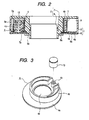
- FIG. 2 is a cross sectional view illustrating the rotating connector
- FIG. 3 is a perspective view illustrating the holder included in the rotating connector
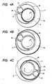
- FIG. 4 is an explanatory view illustrating the operation of the rotating connector.
- the rotating connector relating to the present invention comprises a stator 1; a rotor 2 rotatably coupled to the stator 1; a flat cable 3 electrically connecting the stator 1 and the rotor 2; and a holder 4 rotatably arranged between the stator 1 and the rotor 2.
- the stator 1 is a fid fixed to a steering column, and composed of a resin case 5 and a cover 6 that are made of synthetic resin.
- the case 5 comprises an outer tube 5a and an operculum element 5b protruding outward from the outer surface of the outer tube 5a
- the cover 6 comprises a lower plate 6a and a lower containing element 6b protruding from the outer edge of the lower plate 6a.
- a center hole 6c is formed at the center of the lower plate 6a, and the lower end of the case 5 and the outer edge of the cover 6 are snap-coupled to be a unit, and then the lower opening of the outer tube 5a is closed by the lower plate 6a, and the upper opening of the lower containing element 6b is closed by the operculum element 5b.
- the rotor 2 is a movable element coupled to a handle, and composed of an upper rotor 7 and a lower rotor 8 that are made of synthetic resin.
- the upper rotor 7 comprises an annular upper plate 7a and an inner tube 7b drooped from the center of the upper plate 7a, and an upper containing element 7c is provided on the upper plate 7a.
- the inner tube 7b has an inner diameter that is large enough to be put into a steering shaft, and the lower rotor 8 is incorporated to the inner surface of this inner tube 7b.
- the lower rotor 8 is a cylinder-shaped element having a guard member 8a, and the lower rotor 8 is inserted from the center hole 6c of the cover 6 and snap-coupled to the inner tube 7b, then the rotor 2 is rotatably coupled to the stator 1. And in such a state, the outer tube 5a and the lower plate 6a of the stator 1; and the upper plate 7a and the inner tube 7b of the rotor 2 define a ring-shaped annular space 9 in plan view.
- the flat cable 3 is a belt-shaped transmission line containing a plurality of parallel conductors laminated by a pair of insulation films, and the flat cable 3 is contained in the annular space 9 with itself inverted through a U-shaped inverting section 3a. Both ends of the flat cable 3 are connected with lead blocks 9, 10. One of the lead blocks is fixed in the lower containing element 6b of the cover 6, and this lead block 9 is connected with a lead wire 11 having an external connector 11a at its front end. In addition, the other lead block 10 is fixed in the upper containing element 7c of the upper rotor 7, and connected with a lead wire 12 having an external connector 12a at its front end.
- the holder 4 comprises an annular flat plate 4a loaded on the lower plate 6a of the cover 6; a guiding wall 4b as a guide portion provided on this annular flat plate 4a; and a supporting axis 4c, and these are shaped as one body with synthetic resin.
- the annular flat plate 4a has an outer diameter almost the same as the inner diameter of the outer tube 5a, and has a guide hole 4d formed in its center.
- the guide hole 4d is put into the lower outer circumferential surface of the inner tube 7b, and the holder 4 can slide on the inner tube 7b and rotate in the annular space 9.
- protrusions 4e are formed on the lower face of the annular flat plate 4a to reduce the sliding friction with the lower plate 6a.
- the guiding wall 4b is shaped on the annular flat plate 4a in such a fashion that the guiding wall surrounds almost all the guide hole 4d, and the inner surface of the guiding wall is almost concentric to the guide hole 4d, but the outer circumferential surface is a lot eccentric to the guide hold 4d.
- a part of the guiding wall 4b is notched on the annular flat plate 4a, and a cylinder-shaped supporting axis 4c is provided in the notched portion.
- this supporting axis 4c is rotatably supported a roller 13, and the above-mentioned inverting section 3a of the flat cable 3 is located in the opening 14 formed between the roller 13 and the side face of the guiding wall 4b facing the roller 13 (see FIG. 4). Therefore the distance from the rotating axis of the rotor 2 to the outer wall as an outer portion of the guiding wall 4b becomes the maximum in opposing portions with an opening 14 inserted therebetween, and the minimum in the location that is opposite to the roller 13.
- FIG. 4A illustrates the wound-tight state in which most part of the flat cable 3 is wound on the outer wall of the inner tube 7b. If the rotor 2 is rotated counterclockwise (the direction of arrow A) in this state, the inverting section 3a of the flat cable 3 moves counterclockwise by rotating angle smaller than that of the rotor 2, and the roller 13 and the holder 4 follow the inverting section 3a to move counterclockwise, and, as shown in FIG. 4B, the flat cable 3 is unreeled twice as much as the rotating angle from the inner tube 7b to the inner circumferential surface of the outer tube 5a. If the rotor 2 is further rotated counterclockwise, as shown in FIG.
- the flat cable 3 unreeled to the outer tube 5a is wound on the outer surface of the guiding wall 4b of the holder 4, and, finally, most part of the flat cable is wound on the outer surface of the guiding wall 4b to be in the wound-back state.
- the rotor is rotated clockwise (the direction of arrow B) in the wound-back state shown in FIG. 4C
- the flat cable 3 is unreeled to the inner circumferential surface of the outer tube 5a from the guiding wall 4b, and, if the rotor 2 is further rotated clockwise, as shown in FIG. 4A, most of the flat cable 3 is wound on the outer circumferential surface of the inner tube 7b, the wound-tight state.
- the flat cable 3 is once unreeled to the outer tube 5a located in the outside of the holder 4, but it is wound on the guiding wall 4b of the holder 4 arranged in the annular space in the wound-back state, and the circumference of the outer surface of the guiding wall 4b is much smaller than that of the inner wall of the outer tube 5a, thus the length of the required flat cable 3 can be decreased substantially.
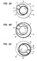
- FIG. 5A illustrates a conventional rotating connector in which the flat cable is wound on the outer tube in the wound-back state
- FIG. 5B illustrates the rotating connector relating to the present embodiment in which the flat cable is wound on the guiding wall of the holder in the wound-back state.
- the inner diameter of the flat cable route (the diameter of the wound-tight state) is r
- the outer diameter of the flat cable route (the diameter of the wound-back state) is R
- the rotatable number of the rotor is N
- the inner diameter r corresponds to the outer diameter of the inner tube of the rotor, and, considering the configuration in which this inner tube is put into the steering shaft, the inner diameter r is same in both rotating connectors illustrated in FIGs. 5A and 5B.
- the outer diameter R corresponds to the inner diameter of the outer tube, however, in the rotating connector in FIG. 5B, the outer diameter R corresponds to the outer diameter of the guiding wall that is smaller than the inner diameter of the outer tube. Therefore it is obvious from the above equation (1) that the outer diameter R of the present embodiment illustrated in FIG. 5B is much smaller than that of the conventional one illustrated in FIG. 5A, the length L of the flat cable 3 can be decreased on condition that the rotatable number N of the rotor 2 is constant.
- the case the guiding wall 4b continuing along the diametric direction is provided on the annular flat plate 4a of the holder 4, however, as shown in FIG. 6, separated guiding walls can be sprinkled along the diametric direction, and the flat cable 3 can be wound in a circular shape on the outer circumferential surface of the guiding wall 4b and the roller 13 even in this case.
- a plotting shape of the outer surface of the guiding wall 4b is not limited to a cylinder, as shown in FIG.
- a non-circular guiding wall is composed of an annular part 4b1 and a regulating part 4b2 and has such a configuration that most inner tube 7b is surrounded by the annular part 4b1, and the regulation part 4b2 protrudes to both sides of the roller 13 from both ends of the annular part 4b1.
- the flat cable 3 is wound on the annular part 4b1 and the regulating part 4b2 of the guiding wall 4b and the roller 13 in an egg-shape.
- the rotating connector using a single piece of flat cable is described.
- the present invention can be applied to the double winding type rotating connector that uses two pieces of flat cables.
- FIG. 8 is a plan view illustrating the holder relating to the second embodiment of the present invention
- FIG. 9 is an explanatory view illustrating the operation of the rotating connector
- FIGs. 10 to 11 are plan views illustrating the modifications of the holder of the present invention.
- the guiding wall 4b of FIG. 8 is provided on the annular flat plate 4a so as to surround most of the guide hole 4d, and its inner surface is a circumferential surface almost concentric to the guide hole 4d, but its outer surface is a circumferential surface eccentric a lot to the guide hole 4d. Between the inner surface and the outer surface of the guiding wall 4b is formed a cavity 4f, which promotes the reduction in the weight of the holder 41.
- concavities and convexities 4g are formed on most of the outer surface of the guiding wall 4b in a fashion that concavities and convexities are alternatively combined along the circumferential direction.
- a part of the guiding wall 4b is notched on the annular flat plate 4a, and in this notched portion is provided a cylinder-shaped supporting axis 4c.
- the roller 13 is rotatably supported by this supporting axis 4c, and the above-mentioned inverting section 3a of the flat cable 3 is located in the opening 14 between the roller 13 and the side face of the guiding wall 4b facing the roller 13 (see FIG. 9). Therefore the distance from the rotating axis of the rotor 2 to the outer surface of the guiding wall 4b becomes the maximum in the vicinity of the opening 14 where the roller is supported, and becomes the minimum in the location that is opposite to the roller 13.
- the flat cable 3 is once unreeled to the outer tube 5a located in the outside of the guiding wall 4b the holder 41, as shown in FIG. 9B, but it is wound on the outer surface of the guiding wall 4b of the holder 4 arranged in the annular space in the wound-back state, and the diameter of the outer surface of the guiding wall 4b is much smaller than that of the inner circumferential surface of the outer tube 5a, thus the length of the required flat cable 3 can be decreased substantially.
- the concavities and convexities reducing the contact area with the flat cable 3 are formed on the outer surface of the guiding wall 4b of the holder 41, thus the flat cable 3 can be unreeled smoothly with no adherence to the outer surface of the guiding wall 4b in the wound-tight operation in which the flat cable 3 is unreeled from the outer surface of the guiding wall 4b, and finally the rotor 2 or the holder 41 can be rotated smoothly.
- the flat cable 3 can be unreeled smoothly from the outer surface of the guiding wall 4b in the wound-tight operation even when a lubricant such as grease etc.
- the concavities and convexities 4g are not formed on the minimum diameter part of the outer surface of the guiding wall 4b, they may be formed along all the outer surface of the guiding wall 4b, and may be formed on the inner surface of the guiding wall 4b in the same pattern.
- the shape of the guiding wall 4b is not limited thereto, what is necessary is the distance from the rotating axis of the rotor 2 to the outer surface of the guiding wall 4b becomes the maximum in the vicinity of the opening 14.
- the guiding wall 4b is composed of the annular part 4b 1 and the regulating part 4b 2 and is non-circularly shaped, as shown in FIGs. 10 to 11, and the flat cable 3 is wound on this guiding wall 4b and the roller 13 in an egg-shape, the weight of the holder 41 can be further reduced.
- the annular part 4b 1 extends in the circumferential direction to surround most of the guide hole 4d, and the regulating part 4b 2 extends outward in the diametric direction from one end of the annular part 4b 1 , and the roller 13 faces the regulating part 4b 2 through the opening 14.
- the shape and the location of the concavities and convexities 4g formed on the guiding wall 4b are not limited thereto, as shown in FIG. 10, the annular part 4b 1 may be shaped like a wave, or, as shown in FIG. 11, a number of cylindrical convexities may be formed on the annular part 4b 1 at regular intervals, or, even though not shown, a number of hemispheric convexities may be sprinkled on the outer surface of the guiding wall 4b, what is necessary is that the concavities and convexities 4g reducing the contact area with the flat cable 3 are formed on the outer surface of the guiding wall 4b.
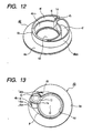
- FIG. 12 is a perspective view illustrating the holder relating to the third embodiment of the present invention.
- the above-mentioned inverting section 3a of the flat cable 3 is located in the opening 14, and the convex wall 4h faces the inner surface of the inverting section 3a, and the concave wall 4i faces the outer surface of the inverting section 3a.
- protrusions are formed on the lower face of the annular flat plate 4a to reduce the sliding friction with the lower plate 6a, and also a cavity 4f is formed between the inner circumferential surface 4b 10 and the outer circumferential surface 4b 20 of the guiding wall 4b to reduce the weight of the holder 42.
- FIG. 13 is a plan view illustrating the holder relating to the fourth embodiment of the present invention.
- the guiding wall 4b of the holder 43 comprises an inner wall 4b 3 as an inner wall portion annularly extending to surround most of the center hole 4d, a concave wall 4i as a coupling wall portion and an opposing wall 4h extending to the outer edge of the annular flat plate 4a from both ends of the inner wall 4b 3 , and a first and second outer walls 4b 4 , 4b 5 as an outer wall portion extending to the inner wall 4b 3 from the outer end of the concave wall 4i and the opposing wall 4i. These are formed continuously in an almost same thickness.
- the concave wall 4i and the opposing wall 4h face to each other through the supporting axis 4c, and the roller 13 is rotatably supported by this supporting axis 4c.
- the above-mentioned intermediate inverting section of the flat cable 3 is located in the opening 14 secured between the roller 13 and the concave wall 4i facing the roller 13, and the flat cable 3 is wound non-circularly on the inner wall 4b 1 and the outer surface of the first and the second outer walls 4b 4 , 4b 5 when it slides to the outer tube 5b from the inner tube 7b through the opening 14.
- the rotating axis of the rotor 2) to the non-circular route P becomes the maximum in the vicinity of the opening 14 where the roller 13 is supported, and becomes smaller along the extending direction of the first and the second outer walls 4b 4 , 4b 5 , and becomes the minimum in the location that is opposite to the roller 13.
- FIG. 14 is a plan view illustrating the holder relating to the fifth embodiment of the present invention
- FIG. 15 is a perspective view illustrating the example of a transformed holder.
- the guide portion 4p of the holder 44 comprises a number of cylindrical guide pins 4m 1 ; and a concave wall 4i and outer wall 4b 4 shaped like a wedge, and the above-mentioned supporting axis 4c and guide pins 4m 1 are provided on the non-circular area S surrounding the guide hole 4d on the annular flat plate 4a at certain intervals.
- the inner edge of the non-circular area S has a circular path S1 concentric to the guide hole 4d, but the outer edge of the non-circular area S has a non-circular path S2 not concentric to the guide hole 4d, shaped like an egg, and most of the guide pins 4m 1 are provided along the circular path S1, and the rest of the guide pins 4m 1 are provided along the non-circular path S2.
- the concave wall 4i extends from the circular path S1 to the outer edge of the annular flat plate 4a, and the outer wall 4b4 extends along the non-circular path S2 from the outer end of the concave wall 4i, and the supporting axis 4c faces the concave wall 4i with a certain distance between them.
- the roller 13 is rotatably supported by this supporting axis 4c, and the above-mentioned inverting section 3a of the flat cable 3 is located in the opening 14 secured between the roller 13 and the concave wall 4i facing the roller 13.
- the flat cable 3 that slides to the outer tube 5a from the inner tube 7b through the opening 14 is wound non-circularly on the outer wall 4b 4 and the guide pins 4m 1 provided along the non-circular path S2. Therefore the distance from the center O of the guide hole 4d (i.e. the rotating axis of the rotor 2) to the non-circular path S2 becomes the maximum in the vicinity of the opening 14 where the roller 13 is supported, and becomes smaller as getting away from the opening 14, and becomes the minimum in the location that is opposite to the roller 13.
- FIG. 15 is a perspective view illustrating the example of a transformed holder 44, and as shown in this figure, this holder 44 has small-diameter rollers 16 rotatably supported by the guide pins 4m 1 as well as the roller 13 rotatably supported by the supporting axis 4c.
- Such a configuration can decrease the friction between the guide pins 4m1 and the flat cable 3, thus the flat cable 3 can be wound tight or back smoothly when the rotor 2 rotates.
- the holder 44 may be formed with lubricative synthetic resin or lubricative materials may be adhered on the outer surface of the guide pins 4m 1 .
- the guide portion 4p composed of a number of cylindrical guide pins 4m1 and the concave wall 4i and the outer wall 4b 4 shaped like a wedge is described, if a plurality of guide pins 4m1 are provided on the location corresponding to the outer wall 4b 4 , the guide portion 4p can be composed of guiding pins 4m1 having an identical shape.
- FIG. 16 is a plan view illustrating the holder of the sixth embodiment of the present invention.
- Hollow tube-shaped walls 4n shown in FIG. 16 are arranged at certain intervals to surround the guide hole 4d of the annular flat plate 4a, and complementary walls 4g are arranged in the circumferential direction between a pair of adjacent hollow tube-shaped walls 4n.
- the center O of this imaginary inner circumferential surface P1 corresponds to the center O of the guide hole 4d (i.e. the center of the inner tube 7b)
- each complementary wall 4q is arranged on the imaginary inner circumferential surface P1.
- the supporting axis 4c is provided in the location that the diameter of the imaginary outer circumferential surface P2 becomes the maximum (the location that the distance to the center O becomes the maximum).
- the roller 13 is rotatably supported by this supporting axis 4c, and the above-mentioned inverting section 3a of the flat cable 3 is located in the opening between the roller 13 and the hollow tube-shaped wall 4n facing the roller 13. Therefore the distance from the rotating axis of the rotor 2 to the imaginary outer circumferential surface P2 joining the outer side of the hollow tube-shaped walls 4n becomes the maximum in the vicinity of the opening 14, and becomes the minimum in the location that is opposite to the roller 13.
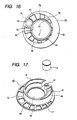
- FIG. 17 is a perspective view illustrating the holder of the seventh embodiment of the present invention
- FIG. 18 is a perspective view illustrating the example of a transformed holder of the present invention.
- both passing holes 17 formed on the annular flat plate 4a and cavities 4f formed in the guiding wall 4b function as a synthetic resin removed part, thus the passing holes 17 and the synthetic resin removed part can reduce the weight of the holder 46.
- penetrating holes 18 functioning as the synthetic resin removed part. These penetrating holes are formed to penetrate the inner surface and the outer surface of the guiding wall 4b, thus part of each penetrating hole 18 is connected with the cavity 45. As above, the cavities 45 and the penetrating holes 18 are formed on the guiding wall 4b as well as the passing hole 17 formed on the annular flat plate 4a, thus these three kinds of synthetic resin removes parts can further reduce the weight of the holder 47.
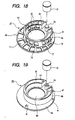
- FIG. 19 is a perspective view illustrating the holder of the eighth embodiment of the present invention
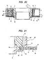
- FIG. 20 is a cross sectional view illustrating the rotating connector comprising the holder of the present invention.
- the holder 48 comprises an annular flat plate 4a loaded on the lower plate 6a of the cover 6; a guiding wall 4b and a supporting axis 4c provided on this annular flat plate 4a, and these members are shaped as one body with a synthetic resin.
- the annular flat plate 4a has an outer diameter almost the same as the inner diameter of the outer tube 5a, and a plurality of resilient tongues 4r as the first resilient urging element are shaped as one body in a cantilevered crossbeam shape on the annular flat plate 4a.
- These resilient tongues 4r are formed along the circumferential direction of the annular flat plate 4a, and at least more than 3 pieces are arranged, for example, at 120-degree intervals, and the front end (free end) extends downward obliquely from the annular flat plate 4a and forms a hemispheric curved face.
- These curved faces of the resilient tongues 4r are in contact with the upper face of the lower plate 6a elastically, and the upper end of the guiding wall 4b is pushed upward to the lower face of the upper plate 7a with the repulsive force (see FIG. 20).
- annular guide hole 4d On the center of the annular flat plate 4a is drilled an annular guide hole 4d, and this guide hole 4d is put into the lower outer circumferential surface of the inner tube 7b, thus the holder 48 slides on the inner tube 7b, and can rotate in the annular space 9.
- the guiding wall 4b of the holder 48 is provided on the annular flat plate 4a to surround most of the guide hole 4d, and the inner surface of the guiding wall 4b is almost concentric to the guide hole 4d, but the outer surface of the guiding wall 4b is a lot eccentric to the guide hole 4d.
- part of the guiding wall 4b is removed on the annular flat plate 4a, and the cylindrical supporting axis 4c is supported by the removed part of the guiding wall 4b.
- the roller 13 is rotatably supported by this supporting axis 4c, and the above-mentioned inverting section 3a of the flat cable 3 is located in the opening 14 between the roller 13 and the side face of the guiding wall 4b facing the roller 13.
- the distance from the rotating axis of the rotor 2 to the outer surface of the guiding wall 4b becomes the maximum in the vicinity of the opening 14 where the roller 13 is supported, and becomes the minimum in the location that is opposite to the roller 13.
- concave cavities 4f are formed between the inner surface and the outer surface of the guiding wall 4b, thus the weigh of the holder 48 can be reduced.
- a plurality of resilient tongues 4r are formed as one body on the annular flat plate 4a of the holder 48, the curved faces in the free ends of the resilient tongues 4r are in contact with the upper face of the lower plate 6a elastically, and the upper end of the guiding wall 4b is pushed upward to the lower face of the upper plate 7a, thus the holder 48 is restrained from moving up and down in the annular space 9 with the resilient urging force of the resilient tongues 4r even when the vibration in the rotating axis direction of the rotor 2 is applied from the external, and, consequently, the collision of the holder 4 with the upper plate 7a or the lower plate 6a can be prevented, and thus the occurrence of noise due to the collision can be decreased (see FIG. 20).
- FIG. 21 is an explanatory view illustrating the engaging part of the rotor and the holder of the ninth embodiment of the present invention
- FIG. 22 is a cross sectional view illustrating the rotating connector comprising the holder of the present invention.
- the rotor 2 is a movable member coupled to a handle, and comprised the upper rotor 7 and the lower rotor 8.
- the upper rotor 7 comprises the annular upper plate 7a and the inner tube 7b drooped from the center of the upper plate 7a, and the upper containing element 7c is provided on the upper face of the upper plate 7a, and the inner tube is a hollow element having the inner diameter large enough to be put into the steering shaft.
- the lower end of the inner tube 7b forms the small-diameter part 7d, and the inner tube 7b and the small-diameter part 7d are connected through the stepped part 7e.
- the outer diameter of the inner tube 7b is set a little larger than that of the center hole 6c of the lower plate 6a, but the outer diameter of the small-diameter part 7d is set a little smaller than that of the center hole 6c.
- the lower rotor 8 is a tube-shaped element having a guarding member 8a, and is inserted through the center hole 6c of the cover 6 to and snap-coupled with the inner surface of the inner tube 7b, thus the rotor 2 is rotatably coupled to the stator 1. And, in such a coupling state, the outer tube 5a and the lower plate 6a of the stator 1 and the inner tube 7b and the upper plate 7a of the rotor 2 define the ring-shaped annular space 9.
- the holder 49 of FIG. 21 comprises the annular flat plate 4a loaded on the lower plate 6a of the cover 6; and the guiding wall 4b and the supporting axis 4c provided on this annular flat plate 4a, and these elements are formed as one body with synthetic resin.
- the annular flat plate 4a has the outer diameter almost the same as the inner diameter of the outer tube 5a, and a plurality of resilient tongues 4r as the second resilient urging element are shaped as one body like a cantilevered crossbeam in this annular flat plate 4a. These elastic tiny pieces 4r are formed along the circumferential direction of the annular flat plate 4a, and at least more than three pieces are formed at regular intervals.
- three resilient tongues ⁇ 4r are formed on the annular flat plate 4a at 120-degree intervals, and the front ends (free end) of the resilient tongues 4r extend downward obliquely from the annular flat plate 4a, and forms a hemispheric curved face.
- the center of the annular flat plate 4a is drilled a circular guide hole 4d, and this guide hole 4d is put into the stepped-part 7e through the small-diameter part 7d of the upper rotor 7, thus the holder 49 can rotate around the inner tube in the annular space 9. In this case, as shown in FIG.
- the annular flat plate 4a and the lower plate 6a are put in between the stepped part 7e of the upper rotor 7 and the guarding part 8a of the lower rotor 8, the resilient tongues 4r of the curved face are in contact with the upper face of the lower plate 6a with the force of P1, thus the repulsive force P2 of P1 exerts upward, and then the circumferential edge of the guide hole 4d is pushed and contacted to the stepped part 7e with the force of P2.
- the small-diameter part 7d connected to the inner tube 7b through the stepped part 7e, and the front ends of the resilient tongues 4r shaped as one body on the annular flat plate 4a of the holder 4 is in contact with the upper face of the lower plate 6a resiliently, thus the circumferential edge of the guide hole 4d put into the small-diameter part 7d is pushed and contacted to the stepped part 7e with the repulsive force from the resilient tongues 4r, thus the holder is restrained from moving up and down in the annular space 9 even when the vibration in the rotating axis direction of the rotor 2 is applied from the external, and the occurrence of noise due to the collision of the holder 4 with the upper plate 7a or the lower plate 6a can be decreased.
- the guiding wall 4b' is formed lower than the guiding wall 4b of FIG. 20, thus, as shown in FIG. 20, even when the resilient tongues 4r are in contact with the upper face of the lower plate 6a resiliently with the force of P1 and the repulsive force P2 of P1 exerts upward, and the circumferential edge of the guide hole 4d is pushed and contacted to the stepped part 7e with the force of P2, the guiding wall 4b' can not reach the lower face of the upper plate 7a.
- FIG. 23 is a cross sectional view illustrating the rotating connector of the tenth embodiment of the present invention.
- first lubricative sheet 19 on the upper face of the lower plate 6a located at the lower opening end of the annular space 9 is adhered a first lubricative sheet 19, and on the lower face of the upper plate 7a located at the upper opening end of the annular space 9 is adhered a second lubricative sheet 20.
- the first and the second lubricative sheets are made of synthetic resin such as polytetrafluoroethylene (PTFE) having an excellent lubricancy, in the case of the present embodiment, these lubricative sheets 19, 20 are directly adhered on the lower plate 6a and the upper plate 7a, but the lubricative sheets may be adhered on the upper plate 6a and the lower plate 7a through sheet-shaped elastic members such as sponges etc.
- PTFE polytetrafluoroethylene
- the protrusions 4e of the holder 50 of FIG. 23 slide on the upper face of the first lubricative sheet 10.
- the first sheet 19 is adhered on the lower plate 6a facing the annular flat plate 4a of the holder 4, thus the holder 4 slides on the first lubricative sheet 19 and rotates in the annular space 9 in the wound-tight or back operation, the discomfort sliding noise from the contact area between the holder 4 and the lower plate 6a can be decreased.
- a plurality of protrusions 4e are formed on the lower face of the annular flat plate 4a, thus the sliding noise between the holder 50 and the first lubricative sheet 19 is decreased substantially, and the holder 4 can rotate smoothly.
- the second lubricative sheet 20 is adhered on the lower face of the upper plate 7a located at the upper opening end of the annular space 9, thus the flat cable 3 is in contact with the second lubricative sheet in the wound-tight or back operation, and the discomfort sliding noise occurred from the contact area between the flat cable 3 and the upper plate 7a can be decreased.
- FIG. 24 is a plan view illustrating the holder of the eleventh embodiment of the present invention.
- each resilient restraining piece 21 extends inward to the annular space 9 and is in contact with the flat cable 3 elastically.
- a supporting element 21a having a hole, thus each resilient restraining piece 21 is supported by the outer tube 5a at 120-degree intervals.
- These resilient restraining pieces 21 curves at a similar rate to the inner surface of the outer tube 5a, and each resilient restraining piece 21 possesses the resilient force that exerts to the outer surface of the guiding wall 4b.
- stator 1 and the rotor 2 including the outer tube 5a or the inner tube 7b are omitted, and the resilient restraining piece 21 are also omitted for the simplification of the figure.
- FIG. 4A illustrates the wound-tight state where most of the flat cable 3 is wound on the outer circumferential surface of the inner tube 7b.
- each resilient restraining piece 21, omitted in the figure is in contact with the outer surface of the guiding wall 4b of the holder 4. If the rotor 2 is rotated counterclockwise (the direction of arrow A) in such a wound-tight state, the inverting section 3a of the flat cable 3 moves counterclockwise by rotating angle smaller than that of the rotor 2, and the roller 13 and the holder 4 follow the inverting section 3a to move counterclockwise, and, as shown in FIG.
- the flat cable 3 is unreeled twice as much as the rotating angle from the inner tube 7b to the inner surface of the outer tube 5a. If the rotor 2 is further rotated counterclockwise, as shown in FIG. 4C, the flat cable 3 unreeled to the outer tube 5a is wound on the outer surface of the guiding wall 4b of the holder 4, and, finally, most part of the flat cable 3 is wound on the outer surface of the guiding wall 4b, the wound-back state.
- each resilient restraining piece 21, omitted in the figure elastically transforms in respond to the change of the flat cable 3 in the diametric direction with the fixed end as a supporting point, for example, in the middle of the wound-back operation shown in FIG.4B, the elastic restraining piece is pushed to the inner surface of the outer tube 5a with the flat cable 3, and in the wound-back state shown in FIG. 4C, it is in contact with the outer surface of the flat cable 3 wound on the guiding wall 4b.
- the rotor is rotated clockwise (the direction of arrow B) in the wound-back state shown in FIG.
- a plurality of resilient restraining pieces extending inward to the annular space 9 are supported by the outer tube 5a of the stator 1, and the flat cable 3 is urged to the outer surface of the guiding wall 4b with the resilient force of the resilient restraining pieces 21, thus the flat cable 3 is restrained from vainly moving in the annular space 9 in the middle of the wound-tight or back operation even when the vibration in the diametric direction of the annular space 9 is applied to the rotating connector from the external.
- three resilient restraining pieces 21 are arranged along the circumferential direction of the outer tube 5a at 120-degree intervals, thus the flat cable 3 can be resiliently urged to the center of the annular space 9 in a balance manner.
- the resilient restraining pieces 21 are formed curved at a similar rate to the inner surface of the outer tube 5a, and the hole of the supporting element 21a formed at one end of these resilient restraining pieces 21 are put into the supporting column formed on the outer tube 5a, and then the resilient restraining pieces 21 are supported by the outer tube 5a in a cantilevered crossbeam shape, thus the resiient restraining pieces 21 can be easily provided on the outer tube 5a.
- the rotating connector using a single piece of flat cable is described, however, it is needless to say that the present invention may be applied to the double winding type rotating connector using two pieces of flat cables.
- FIG. 25 is a cross section view illustrating the rotating connector of the twelfth embodiment of the present invention
- FIG. 26 is a perspective view illustrating the guide portion of the present invention
- FIG. 27 is an explanatory view illustrating the operation of the rotating connector
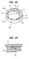
- FIG. 28 is a perspective view illustrating the example of a transformed guide portion of the present invention
- FIG. 29 is an explanatory view of the elastic tiny piece included in the guide portion of the present invention.
- a ring-shaped guide ditch 6d is formed around the center hole 6c of the stator 1.
- the synthetic resin guide portion 50 is C-shaped, and an annular penetrating hole 51a is formed in the center of the guide portion 50.
- This penetrating hole 50a is put into the outer surface of the inner tube 7b, and the guide portion 50 is loaded on the lower plate 6a of the cover 6 and can rotate in the annular space 9.
- An inner surface 4t of the guide portion 50 is concentric to the penetrating hole 50a, but an outer surface 4u of the guide portion 50 is eccentric a lot to the center of the penetrating hole 50a, and the inner surface 4t and the outer surface 4u are connected through the opening 14 in the location that have the maximum eccentric amount.
- the distance from the rotating axis of the rotor 2 to the outer surface 4u of the guide portion 50 becomes the maximum in the vicinity of the opening 14, and the above-mentioned inverting section 3a of the flat cable 3 is located in this opening 14 (see FIG. 27).
- a protrusion 4s is formed at the lower end of the inner surface 4t of the guide portion 50, and is rotatably inserted to the guide ditch 6d formed on the lower plate 6a of the cover 6.
- concave cavities 4v are formed between the inner surface 4t and the outer surface 4u of the guide portion 50, and the weight of the guide portion 50 can be decreased from these cavities 4v.
- stator 1 and the rotor 2 including the outer tube 5a or the inner tube 7b are omitted.
- FIG. 27 illustrates the wound-tight state where most of the flat cable 3 is wound on the outer circumferential surface of the inner tube 7b.
- the flat cable 3 unreeled to the outer tube 5a is wound on the outer surface 4u of the guide portion 50, and, finally, most part of the flat cable is wound on the outer surface 4u of the guide portion 50, the wound-back state.
- the flat cable 3 is unreeled to the inner surface of the outer tube 5a from the outer surface 4u of the guide portion 50, and, if the rotor 2 is further rotated clockwise, as shown in FIG. 27A, most of the flat cable 3 is wound on the outer circumferential surface of the inner tube 7b, the wound-tight state.
- the flat cable 3 is once unreeled to the inner surface of the outer tube 5a located in the outside of the guide portion 50, but it is wound on the outer surface 41 of the guide portion 50 arranged in the annular space 9, and the circumferential length of the outer surface 4u of the guide portion 50 is much smaller than that of the inner surface of the outer tube 5a, thus the length of the required flat cable 3 can be decreased substantially.
- the guide portion 50 is C-shaped, and the outer surface 4u of the guide portion 50 is eccentric to the tube-shaped inner surface 4t, and the protrusion 4s protruded from the lower end of the inner surface 4t of this guide portion 50 is slidably engaged with a ring-shaped guide ditches 6d formed on the lower plate 6a, thus the guide portion 50 can have a smaller diameter to reduce its weight, and can rotate smoothly in the annular space 9.
- the protrusions are formed continuously along the whole lower end of the inner surface 4t of the guide portion 50, however, a plurality of protrusions 4s may be sprinkled intermittently along the lower end of the inner surface 4t.
- FIG. 28 is a perspective view illustrating the example of a transformed guide portion 50.
- a plurality of resilient tongues 4w are formed as one body in a cantilevered crossbeam shape on the upper end of the inner surface 4t of the guide portion 50 as a third resilient urging element.
- At least more than three resilient tongues 4w are formed along the circumferential direction on the inner surface 4t, for example, at 120-degree intervals, and the front end (free end) of the resilient tongue ⁇ 4w protrudes from the upper end of the inner surface 3t and has a hemispheric curved face. As shown in FIG.
- the curved face of resilient tongue 4w is in contact with the lower face of the upper plate 7a of the upper rotor 7 elastically, thus the guide portion 50 is resiliently urged to the upper face of the lower plate a with the repulsive force of the resilient force of the resilient tongue 4w , and the protrusions 4s formed at the lower end of the inner surface 4t of the guide portion 50 are pushed and contacted with the bottom face of the guide ditch 6d.
- the guide portion 50 is restrained from moving up and down in the annular space 9 with the resilient urging force of the resilient tongues 4w even when the vibration in the rotating axis direction of the rotor 2 is applied from the external, and, finally, the collision of the upper end of the guide portion 50 with the lower face of the upper plate 7a can be prevented, and the occurrence of the noise due to the collision can be decreased.
- the rotating connector of the first aspect has the guide portion extending to surround the inner tube with the opening through which the intermediate inverting section of the flat cable is passed as an anchor on the holder that is rotatably arranged in the annular space defined between the inner tube of the rotor and the outer tube of the stator in a fashion that the distance from the rotating axis of the rotor to the outer surface of the guide portion becomes the maximum in the vicinity of the opening, thus the flat cable is wound back on the guide portion with a smaller diameter than that of the outer tube, and thus the length of the required flat cable can be decreased as much.
- the rotating connector of the second aspect has the guiding wall extending to surround the inner tube with the opening through which the intermediate inverting section of the flat cable is passed as an anchor on the holder that is rotatably arranged in the annular space defined between the inner tube of the rotor and the outer tube of the stator in a fashion that the distance from the rotating axis of the rotor to the outer surface of the guiding wall becomes the maximum in the vicinity of the opening, thus the flat cable is wound back on the guiding wall with a smaller diameter than that of the outer tube, and thus the length of the required flat cable can be decreased as much.
- the rotating connector of the third aspect has the guiding wall extending to surround the inner tube with the opening through which the intermediate inverting section of the flat cable is passed as an anchor on the holder that is rotatably arranged in the annular space defined between the inner tube of the rotor and the outer tube of the stator in a fashion that the distance from the rotating axis of the rotor to the outer surface of the guiding wall becomes the maximum in the vicinity of the opening, thus the flat cable is wound back on the guiding wall with a smaller diameter than that of the outer tube, and thus the length of the required flat cable can be decreased as much.
- the convexities and the concavities reducing the contact area with the flat cable are formed on the outer surface of the guiding wall, thus the flat cable can be unreeled smoothly with no adherence to the outer surface of the guiding wall in the wound-tight operation, and the rotor or the holder can rotate smoothly.
- the rotating connector of the fourth aspect has the guiding wall extending to surround the inner tube with the opening through which the intermediate inverting section of the flat cable is passed as an anchor on the holder that is rotatably arranged in the annular space between the inner tube of the rotor and the outer tube of the stator in a fashion that the distance from the rotating axis of the rotor to the outer surface of the guiding wall becomes the maximum in the vicinity of the opening, thus the flat cable is wound back on the guiding wall with a smaller diameter than that of the outer tube, and thus the length of the required flat cable can be shortened substantially as much.
- the concave wall and the convex wall facing to each other are formed as one body in the guiding wall having the inner surface and the eccentric outer surface through the opening, the flat cable can be wound tight or back smoothly by this guiding wall, thus the reduction of the cost can be attained from the simplification of the configuration of the holder.
- the rotating connector of the fifth aspect has the guiding wall extending to surround the inner tube with the opening through which the intermediate inverting section of the flat cable is passed as an anchor on the holder that is rotatably arranged in the annular space between the inner tube of the rotor and the outer tube of the stator in a fashion that the distance from the rotating axis of the rotor to the outer surface of the guiding wall becomes the maximum in the vicinity of the opening, thus the flat cable is wound back on the guiding wall with a smaller diameter than that of the outer tube, and thus the length of the required flat cable can be shortened substantially as much.
- the flat cable is guided by the inner wall portion, the coupling wall portion and the outer wall portion provided on the holder, thus the reduction in the weight and the cost of the holder can be attained, and the holder can be rotated smoothly.
- the rotating connector of the sixth aspect has the guiding wall extending to surround the inner tube with the opening through which the intermediate inverting section of the flat cable is passed as an anchor on the holder that is rotatably arranged in the annular space between the inner tube of the rotor and the outer tube of the stator in a fashion that the distance from the rotating axis of the rotor to the outer surface of the guiding wall becomes the maximum in the vicinity of the opening, thus the flat cable is wound back on the guiding wall with a smaller diameter than that of the outer tube, and thus the length of the required flat cable can be shortened substantially as much.
- the flat cable is guided by a plurality of columns provided in the non-circular area of the holder, thus the reduction in the weight and the cost of the holder can be attained, and the rotor can be rotated smoothly.
- the rotating connector of the seventh aspect has a plurality of hollow tube-shaped walls sprinkled in the circumferential direction to surround the inner tube provided on the synthetic resin holder that is rotatably arranged in the annular space between the inner tube of the rotor and the outer tube of the stator, and an imaginary inner circumferential surface joining the inner side of these hollow tube-shaped walls is set almost concentric to the inner tube, and an imaginary outer circumferential surface joining the outer side of these hollow tube-shaped walls is made eccentric to the center of the inner tube, and the opening through which the intermediate inverting section of the flat cable is passed is provided in the location where the imaginary outer circumferential surface becomes the maximum, thus the flat cable is wound back on the imaginary outer circumferential surface of the hollow tube-shaped walls having smaller diameters than that of the outer tube of the stator, and thus the length of the required flat cable can be decreased substantially.
- each hollow tube-shaped wall guiding the flat cable is shaped a hollow tube-shaped element that contains no synthetic resin in it, thus the reduction in the weight and the
- the rotating connector of the eighth aspect has the annular flat plate having an outer diameter almost the same as the inner diameter of the outer tube on the holder that is rotatably arranged in the annular space between the inner tube of the rotor and the outer tube of the stator, and the guiding wall having the outer surface eccentric to the inner surface extending in a concentric circle shape to the inner tube is provided on this annular flat plate, and the opening through which the intermediate inverting section of the flat cable is passed is provided at the location where the diameter of the guiding wall becomes the maximum, thus the flat cable is wound back on the outer surface of the guiding walls having smaller diameters than that of the outer tube of the stator, and thus the length of the required flat cable can be decreased substantially as much.
- the synthetic resin-removed parts in which synthetic resin is removed are formed on at least one of the annular flat plate of the holder and the guiding wall, thus the reduction in the weight and the cost of the holder can be attained, and the rotor can be rotated smoothly.
- the rotating connector of the ninth aspect defines the annular space between the inner tube and the upper plate of the rotor; and the outer tube and the lower plate of the stator, and has the annular flat plate having the outer diameter almost the same as the inner diameter of the outer tube in the synthetic resin holder that is rotatably arranged in this annular space; a guiding wall having the outer surface eccentric to the inner surface extending in a concentric circle shape to the inner tube on this annular flat plate; and the opening through which the intermediate inverting section of the flat cable is passed provided in the location where the diameter of this guiding wall becomes the maximum, thus the flat cable is wound back on the outer surface of the guiding wall having a smaller diameter than that of the outer tube of the stator, and the length of the required flat cable can be decreased substantially as much.
- the first resilient urging element urging the guiding wall to the upper plate of the rotor is provided on at least one of the lower plate of the stator and the annular flat plate of the holder, thus the holder is restrained from moving up and down in the annular space even when the vibration in the rotating axis direction of the rotor is applied from the external, and thus the noise due to the collision of the holder with the upper plate or the lower plate can be decreased.
- the rotating connector of the tenth aspect defines the annular space between the inner tube and the upper plate of the rotor; and the outer tube and the lower plate of the stator, and has the guiding wall through which the intermediate inverting section of the flat cable is passed provided in the annular flat plate of the holder that is rotatably arranged in this annular space; the inner surface of this guiding wall having the concentric circle shape to the penetrating hole drilled in the center of the annular flat plate; and the guiding wall formed in a fashion that the distance from the rotating axis of the rotor to the outer surface of the guiding wall becomes the maximum in the vicinity of the opening, thus the flat cable is wound back on the outer surface of the guiding wall having a smaller diameter than that of the outer tube, and thus the length of the required flat cable can be decreased substantially as much.
- the small-diameter part coupled through the inner tube and the stepped-part is formed in the rotor, and the penetrating hole of the holder is put into this small-diameter part, and the circumferential edge of the penetrating hole is pushed to the stepped-part by the second resilient urging element, thus the holder is restrained from moving up and down in the annular space even when the vibration in the rotating axis direction of the rotor is applied from the external, and thus the noise due to the collision of the holder with the upper plate or the lower plate can be decreased.
- the rotating connector of the eleventh aspect defines the annular space between the inner tube and the upper plate of the rotor; and the outer tube and the lower plate of the stator, and has the annular flat plate facing the lower plate on the holder that is rotatably arranged in this annular space; the guiding wall having the outer surface eccentric to the inner surface extending in a concentric circle shape to the inner tube on this annular flat plate; and the opening through which the intermediate inverting section of the flat cable is passed provided in the location where the diameter of this guiding wall becomes the maximum, thus the flat cable is wound back on the outer surface of the guiding wall having a smaller diameter than that of the outer tube of the stator, and the length of the required flat cable can be decreased substantially as much.
- the lubricative sheet is adhered on the upper face of the lower plate defining the lower part of the annular space, thus the annular flat plate of the holder slides on the lubricative sheet and rotates in the annular space, and thus the discomfort noise occurred from the contact area between the holder and the lower plate can be decreased.
- the rotating connector of the twelfth aspect defines the annular space between the inner tube of the rotor and the outer tube of the stator, and has the annular flat plate on the holder that is rotatably arranged in this annular space; the guiding wall having the outer surface eccentric to the inner surface extending in a concentric circle shape to the inner tube on this annular flat plate; and the opening through which the intermediate inverting section of the flat cable is passed provided in the location where the diameter of this guiding wall becomes the maximum, thus the flat cable is wound back on the outer surface of the guiding wall having a smaller diameter than that of the outer tube of the stator, and the length of the required flat cable can be decreased substantially as much.
- the resilient restraining elements extending into the annular space are provided in the outer tube, and urge the flat cable to the center of the annular space, thus the vibration of the flat cable in the diametric direction is restrained even when the vibration in the diametric direction of the annular space is applied from the external, and the occurrence of noise can be decreased.
- the annular space is defined between the lower plate and the outer tube of the stator; and the upper plate and the inner tube of the rotor, and the guide portion that is rotatably provided in this annular space is a C-shaped element that has the outer surface eccentric to the inner surface extending in a concentric circle shape to the inner tube, and the opening through which the intermediate inverting section of the flat cable is passed is provided in the location where the diameter of the guide portion becomes the maximum, and also the protrusions protruding from the lower end of the inner surface of the guide portion are slidably engaged with ring-shaped guide ditches formed on the lower plate, thus the flat cable is wound back on the outer surface of the guide portion having a smaller diameter than that of the outer tube of the stator, and the length of the required flat cable can be decreased substantially as much.
- the guide portion is a C-shaped element having the outer wall eccentric to the cylinder-shaped inner wall, and the protrusions protruding from the lower end of this guide portion are slidably engaged with the ring-shaped guide ditches formed on the lower plate of the stator, thus the guide portion can rotate smoothly while the reduction in the weight of the guide portion is sought.
Landscapes
- Engineering & Computer Science (AREA)
- Mechanical Engineering (AREA)
- Electric Cable Arrangement Between Relatively Moving Parts (AREA)
- Steering Controls (AREA)
Applications Claiming Priority (24)
| Application Number | Priority Date | Filing Date | Title |
|---|---|---|---|
| JP2004035157 | 2004-02-12 | ||
| JP2004035157A JP4355229B2 (ja) | 2004-02-12 | 2004-02-12 | 回転コネクタ |
| JP2004120587A JP2005302651A (ja) | 2004-04-15 | 2004-04-15 | 回転コネクタ |
| JP2004120587 | 2004-04-15 | ||
| JP2004140302A JP2005322536A (ja) | 2004-05-10 | 2004-05-10 | 回転コネクタ |
| JP2004140300 | 2004-05-10 | ||
| JP2004140295 | 2004-05-10 | ||
| JP2004140302 | 2004-05-10 | ||
| JP2004140300A JP2005323465A (ja) | 2004-05-10 | 2004-05-10 | 回転コネクタ |
| JP2004140303 | 2004-05-10 | ||
| JP2004140295A JP2005323464A (ja) | 2004-05-10 | 2004-05-10 | 回転コネクタ |
| JP2004140303A JP2005323466A (ja) | 2004-05-10 | 2004-05-10 | 回転コネクタ |
| JP2004181582A JP2006006063A (ja) | 2004-06-18 | 2004-06-18 | 回転コネクタ |
| JP2004181582 | 2004-06-18 | ||
| JP2004188704 | 2004-06-25 | ||
| JP2004188704A JP2006014511A (ja) | 2004-06-25 | 2004-06-25 | 回転コネクタ |
| JP2004188693A JP2006014510A (ja) | 2004-06-25 | 2004-06-25 | 回転コネクタ |
| JP2004188693 | 2004-06-25 | ||
| JP2004194111A JP2006019079A (ja) | 2004-06-30 | 2004-06-30 | 回転コネクタ |
| JP2004194111 | 2004-06-30 | ||
| JP2004201906 | 2004-07-08 | ||
| JP2004201906A JP2006024462A (ja) | 2004-07-08 | 2004-07-08 | 回転コネクタ |
| JP2004214550A JP2006040577A (ja) | 2004-07-22 | 2004-07-22 | 回転コネクタ |
| JP2004214550 | 2004-07-22 |
Publications (1)
| Publication Number | Publication Date |
|---|---|
| EP1564849A1 true EP1564849A1 (de) | 2005-08-17 |
Family
ID=34705484
Family Applications (1)
| Application Number | Title | Priority Date | Filing Date |
|---|---|---|---|
| EP05002908A Withdrawn EP1564849A1 (de) | 2004-02-12 | 2005-02-11 | Drehverbinder |
Country Status (3)
| Country | Link |
|---|---|
| US (1) | US7175453B2 (de) |
| EP (1) | EP1564849A1 (de) |
| KR (1) | KR100732221B1 (de) |
Cited By (3)
| Publication number | Priority date | Publication date | Assignee | Title |
|---|---|---|---|---|
| EP2546937A1 (de) * | 2011-07-12 | 2013-01-16 | Niles Co., Ltd. | Drehverbindervorrichtung |
| EP2571126A4 (de) * | 2010-05-10 | 2013-09-25 | Furukawa Electric Co Ltd | Drehbare konnektorvorrichtung |
| CN113069865A (zh) * | 2021-04-01 | 2021-07-06 | 抚州市鹤达实业有限公司 | 一种变性淀粉生产用空气过滤净化装置 |
Families Citing this family (12)
| Publication number | Priority date | Publication date | Assignee | Title |
|---|---|---|---|---|
| DE502005004145D1 (de) * | 2005-11-25 | 2008-06-26 | Nexans | Vorrichtung zur Signal- bzw. Stromübertragung zwischen Endstellen |
| JP5097364B2 (ja) * | 2006-06-30 | 2012-12-12 | 矢崎総業株式会社 | 舵角センサ組み込み式回転コネクタ装置 |
| US7909361B2 (en) * | 2008-06-10 | 2011-03-22 | GM Global Technology Operations LLC | Vehicular steering wheel and column assembly including torsional damper device |
| JP5123070B2 (ja) * | 2008-06-19 | 2013-01-16 | ナイルス株式会社 | 回転コネクタ装置 |
| CN102110942A (zh) * | 2009-12-25 | 2011-06-29 | 鸿富锦精密工业(深圳)有限公司 | 连接件 |
| EP2542391B1 (de) * | 2010-03-02 | 2014-06-25 | ABB Research Ltd. | System für elektrische verbindung einer gelenkverbindung mit einem roboterwerkzeug und verfahren dafür |
| US20130270399A1 (en) * | 2012-04-13 | 2013-10-17 | Ben Berkowitz | Management of Cables That Traverse Moving Robot Joints |
| JP2014037210A (ja) * | 2012-08-20 | 2014-02-27 | Alps Electric Co Ltd | 回転コネクタ |
| US9579806B2 (en) | 2012-08-23 | 2017-02-28 | Rethink Robotics, Inc. | Robotic power and signal distribution using laminated cable with separator webs |
| KR102160906B1 (ko) * | 2016-03-31 | 2020-09-29 | 후루카와 덴키 고교 가부시키가이샤 | 회전 커넥터 장치 |
| EP3467966B1 (de) * | 2016-05-31 | 2021-08-18 | Alps Alpine Co., Ltd. | Rotationssteckverbinder |
| CN111819739B (zh) * | 2018-03-19 | 2022-06-10 | 古河电气工业株式会社 | 旋转连接器装置以及旋转连接器装置的组装结构 |
Citations (5)
| Publication number | Priority date | Publication date | Assignee | Title |
|---|---|---|---|---|
| DE19534655A1 (de) * | 1995-09-19 | 1997-03-20 | Teves Gmbh Alfred | Transportsystem für einen aufgewickelten elektrischen Leiter mit Wickelsinnumkehrung durch Schleifenbildung |
| FR2753842A1 (fr) * | 1996-09-23 | 1998-03-27 | Magneti Marelli France | Contacteur electrique tournant perfectionne |
| WO2001008272A1 (en) * | 1999-07-26 | 2001-02-01 | Methode Electronics, Inc. | Clockspring having non-compliant and compliant roller members |
| EP1094570A2 (de) * | 1999-10-22 | 2001-04-25 | The Furukawa Electric Co., Ltd. | Drehverbinder |
| JP2002010462A (ja) * | 2000-06-26 | 2002-01-11 | Auto Network Gijutsu Kenkyusho:Kk | 回転接続装置 |
Family Cites Families (10)
| Publication number | Priority date | Publication date | Assignee | Title |
|---|---|---|---|---|
| US4824396A (en) * | 1987-05-27 | 1989-04-25 | Alps Electric Co., Ltd. | Electrical connection apparatus |
| US6012935A (en) * | 1994-07-19 | 2000-01-11 | Methode Electronics, Inc. | Clockspring connector with carrier member |
| JPH08222340A (ja) * | 1994-12-14 | 1996-08-30 | Yazaki Corp | ハンドルとステアリングコラム間の電気的接続装置 |
| JPH09274981A (ja) * | 1995-08-11 | 1997-10-21 | Yazaki Corp | 相対回転部材間継電装置 |
| JPH09148023A (ja) * | 1995-11-21 | 1997-06-06 | Yazaki Corp | 相対回転部材間継電装置 |
| JPH09185982A (ja) * | 1995-12-28 | 1997-07-15 | Nippon Plast Co Ltd | ケーブル用リール装置 |
| JPH11135220A (ja) | 1997-10-28 | 1999-05-21 | Yazaki Corp | クロックスプリング |
| JPH11187553A (ja) * | 1997-12-17 | 1999-07-09 | Harness Syst Tech Res Ltd | 回転接続装置 |
| JP2000048924A (ja) | 1998-07-24 | 2000-02-18 | Furukawa Electric Co Ltd:The | 回転コネクタ |
| JP3627554B2 (ja) * | 1999-01-20 | 2005-03-09 | 松下電器産業株式会社 | 回転コネクタ |
-
2005
- 2005-02-07 KR KR1020050011479A patent/KR100732221B1/ko not_active Expired - Fee Related
- 2005-02-11 EP EP05002908A patent/EP1564849A1/de not_active Withdrawn
- 2005-02-11 US US11/056,778 patent/US7175453B2/en not_active Expired - Fee Related
Patent Citations (5)
| Publication number | Priority date | Publication date | Assignee | Title |
|---|---|---|---|---|
| DE19534655A1 (de) * | 1995-09-19 | 1997-03-20 | Teves Gmbh Alfred | Transportsystem für einen aufgewickelten elektrischen Leiter mit Wickelsinnumkehrung durch Schleifenbildung |
| FR2753842A1 (fr) * | 1996-09-23 | 1998-03-27 | Magneti Marelli France | Contacteur electrique tournant perfectionne |
| WO2001008272A1 (en) * | 1999-07-26 | 2001-02-01 | Methode Electronics, Inc. | Clockspring having non-compliant and compliant roller members |
| EP1094570A2 (de) * | 1999-10-22 | 2001-04-25 | The Furukawa Electric Co., Ltd. | Drehverbinder |
| JP2002010462A (ja) * | 2000-06-26 | 2002-01-11 | Auto Network Gijutsu Kenkyusho:Kk | 回転接続装置 |
Cited By (5)
| Publication number | Priority date | Publication date | Assignee | Title |
|---|---|---|---|---|
| EP2571126A4 (de) * | 2010-05-10 | 2013-09-25 | Furukawa Electric Co Ltd | Drehbare konnektorvorrichtung |
| EP2546937A1 (de) * | 2011-07-12 | 2013-01-16 | Niles Co., Ltd. | Drehverbindervorrichtung |
| US8740626B2 (en) | 2011-07-12 | 2014-06-03 | Valeo Japan Co., Ltd. | Rotational connector device including a spacer disposed in an annular space formed between a rotor and a stator |
| CN113069865A (zh) * | 2021-04-01 | 2021-07-06 | 抚州市鹤达实业有限公司 | 一种变性淀粉生产用空气过滤净化装置 |
| CN113069865B (zh) * | 2021-04-01 | 2022-08-30 | 抚州市鹤达实业有限公司 | 一种变性淀粉生产用空气过滤净化装置 |
Also Published As
| Publication number | Publication date |
|---|---|
| KR100732221B1 (ko) | 2007-06-27 |
| KR20060041857A (ko) | 2006-05-12 |
| US7175453B2 (en) | 2007-02-13 |
| US20050180727A1 (en) | 2005-08-18 |
Similar Documents
| Publication | Publication Date | Title |
|---|---|---|
| EP1564849A1 (de) | Drehverbinder | |
| US8478369B2 (en) | Mobile device | |
| US9115750B2 (en) | Hinge apparatus and computing apparatus having the same | |
| US8808016B2 (en) | Rotatable connector device | |
| US9042089B2 (en) | Computer hinge with hollow and partially annular clutch | |
| EP3807737B1 (de) | Scharnierte vorrichtung | |
| JP4122154B2 (ja) | 非柔軟性ローラ部材と柔軟性ローラ部材とを有するクロックスプリング式コネクタ | |
| JP2011210616A (ja) | 回転コネクタ装置 | |
| JP2011258546A5 (de) | ||
| US8998628B2 (en) | Rotatable connector device | |
| KR20020050749A (ko) | 전자 장치와 이런 전자 장치용 힌지 커넥터 | |
| US7834517B2 (en) | Linear drive ultrasonic motor | |
| KR100568303B1 (ko) | 초소형 안테나 구동장치 | |
| JP2010129285A (ja) | 回転コネクタ装置 | |
| US9022367B2 (en) | Curved spring and slide mechanism | |
| JP2012047336A (ja) | 駆動装置 | |
| JPH1131567A (ja) | 回転コネクタ | |
| EP1936471A1 (de) | Mobile vorrichtung | |
| JP4738193B2 (ja) | 携帯機器のスライド機構及び携帯電話機 | |
| JP2011018618A (ja) | 回転コネクタ | |
| KR102253586B1 (ko) | 스크롤 휠 | |
| JP2005291292A (ja) | トルク伝達機構 | |
| JPH07177642A (ja) | ケーブル用リール装置 | |
| JP2006014510A (ja) | 回転コネクタ | |
| JP2005323465A (ja) | 回転コネクタ |
Legal Events
| Date | Code | Title | Description |
|---|---|---|---|
| PUAI | Public reference made under article 153(3) epc to a published international application that has entered the european phase |
Free format text: ORIGINAL CODE: 0009012 |
|
| AK | Designated contracting states |
Kind code of ref document: A1 Designated state(s): AT BE BG CH CY CZ DE DK EE ES FI FR GB GR HU IE IS IT LI LT LU MC NL PL PT RO SE SI SK TR |
|
| AX | Request for extension of the european patent |
Extension state: AL BA HR LV MK YU |
|
| 17P | Request for examination filed |
Effective date: 20050809 |
|
| AKX | Designation fees paid |
Designated state(s): DE ES FR GB IT |
|
| 17Q | First examination report despatched |
Effective date: 20130712 |
|
| STAA | Information on the status of an ep patent application or granted ep patent |
Free format text: STATUS: THE APPLICATION IS DEEMED TO BE WITHDRAWN |
|
| 18D | Application deemed to be withdrawn |
Effective date: 20131123 |