EP1564859A1 - Boítier à brides pour cloisons creuses - Google Patents
Boítier à brides pour cloisons creuses Download PDFInfo
- Publication number
- EP1564859A1 EP1564859A1 EP04075449A EP04075449A EP1564859A1 EP 1564859 A1 EP1564859 A1 EP 1564859A1 EP 04075449 A EP04075449 A EP 04075449A EP 04075449 A EP04075449 A EP 04075449A EP 1564859 A1 EP1564859 A1 EP 1564859A1
- Authority
- EP
- European Patent Office
- Prior art keywords
- housing
- flange
- flanges
- screw
- shim
- Prior art date
- Legal status (The legal status is an assumption and is not a legal conclusion. Google has not performed a legal analysis and makes no representation as to the accuracy of the status listed.)
- Granted
Links
- 238000000034 method Methods 0.000 claims abstract description 4
- 238000005192 partition Methods 0.000 claims description 73
- 238000003780 insertion Methods 0.000 claims description 11
- 230000037431 insertion Effects 0.000 claims description 11
- 238000005553 drilling Methods 0.000 claims description 4
- 238000012423 maintenance Methods 0.000 claims description 4
- 230000002787 reinforcement Effects 0.000 claims description 3
- 230000000712 assembly Effects 0.000 claims description 2
- 238000000429 assembly Methods 0.000 claims description 2
- 230000004888 barrier function Effects 0.000 abstract 1
- 238000009434 installation Methods 0.000 description 5
- 239000011505 plaster Substances 0.000 description 4
- 241000422252 Cales Species 0.000 description 2
- 238000009413 insulation Methods 0.000 description 2
- 229920000297 Rayon Polymers 0.000 description 1
- 229910000746 Structural steel Inorganic materials 0.000 description 1
- 239000004020 conductor Substances 0.000 description 1
- 230000000994 depressogenic effect Effects 0.000 description 1
- 239000012212 insulator Substances 0.000 description 1
- 238000004519 manufacturing process Methods 0.000 description 1
- 239000002184 metal Substances 0.000 description 1
- 229910052751 metal Inorganic materials 0.000 description 1
- 239000002991 molded plastic Substances 0.000 description 1
- 230000000149 penetrating effect Effects 0.000 description 1
- 238000007747 plating Methods 0.000 description 1
- 239000002964 rayon Substances 0.000 description 1
- 239000002699 waste material Substances 0.000 description 1
- 239000002023 wood Substances 0.000 description 1
Images


Classifications
-
- H—ELECTRICITY
- H02—GENERATION; CONVERSION OR DISTRIBUTION OF ELECTRIC POWER
- H02G—INSTALLATION OF ELECTRIC CABLES OR LINES, OR OF COMBINED OPTICAL AND ELECTRIC CABLES OR LINES
- H02G3/00—Installations of electric cables or lines or protective tubing therefor in or on buildings, equivalent structures or vehicles
- H02G3/02—Details
- H02G3/08—Distribution boxes; Connection or junction boxes
- H02G3/12—Distribution boxes; Connection or junction boxes for flush mounting
- H02G3/123—Distribution boxes; Connection or junction boxes for flush mounting in thin walls
Definitions
- the present invention relates to a flanged housing which is fixed in a hollow partition, in order to embed in this partition an electrical apparatus, such as, for example, a switch or socket.
- Electrical equipment intended to be placed in the housing comprises, in general, a mechanism that fits into the housing, and a facade with an interface, and two oblong holes for the fixing the equipment on the housing.
- the interface consists, for example, in a button in the case where the switchgear is a switch, or two wells in the case where the electrical equipment is a socket.
- the axis of symmetry of each oblong hole of the facade describes an arc of a circle.
- the two oblong holes are, in general, arranged vis-à-vis on the facade of electrical equipment, the axis of this arc being orthogonal to the front of the electrical equipment, so that the axes of the arcs of circle described by the axes of symmetry of the oblong holes are combined along an axis, which will be called principal, and are orthogonal to the facade of electrical equipment.
- At least one end of each oblong hole ends with a circular hole of orthogonal axis to the facade of the apparatus electric.
- the diameter of the orifice is sufficient to allow a head of screw to go through the circular hole.
- the housings include means fastening to the partition, for example flanges, actuated by screws.
- the flanges take support on the back of the hollow partition after the partition has has been drilled to the diameter of the housing with, for example, a hole saw.
- the electrical equipment is fixed on this type of housing to using a first pair of screws, and the flanges of the housing are maneuvered to using a second pair of screws to fix the housing on the partition.
- the flanges are separated from the housing.
- the installer must, when the installation of the housing, actuate the screws of maneuvering the flanges to fix the housing to the bulkhead, then after connecting the electrical equipment to electrical conductors opening inside the housing, fix the apparatus by the screws of this housing.
- the installation of a housing of this type therefore leads at least two maneuvers, which leads to a pose relatively complicated and a waste of time. From an industrial point of view, manufacturers of such cases are forced to develop machines complex to assemble the two pairs of screws and the flanges to the housing, this which causes significant costs passed on the selling price.
- French patent application FR 2 839 818 of the same applicant teaches a flanged case for hollow partitions simpler and faster to pose, allowing a perfect plating of the electrical equipment against the partition.
- the housing comprises two articulated flanges, which can undergo a translational movement and / or rotational movement, each flange being actuated in translation by a screw for fixing the housing in the partition hollow, screwing said screw simultaneously to fix electrical equipment in the housing and pinch the hollow partition between the facade of electrical equipment and flanges.
- the walls of hollow partitions usually have thicknesses of 13 mm, sometimes even 10 mm.
- a plaster wall of the same thickness on the hollow partition which can bring the total thickness of the wall to 26 mm (or 20 mm).
- the housings known in the prior art are easily inserted into a wall of a certain thickness but are not usually not intended to fit very thick walls different.
- the present invention aims to overcome certain disadvantages of the prior art by proposing a flanged housing for hollow partitions which is simple and quick to install and that can adapt to partition walls having very different thicknesses.
- a flanged housing having a portion cylindrical closed by a bottom to fix an electrical equipment in a hollow partition, comprising at least two articulated flanges, each flange being able to undergo a translation movement and / or a rotational movement, and each flange being actuated by a screw to fix the housing in the hollow partition, the flanges and the housing forming a monobloc assembly, characterized in that it also comprises at least two removable shims, each shim being located in the extension of one of the flanges, and in that that the screwing of the screw simultaneously makes it possible to fix the apparatus in the housing and pinch the hollow partition between the facade of electrical equipment and flanges or between the facade of the equipment electrical and each shim sets flange - hold.
- each flange is located in a opening made in the cylindrical part of the housing and delimited by a cut in "U", each flange being connected to the bottom of the housing by a piece arc-shaped which is flexible, allowing rotation of the flange or the entire flange - wedge around the arc-shaped piece to allow inserting the housing into a cylindrical bore of the hollow partition, or to remove the housing from this piercing, the arc-shaped piece being extended by a tongue, at the free end of which is formed a shoulder substantially perpendicular to the tongue.
- each flange comprises at least one ramp formed perpendicularly to the shoulder and the tongue for constitute an angle, the ramp to facilitate the retraction of the flange to allow the insertion of the housing in the drilling of the partition dig.
- a well tapped inside, is formed in the mass of the tongue of each flange, and receives a screw and in this a pair of columns is formed perpendicular to the shoulder of each flange, on the upper surface of the latter, each column of the pair of columns being located on either side of the well to serve as a means guide to each shim.
- each wedge comprises a plate, at a end of which a shoulder is formed substantially perpendicular to said plate, and two grooves, each shim being held in place on the housing, in the extension of a flange, by insertion of the flange columns between the wedge plate and the grooves of the hold, the shoulder of the hold being substantially parallel to the shoulder of the flange, from which it is separated by the height of the plate, and the height of the hold being less than the height of the columns.
- each shim has two reinforcements parallel formed against each plate and each shoulder, and a half-well, of semicircular section, formed in each plate, said half-well welcoming the upper end of the screw screwed into the flange corresponding, and the grooves of the wedge being formed protruding on the outer surface of the half-well, parallel to the axis of the latter.
- the inner radius of the circular section of the half-well is constant and substantially equal to that of the screw in the part of the half-well near the free end of the plate, and constant and substantially equal to that of the head of the screw in the part of the half-well close to the end of the plate integral with the shoulder, the inner radius of the half-well varies continuously between these two parts.
- the flanged housing comprises at least two rounded or flattened W-shaped pieces, the central part of each W-shaped piece rounded or flattened with two bosses for keep a screw snapped into the space available in the part central, each of the bosses being located on either side of the opening of the central portion, and each W-shaped piece rounded or flattened being arranged so as to cooperate with a flange.
- the well of each flange is located in the axis of the central part of the piece in the form of W rounded or flattened associated, and the columns of each flange are located respectively in the axes of the extreme parts of the shaped part W rounded or flattened associated.
- each screw inserted in a means of fixing the electrical equipment, is screwed into the well associated with said screw, and each flange or each flange-shim assembly undergoes a translation movement along the axis of the screw, resulting in the insertion of each pair of columns in the space available in the parts extremes of the rounded or flattened W-shaped part to ensure sandwich the partition between the shoulders of the flanges or wedges and the rear face of the facade of the electrical equipment.
- the means for fixing the apparatus electric comprises at least two oblong holes whose axis of symmetry describes an arc and whose end ends with a portion circular diameter greater than the diameter of the screw head, the spacing of oblong holes being substantially equal to the spacing of the screws.
- the housing has projecting pins on the outer circumference of the housing near its open edge for prevent it from turning relative to the hollow partition and ensure its maintenance pending the installation of the electrical equipment.
- the cylindrical part and / or the bottom of the housing includes one or more releasable lids to allow the connection of electrical equipment to electrical wires in the hollow partition.
- Another object of the invention is to propose a method for removing each shim of the flanged housing according to the invention, before fixing the electrical equipment in a hollow partition using the housing.
- the housing (1) with flanges (4) comprises a cylindrical part (2) closed on one side by a bottom (3), and at least two flanges (4).
- Each flange (4) is located in an opening made in the cylindrical part (2) and delimited by a cutout (9) in the form of U.
- the flanges (4) are substantially located opposite one another. the other.
- Each flange (4) is held in the housing (1) only by a piece of arc shape (44), located between the edge of the flange (4) located near the bottom (3) and the bottom (3), the other three edges of the flange (4) being separated from the rest housing (1) by the cutout (9) U-shaped.
- Each plate (10) rectangular, perpendicular to the bottom (3), are formed on the part inside the cylindrical part (2), each of the plates (10) being and other of the U-shaped cutout (9).
- a rounded W-shaped piece or flattened (6) is formed against each pair of plates (10), between the top of each cutout (9) and the edge (15) of the housing (1).
- Each room W-shaped rounded or flattened (6) is perpendicular to the plates (10) and located on the side of the plates (10) opposite the bottom (3).
- the central part (61) each rounded or flattened W-shaped piece (6) forms a guide in portion of cylinder, open towards the inside of the housing, and delimited by two bosses (610).
- This central part (61), of axis substantially parallel to the axis of symmetry of the housing, allows, due to its shape, to maintain a screw (5) snapped into it.
- the screw (5) can easily be disengaged from the central part (61) thanks to the elasticity of the rounded W-shaped part or flattened (6).
- Each rounded or flattened W-shaped piece (6) is arranged so as to cooperate with a flange (4).
- Each flange (4) comprises, in the extension of the piece arc shape (44), a tongue (42) forming a rectangular, at rest, with the bottom (3) of the housing, an angle of substantially 90 °.
- a shoulder (41) is formed at the free end of each tongue (42), substantially perpendicular to the tongue. When the flange (4) is at rest, this shoulder (42) is then substantially parallel to the bottom (3) of the housing (1) and partly located outside the cylindrical part (2).
- Two ramps (45) parallel are formed against each shoulder (41) and each tongue (42) to form an angle iron, each ramp (45) of the pair of ramps thus formed being located, for example, near each leg of the "U" of the cutout (9).
- a well (7) is dug into the mass of each tongue (42), which accommodates a screw (5) partially screwed into the well (7), ideally before insertion of the housing (1) in the hollow partition (100).
- Each well (7) is threaded by the screw (5) during manufacture of the housing (1).
- the upper part of each screw (5) is then located in the central part (61) of the W-shaped piece rounded or flattened (6), the bosses of each central portion (61) for holding the tongue of each flange (4) substantially parallel to the axis of symmetry of the housing (1).
- a pair of columns (8) is formed on the upper face of each shoulder (41), substantially perpendicular to the shoulder.
- a column (8) of each pair of columns (8) is located on each side of the well (7), such way that each column can penetrate, by translation of the flange (4) along an axis parallel to the axis of the screw (5), in the space available in the end portions (62) of the rounded or flattened W-shaped piece (6) cooperating with the flange (4).
- the presence of the columns (8) thus makes it possible limit the rotational movements of each flange (4) along the axis of the screw (5) during screwing efforts.
- Columns (8) have, for example, a shape rectangular and are for example arranged in the plane of the tongue (42).
- the assembly comprising an arc-shaped piece (44), a tongue (42), a shoulder (41), a pair of ramps (45), a well (7) and a pair of columns (8) forms a flange (4).
- the length of each flange (4) is lower, at rest, at the distance between the bottom (3) of the housing (1) and the rounded or flattened W-shaped piece (6) associated with said flange (4).
- the position of the flanges (4) at rest corresponds to the position of the flanges (4) for which the axis of each well (7) is substantially merged with the axis of the central portion (61) of the rounded or flattened W-shaped piece (6) associated.
- the housing (1) also comprises two shims (12) removable positioning each in the extension of one of the flanges (4), along the screw (5) and columns (8).
- Each shim (12) represented in particular in FIGS. 3a and 3b, consists of a plate (120) at one end of which is formed a shoulder (121) disposed substantially perpendicular to said plate (120) so as to form an element of L-shaped section returned.
- Two reinforcements (122) parallel, for example rectangular, are formed against each plate (120) and each shoulder (121).
- a half-well (123) of semicircular section is formed in each plate (120) and accommodates the upper end of the screw (5) screwed into the corresponding flange (4).
- the inner radius of the section of the half-well (123) is constant and substantially equal to that of the screw (5) in the portion of the half-well (123) near the free end of the plate (120), and constant and substantially equal to that of the head of the screw (5) in the part of the half-well (123) near the end of the plate (120) secured to the shoulder (121). Between these two parts, the inner radius of the half-well (123) varies continuously over a very small portion.
- Each half-well (123) has two grooves (124) projecting from its outer surface, parallel to the axis of the half-well (123).
- grooves (124) allow hold each shim (12) in place on the housing (1), in the extension a flange (4), by inserting the columns (8) of the flange between the plate (120) of the shim (12) and the grooves (124) of the shim (12).
- the shoulder (121) of the shim (12) is substantially parallel to the shoulder (41) of the flange (4), as is visible in particular in Figure 1.
- the height of the wedge (12) is less than the height of the columns (8).
- the housing (1) also comprises at least one detachable lid (11), for example in the form of an ear, on the cylindrical part (2) and / or on the bottom (3) of the housing.
- the detachable covers (11) have a thicker thin than the cylindrical part (2) and the bottom (3) of the housing (1), and are pre-cut, which allows them to be easily detached by a simple finger pressure, exerted while firmly holding the housing.
- the housing (1) comprises a plurality of pins (13) on the periphery outside the cylindrical part (2), close to the open edge (15) of the casing (1), useful when the latter is embedded in a hollow partition (100), both to prevent the casing being pushed too far (1) in the hollow partition (100), and ensure the maintenance of the housing (1) in the hollow partition (100) pending the installation of the apparatus electric.
- a hollow partition (100) consists, in general, of least one wall, for example plaster, arranged parallel to another wall, for example plaster, and supported by a metal frame or in wood, so that a space is between the two walls.
- Another type of hollow partition consists of a wall, for example plaster, comprising an insulator on one of its faces, this wall being glued to a wall on the insulating side. These two types of walls generally have a thickness 13 mm, and more rarely 10 mm. In order to improve the sound insulation, an additional wall can be added against at least one of the walls constituting the hollow partition, the total thickness of this wall thus passing to 26 mm, or more rarely to 23 or 20 mm.
- Housing (1) with flanges (4) for hollow partitions according to the invention allows to adapt to these different wall thicknesses thanks to the wedges (12) removable.
- the distance between the shoulder (41) of each flange (4) and the open edge (15) of the housing (1) is slightly greater than 26 mm and the distance between the shoulder (121) of each shim (12) and the open edge (15) of the housing (1) is slightly greater than 13 mm. So, if the wall of the hollow partition has a thickness 10 or 13 mm, the housing is placed with the wedges, while if the wall of the hollow partition has a thickness of 20, 23 or 26 mm, the shims are removed before the case is installed.
- the shims (12) can easily be inserted on the housing (1) or removed from the latter, as shown in Figures 2a to 2d. when takes place, this step of removing or inserting shims is carried out before insertion of the housing (1) in the hollow partition.
- the flange assembly (4) - shim (12) corresponding is switched to inside the housing by exerting a traction on the screw (5) with the fingers.
- the wedge (12) is then slid towards the edge (15) of the housing (1), along the screw (5), being guided by the columns (8) of the flange (4), until the below the screw head reaches the bottom of the part of the half-well (123) having the widest diameter, as shown in Figure 2b.
- the wall of the hollow partition (100) is pierced by means of a saw bell, which allows to remove a cylindrical piece of the hollow partition (100), over the entire thickness of the wall, the diameter of the cylindrical piece being substantially equal to or slightly greater than the outer diameter of the cylindrical portion (2) of the housing (1).
- the housing (1) with flanges (4) is inserted in place of the cylindrical piece which was removed from the hollow partition (100) using the hole saw, the edge open (15) housing (1) facing the installer.
- the housing (1) is inserted in the hollow partition (100), for example by pulling simultaneously with the fingers each screw (5) partially screwed into the flange (4), to the inside of the housing (1), so that the housing (1) can penetrate into the partition hollow (100).
- Each screw (5) is then disengaged from the central portion (61) of the rounded or flattened W-shaped piece (6) and each flange is subjected to rotation relative to the bottom (3) of the housing (1).
- the flanges (4) can also sink themselves to the inside of the housing (1) without Installer's intervention, by contact with the thickness of the hollow partition (100) on the ramps (45) of the flanges (4).
- the open edge (15) of the housing (1) after insertion of the housing (1) in the partition, is then close to the outer face of the hollow partition (100).
- the distance between the shoulder (41, 121) of each flange (4) or shim (12) and the edge opening (15) of the housing (1) is slightly greater than the thickness of the hollow partition (100) to allow free rotation of each flange (4) or of each flange assembly (4) - wedge (12) behind the thickness of the partition dig.
- each flange (4) or each flange assembly (4) - shim (12) resumes its rest position by rotation towards the outside of the housing (1), either alone or being pushed back by the user who exerts pressure on the screws (5) with the fingers.
- Each screw (5) partially screwed into the well (7) is inserted into the central portion (61) of the W-shaped piece rounded or flattened (6).
- the shoulders (41, 121) of each flange (4) or each shim (12) is then substantially parallel to the inner face of the hollow partition (100) in which the casing (1) has been recessed, and located at proximity of the inner face of this wall, as shown on the figures, respectively, 5a and 5b.
- the well (7) of each flange (4) is located then again substantially in the axis of the central portion (61) of the W-shaped piece rounded or flattened (6) associated.
- At least one detachable seal (11) is detached before insertion of the housing (1) in the hollow partition (100). Just before inserting the housing (1) in the hollow partition, the housing (1) is brought close to the hole left in the partition after removal of the cylindrical piece, so that the sheath containing the ends of the electrical wires present in the partition (100), to which the electrical equipment must be connected, or inserted in the openings left at the location of the detachable parts (11) which have been previously detached.
- the electrical equipment comprises two rigidly fixed parts: the mechanism (not shown) of the electrical equipment and the facade (20). Only the mechanism fits into the housing (1).
- the facade (20 shown in particular in FIG. 4, comprises an interface (50) consisting of example, in two holes if the electrical equipment is a socket, or a button if the switchgear is a switch.
- the facade (20) also comprises two openings (21) arranged opposite each other on the front panel (20), each opening (21) consisting of an oblong hole (215) whose axis of symmetry describes an arc of a circle. At least one end of each opening (21) terminates in a circular orifice (210). The diameter each circular orifice (210) is greater than the diameter of the screw head screws (5) of the housing (1).
- the distance between the screws (5) of the housing (1) is the same as the distance between the two openings (21).
- the surface of the facade (20) of the electrical equipment being larger than the section of the cylindrical part (2) of the housing (1), at least a fraction of the rear face of the facade (20) is located against the outer face of the wall of the partition hollow (100) into which the housing (1) is inserted when the apparatus electrical is inserted into the housing (1).
- each screw (5) of the housing (1) After insertion of the housing (1) in the hollow partition (100), the electrical equipment is brought close to the housing (1) so that the ends of the electrical wires accessible in the housing are connected to the electrical equipment.
- the next step is to insert the mechanism electrical equipment in the housing (1).
- Each screw (5) of the housing (1) partially screwed, then enters a circular hole (210) of the facade (20) of the electrical equipment.
- the electrical equipment is then easily put in place by rotating it around the axis of the housing (1).
- Each screw (5) is then screwed.
- the length of each screw (5) is at least equal to the distance between the edge (15) of the housing (1) and the shoulder (41) of each flange (4), increased by the length of the well (7) associated.
- each screw (5) During the screwing of each screw (5), the pair of columns (8) penetrates the end portions (62) of the rounded W-shaped piece or flattened (6) associated.
- the screwing is stopped when the shoulder (41, 121) of each flange (4) or each shim (12) comes against the inner wall of the hollow partition (100).
- the hollow partition (100), in which is inserted the housing (1), is then sandwiched between the flanges (4) or shims (12) on the one hand, and the rear face of the facade (20) of the electrical equipment on the other hand.
- the electrical equipment is also perfectly plated against the partition.
- the housing (1) can easily be removed from the hollow partition.
- the electrical equipment is first removed from the casing (1) after a partial unscrewing of the screws (5) and a rotation of the facade (20), so as to make each screw (5) of the housing coincide with an orifice circular (210) of the facade (20).
- the ends of the electrical wires are disconnected from the electrical equipment.
- the flanges (4) or the flange (4) - shim (12) assemblies can be returned to the interior of the housing (1), for example by exerting traction on the screws (5) using the fingers.
- the housing (1) is made, for example, molded plastic.
- the housing (1) and the flanges (4) form a unitary assembly.
Landscapes
- Engineering & Computer Science (AREA)
- Architecture (AREA)
- Civil Engineering (AREA)
- Structural Engineering (AREA)
- Casings For Electric Apparatus (AREA)
- Details Of Audible-Bandwidth Transducers (AREA)
- Connection Of Plates (AREA)
- Housings And Mounting Of Transformers (AREA)
Abstract
Description
- rotation de chaque ensemble bride - cale vers l'intérieur du boítier,
- coulissement de chaque cale le long de la vis, guidé par les colonnes de la bride, vers le bord du boítier, jusqu'à ce que le dessous de la tête de vis atteigne le fond de la partie du demi-puits ayant le rayon le plus important,
- basculement de la cale vers l'extérieur du boítier en maintenant la vis inclinée vers l'intérieur du boítier.
- la figure 1 représente une vue en perspective du boítier à brides pour cloisons creuses selon l'invention,
- les figures 2a à 2d représentent les étapes successives de retrait d'une des cales du boítier à brides selon l'invention, vu en coupe,
- les figures 3a et 3b représentent une vue en perspective, respectivement de face et arrière, d'une des cales,
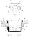
- la figure 4 représente une vue en perspective de la façade de l'appareillage électrique dans un mode de réalisation,
- les figures 5a et 5b représentent une vue en coupe, selon le plan passant par les axes des vis, du boítier à brides selon l'invention, implanté dans une cloison creuse, à paroi respectivement simple ou double.
Claims (14)
- Boítier (1) à brides (4) comportant une partie cylindrique (2) fermée par un fond (3) pour fixer un appareillage électrique dans une cloison creuse (100), comprenant au moins deux brides (4) articulées, chaque bride (4) pouvant subir un mouvement de translation et/ou un mouvement de rotation, et chaque bride (4) étant actionnée par une vis (5) pour fixer le boítier dans la cloison creuse (100), les brides (4) et le boítier formant un ensemble monobloc, caractérisé en ce qu'il comprend également au moins deux cales (12) amovibles, chaque cale (12) étant située dans le prolongement d'une des brides (4), et en ce que le vissage de la vis (5) permet simultanément de fixer l'appareillage électrique dans le boítier (1) et de pincer la cloison creuse (100) entre la façade (20) de l'appareillage électrique et les brides (4) ou entre la façade (20) de l'appareillage électrique et chaque cale (12) des ensembles bride (4) - cale (12).
- Boítier (1) à brides (4) selon la revendication 1, caractérisé en ce que chaque bride (4) est située dans une ouverture pratiquée dans la partie cylindrique (2) du boítier (1) et délimitée par une découpe en "U" (9), chaque bride étant reliée au fond (3) du boítier (1) par une pièce en forme d'arc (44) qui est flexible, permettant la rotation de la bride (4) ou de l'ensemble bride (4) - cale (12) autour de la pièce en forme d'arc (44) pour permettre l'insertion du boítier (1) dans un perçage cylindrique de la cloison creuse, ou pour retirer le boítier (1) de ce perçage, la pièce en forme d'arc (44) étant prolongée par une languette (42), à l'extrémité libre de laquelle est formé un épaulement (41) sensiblement perpendiculaire à la languette (42).
- Boítier (1) à brides (4) selon la revendication 2, caractérisé en ce que chaque bride (4) comprend au moins une rampe (45) formée perpendiculairement à l'épaulement (41) et la languette (42) pour constituer une cornière; la rampe (45) permettant de faciliter l'escamotage de la bride pour permettre l'insertion du boítier (1) dans le perçage de la cloison creuse.
- Boítier (1) à brides (4) selon la revendication 2 ou 3, caractérisé en ce qu'un puits (7), taraudé à l'intérieur, est formé dans la masse de la languette (42) de chaque bride (4), et accueille une vis (5) et en ce qu'une paire de colonnes (8) est formée perpendiculairement à l'épaulement (41) de chaque bride (4), sur la surface supérieure de ce dernier, chaque colonne de la paire de colonnes (8) étant situé de part et d'autre du puits (7) pour servir de moyen de guidage à chaque cale (12).
- Boítier (1) à brides (4) selon la revendication 4, caractérisé en ce que chaque cale (12) comporte une plaque (120), à une extrémité de laquelle un épaulement (121) est formé sensiblement perpendiculairement à ladite plaque (120), et deux rainures (124), chaque cale (12) étant maintenue en place sur le boítier (1), dans le prolongement d'une bride (4), par insertion des colonnes (8) de la bride entre la plaque (120) de la cale (12) et les rainures (124) de la cale (12), l'épaulement (121) de la cale (12) étant sensiblement parallèle à l'épaulement (41) de la bride (4), duquel il est séparé par la hauteur de la plaque (120), et la hauteur de la cale (12) étant inférieure à la hauteur des colonnes (8).
- Boítier (1) à brides (4) selon la revendication 5, caractérisé en ce que chaque cale comporte deux renforts (122) parallèles formés contre chaque plaque (120) et chaque épaulement (121), et un demi-puits (123), de section semi-circulaire, formé dans chaque plaque (120), ledit demi-puits (123) accueillant l'extrémité supérieure de la vis (5) vissée dans la bride (4) correspondante, et les rainures (124) de la cale étant formées en saillie sur la surface extérieure du demi-puits (123), parallèlement à l'axe de ce dernier.
- Boítier (1) à brides (4) selon la revendication 6, caractérisé en ce que le rayon interne de la section circulaire du demi-puits (123) est constant et sensiblement égal à celui de la vis (5) dans la partie du demi-puits (123) proche de l'extrémité libre de la plaque (120), et constant et sensiblement égal à celui de la tête de la vis (5) dans la partie du demi-puits (123) proche de l'extrémité de la plaque (120) solidaire de l'épaulement (121), le rayon interne du demi-puits (123) varie de façon continue entre ces deux parties.
- Boítier (1) à brides (4) selon une des revendications 4 à 7, caractérisé en ce qu'il comprend au moins deux pièces en forme de W arrondi ou aplati (6), la partie centrale (61) de chaque pièce en forme de W arrondi ou aplati (6) comportant deux bossages (610) pour maintenir une vis (5) encliquetée dans l'espace disponible dans la partie centrale (61), chacun des bossages (610) étant situé de part et d'autre de l'ouverture de la partie centrale (61), et chaque pièce en forme de W arrondi ou aplati étant disposée de façon à pouvoir coopérer avec une bride (4).
- Boítier (1) à brides (4) selon la revendication 8, caractérisé en ce que, le boítier étant au repos, le puits (7) de chaque bride (4) se situe dans l'axe de la partie centrale (61) de la pièce en forme de W arrondi ou aplati (6) associée, et les colonnes (8) de chaque bride (4) se situent respectivement dans les axes des parties extrêmes (62) de la pièce en forme de W arrondi ou aplati (6) associée.
- Boítier (1) à brides (4) selon la revendication 9, caractérisé en ce que, l'arrière de l'appareillage électrique étant inséré dans le boítier encastré dans la cloison creuse, chaque vis (5), insérée dans un moyen de fixation (21) de l'appareillage électrique, est vissée dans le puits (7) associé à ladite vis (5), et chaque bride (4) ou chaque ensemble bride (4) - cale (12) subit un mouvement de translation selon l'axe de la vis (5), entraínant l'insertion de chaque paire de colonnes (8) dans l'espace disponible dans les parties extrêmes (62) de la pièce en forme de W arrondi ou aplati, pour assurer la prise en sandwich de la cloison (100) entre les épaulements (41, 121) des brides (4) ou des cales (12) et la face arrière de la façade (20) de l'appareillage électrique.
- Boítier à brides (4) selon la revendication 10, caractérisé en ce que le moyen de fixation (21) de l'appareillage électrique comprend au moins deux trous oblongs (215) dont l'axe de symétrie décrit un arc de cercle et dont une extrémité se termine par une portion circulaire (210) de diamètre supérieur au diamètre de la tête de vis (5), l'entraxe des trous oblongs (215) étant sensiblement égale à l'entraxe des vis (5).
- Boítier (1) à brides (4) selon une des revendications 1 à 11, caractérisé en ce que le boítier (1) comporte des picots (13) en saillie sur le pourtour extérieur du boítier (1) à proximité de son bord ouvert (15) pour l'empêcher de tourner par rapport à la cloison creuse (100) et assurer son maintien en attendant la mise en place de l'appareillage électrique.
- Boítier (1) à brides (4) selon une des revendications 1 à 12, caractérisé en ce que la partie cylindrique (2) et/ou le fond (3) du boítier (1) comprend un ou plusieurs opercules détachables (11) pour permettre la connexion de l'appareillage électrique à des fils électriques situés dans la cloison creuse (100).
- Procédé pour retirer chaque cale (12) du boítier (1) à brides (4) selon une des revendications 1 à 13, avant fixation de l'appareillage électrique dans une cloison creuse (100) à l'aide du boítier, caractérisé en ce qu'il comprend les étapes suivantes :rotation de chaque ensemble bride (4) - cale (12) vers l'intérieur du boítier (1),coulissement de chaque cale (12) le long de la vis (5), guidé par les colonnes (8) de la bride (4), vers le bord (15) du boítier, jusqu'à ce que le dessous de la tête de vis (5) atteigne le fond de la partie du demi-puits (123) ayant le rayon le plus important,basculement de la cale (12) vers l'extérieur du boítier (1) en maintenant la vis (5) inclinée vers l'intérieur du boítier (1).
Priority Applications (3)
| Application Number | Priority Date | Filing Date | Title |
|---|---|---|---|
| DE602004024281T DE602004024281D1 (de) | 2004-02-13 | 2004-02-13 | Flanschgehäuse für eine dünne Wand |
| EP04075449A EP1564859B1 (fr) | 2004-02-13 | 2004-02-13 | Boîtier à brides pour cloisons creuses |
| AT04075449T ATE450071T1 (de) | 2004-02-13 | 2004-02-13 | Flanschgehäuse für eine dünne wand |
Applications Claiming Priority (1)
| Application Number | Priority Date | Filing Date | Title |
|---|---|---|---|
| EP04075449A EP1564859B1 (fr) | 2004-02-13 | 2004-02-13 | Boîtier à brides pour cloisons creuses |
Publications (2)
| Publication Number | Publication Date |
|---|---|
| EP1564859A1 true EP1564859A1 (fr) | 2005-08-17 |
| EP1564859B1 EP1564859B1 (fr) | 2009-11-25 |
Family
ID=34684719
Family Applications (1)
| Application Number | Title | Priority Date | Filing Date |
|---|---|---|---|
| EP04075449A Expired - Lifetime EP1564859B1 (fr) | 2004-02-13 | 2004-02-13 | Boîtier à brides pour cloisons creuses |
Country Status (3)
| Country | Link |
|---|---|
| EP (1) | EP1564859B1 (fr) |
| AT (1) | ATE450071T1 (fr) |
| DE (1) | DE602004024281D1 (fr) |
Cited By (12)
| Publication number | Priority date | Publication date | Assignee | Title |
|---|---|---|---|---|
| GB2469515A (en) * | 2009-04-17 | 2010-10-20 | Demetri Kiloni | Electrical back box with flange |
| EP2328238A1 (fr) * | 2009-11-23 | 2011-06-01 | A. & H. Meyer GmbH Leuchten und Büroelektrik | Dispositif de prise pour meuble |
| WO2011082228A1 (fr) * | 2009-12-30 | 2011-07-07 | Robert Bosch Gmbh | Dispositif de montage encastré à colliers rentrés |
| EP3059823A1 (fr) * | 2015-02-20 | 2016-08-24 | ABB Oy | Boîtier de montage |
| EP3159989A1 (fr) | 2015-10-21 | 2017-04-26 | Legrand France | Boîte électrique à encastrer dans une paroi |
| EP3159988A1 (fr) * | 2015-10-21 | 2017-04-26 | Legrand France | Boîte électrique encastrable dans des cloisons d'épaisseurs différentes |
| CN111049081A (zh) * | 2020-01-09 | 2020-04-21 | 扬州朗日新能源科技有限公司 | 一种套接式接线盒 |
| CN111130036A (zh) * | 2020-01-09 | 2020-05-08 | 扬州朗日新能源科技有限公司 | 一种卡接式接线盒 |
| CN111181103A (zh) * | 2020-01-03 | 2020-05-19 | 扬州朗日新能源科技有限公司 | 一种插接式接线盒 |
| RU2766941C1 (ru) * | 2021-04-16 | 2022-03-16 | Михаил Иванович Решетников | "Установочная коробка" |
| RU229801U1 (ru) * | 2023-12-11 | 2024-10-30 | Константин Борисович Власов | Электромонтажная установочная коробка для сплошных стен |
| WO2025107339A1 (fr) * | 2023-11-22 | 2025-05-30 | 宁波金氏实业有限公司 | Boîtier discret étanche à l'air |
Families Citing this family (1)
| Publication number | Priority date | Publication date | Assignee | Title |
|---|---|---|---|---|
| EP4369541A1 (fr) * | 2022-11-11 | 2024-05-15 | Schneider Electric Industries Sas | Ensemble d'installation de caisson de plafond |
Citations (2)
| Publication number | Priority date | Publication date | Assignee | Title |
|---|---|---|---|---|
| DE2355826A1 (de) * | 1973-11-08 | 1975-05-22 | Spelsberg Guenther Kg | Wanddose fuer elektroinstallationszwecke |
| FR2839818A1 (fr) * | 2002-05-17 | 2003-11-21 | Alombard Sa | Boitier a brides pour cloisons creuses |
-
2004
- 2004-02-13 DE DE602004024281T patent/DE602004024281D1/de not_active Expired - Fee Related
- 2004-02-13 EP EP04075449A patent/EP1564859B1/fr not_active Expired - Lifetime
- 2004-02-13 AT AT04075449T patent/ATE450071T1/de not_active IP Right Cessation
Patent Citations (2)
| Publication number | Priority date | Publication date | Assignee | Title |
|---|---|---|---|---|
| DE2355826A1 (de) * | 1973-11-08 | 1975-05-22 | Spelsberg Guenther Kg | Wanddose fuer elektroinstallationszwecke |
| FR2839818A1 (fr) * | 2002-05-17 | 2003-11-21 | Alombard Sa | Boitier a brides pour cloisons creuses |
Cited By (16)
| Publication number | Priority date | Publication date | Assignee | Title |
|---|---|---|---|---|
| GB2469515A (en) * | 2009-04-17 | 2010-10-20 | Demetri Kiloni | Electrical back box with flange |
| EP2328238A1 (fr) * | 2009-11-23 | 2011-06-01 | A. & H. Meyer GmbH Leuchten und Büroelektrik | Dispositif de prise pour meuble |
| EP2328238B1 (fr) | 2009-11-23 | 2015-11-11 | A. & H. Meyer GmbH Leuchten und Büroelektrik | Dispositif de prise pour meuble |
| WO2011082228A1 (fr) * | 2009-12-30 | 2011-07-07 | Robert Bosch Gmbh | Dispositif de montage encastré à colliers rentrés |
| US8245993B2 (en) | 2009-12-30 | 2012-08-21 | Bosch Security Systems | Recessed mount with stowed clamps |
| EP3059823A1 (fr) * | 2015-02-20 | 2016-08-24 | ABB Oy | Boîtier de montage |
| FR3042918A1 (fr) * | 2015-10-21 | 2017-04-28 | Legrand France | Boite electrique encastrable dans des cloisons d'epaisseurs differentes |
| EP3159988A1 (fr) * | 2015-10-21 | 2017-04-26 | Legrand France | Boîte électrique encastrable dans des cloisons d'épaisseurs différentes |
| EP3159989A1 (fr) | 2015-10-21 | 2017-04-26 | Legrand France | Boîte électrique à encastrer dans une paroi |
| RU2717572C2 (ru) * | 2015-10-21 | 2020-03-24 | Легран Франс | Электрическая коробка, заделываемая в перегородки разной толщины |
| CN111181103A (zh) * | 2020-01-03 | 2020-05-19 | 扬州朗日新能源科技有限公司 | 一种插接式接线盒 |
| CN111049081A (zh) * | 2020-01-09 | 2020-04-21 | 扬州朗日新能源科技有限公司 | 一种套接式接线盒 |
| CN111130036A (zh) * | 2020-01-09 | 2020-05-08 | 扬州朗日新能源科技有限公司 | 一种卡接式接线盒 |
| RU2766941C1 (ru) * | 2021-04-16 | 2022-03-16 | Михаил Иванович Решетников | "Установочная коробка" |
| WO2025107339A1 (fr) * | 2023-11-22 | 2025-05-30 | 宁波金氏实业有限公司 | Boîtier discret étanche à l'air |
| RU229801U1 (ru) * | 2023-12-11 | 2024-10-30 | Константин Борисович Власов | Электромонтажная установочная коробка для сплошных стен |
Also Published As
| Publication number | Publication date |
|---|---|
| EP1564859B1 (fr) | 2009-11-25 |
| DE602004024281D1 (de) | 2010-01-07 |
| ATE450071T1 (de) | 2009-12-15 |
Similar Documents
| Publication | Publication Date | Title |
|---|---|---|
| EP1564859B1 (fr) | Boîtier à brides pour cloisons creuses | |
| FR2754640A1 (fr) | Borne de connexion automatique, et appareil electrique equipe d'une telle borne de connexion | |
| EP1189323B1 (fr) | Dispositif pour l'implantation encastrée d'au moins un appareillage électrique dans un conduit de câblage de profondeur inférieure à celle de l'appareillage. | |
| EP2966741B1 (fr) | Support d'appareillage à monter dans une boîte d'encastrement et mécanisme d'appareillage électrique équipé d'un tel support d'appareillage | |
| EP0452462B1 (fr) | Appareil electrique de commande et/ou de signalisation destine a etre fixe dans une ouverture d'une paroi | |
| EP2112734B1 (fr) | Appareillage électrique à rapporter sur une boite d'encastrement | |
| EP1744427B1 (fr) | Coffret pour appareillages électriques à profondeur variable | |
| FR2842655A1 (fr) | Connecteur de derivation isole destine a etre pose a distance sur une ligne de distribution d'energie electrique aerienne | |
| EP1564860B1 (fr) | Boîtier pour cloisons creuses pourvu de brides d'adaptation à l'épaisseur de cloison | |
| FR2839819A1 (fr) | Boitier a brides pour cloisons creuses | |
| FR2839818A1 (fr) | Boitier a brides pour cloisons creuses | |
| EP1744426B1 (fr) | Coffret électrique comprenant deux éléments fixés l'un à l'autre au moyen d'un système à crémaillère | |
| EP0923176B1 (fr) | Accessoire de fixation à griffe, notamment pour boíte d'encastrement et boíte d'encastrement correspondante | |
| FR2956257A1 (fr) | Organe de pre-assemblage d'un chassis d'appareil electrique sur une goulotte electrique, appareil electrique comportant un tel organe de pre -assemblage, et procede de fixation d'un tel organe de pre-assemblage sur le chassis d'un tel appareil electrique | |
| EP1164676A1 (fr) | Dispositif de montage d'un appareil électrique sur un conduit de câblage | |
| EP2320532B1 (fr) | Dispositif de montage d'un montant de châssis sur le fond d'un coffret électrique et coffret électrique comprenant un tel dispositif | |
| EP2500981A1 (fr) | Dispositif de connexion électrique pour mise à la terre de structures métalliques | |
| EP1458074A1 (fr) | Boíte d'encastrement en deux parties pour appareillage électrique | |
| FR3087214A1 (fr) | Boîtier de banche pour la pose de raccord de plomberie | |
| FR2681402A1 (fr) | Profiles d'ossature, notamment pour armoire pour appareillages electriques, et accessoires susceptibles d'etre associes a un tel profile d'ossature. | |
| FR2486173A1 (fr) | Dispositif de fixation pour appareils a encastrer | |
| FR2764361A1 (fr) | Double bride pour canalisations de surface | |
| FR2843496A1 (fr) | Bloc de jonction electrique a fenetre autobloquante | |
| FR3141633A1 (fr) | Ensemble cadre de maintien de douilles | |
| EP3163698B1 (fr) | Support d'appareillage électrique |
Legal Events
| Date | Code | Title | Description |
|---|---|---|---|
| PUAI | Public reference made under article 153(3) epc to a published international application that has entered the european phase |
Free format text: ORIGINAL CODE: 0009012 |
|
| AK | Designated contracting states |
Kind code of ref document: A1 Designated state(s): AT BE BG CH CY CZ DE DK EE ES FI FR GB GR HU IE IT LI LU MC NL PT RO SE SI SK TR |
|
| AX | Request for extension of the european patent |
Extension state: AL LT LV MK |
|
| 17P | Request for examination filed |
Effective date: 20050922 |
|
| AKX | Designation fees paid |
Designated state(s): AT BE BG CH CY CZ DE DK EE ES FI FR GB GR HU IE IT LI LU MC NL PT RO SE SI SK TR |
|
| 17Q | First examination report despatched |
Effective date: 20081107 |
|
| RAP1 | Party data changed (applicant data changed or rights of an application transferred) |
Owner name: ALOMBARD |
|
| GRAP | Despatch of communication of intention to grant a patent |
Free format text: ORIGINAL CODE: EPIDOSNIGR1 |
|
| GRAS | Grant fee paid |
Free format text: ORIGINAL CODE: EPIDOSNIGR3 |
|
| GRAA | (expected) grant |
Free format text: ORIGINAL CODE: 0009210 |
|
| AK | Designated contracting states |
Kind code of ref document: B1 Designated state(s): AT BE BG CH CY CZ DE DK EE ES FI FR GB GR HU IE IT LI LU MC NL PT RO SE SI SK TR |
|
| REG | Reference to a national code |
Ref country code: GB Ref legal event code: FG4D Free format text: NOT ENGLISH |
|
| REG | Reference to a national code |
Ref country code: CH Ref legal event code: EP |
|
| REG | Reference to a national code |
Ref country code: IE Ref legal event code: FG4D |
|
| REF | Corresponds to: |
Ref document number: 602004024281 Country of ref document: DE Date of ref document: 20100107 Kind code of ref document: P |
|
| REG | Reference to a national code |
Ref country code: NL Ref legal event code: VDEP Effective date: 20091125 |
|
| PG25 | Lapsed in a contracting state [announced via postgrant information from national office to epo] |
Ref country code: PT Free format text: LAPSE BECAUSE OF FAILURE TO SUBMIT A TRANSLATION OF THE DESCRIPTION OR TO PAY THE FEE WITHIN THE PRESCRIBED TIME-LIMIT Effective date: 20100325 Ref country code: FI Free format text: LAPSE BECAUSE OF FAILURE TO SUBMIT A TRANSLATION OF THE DESCRIPTION OR TO PAY THE FEE WITHIN THE PRESCRIBED TIME-LIMIT Effective date: 20091125 Ref country code: SE Free format text: LAPSE BECAUSE OF FAILURE TO SUBMIT A TRANSLATION OF THE DESCRIPTION OR TO PAY THE FEE WITHIN THE PRESCRIBED TIME-LIMIT Effective date: 20091125 |
|
| PG25 | Lapsed in a contracting state [announced via postgrant information from national office to epo] |
Ref country code: SI Free format text: LAPSE BECAUSE OF FAILURE TO SUBMIT A TRANSLATION OF THE DESCRIPTION OR TO PAY THE FEE WITHIN THE PRESCRIBED TIME-LIMIT Effective date: 20091125 Ref country code: CY Free format text: LAPSE BECAUSE OF FAILURE TO SUBMIT A TRANSLATION OF THE DESCRIPTION OR TO PAY THE FEE WITHIN THE PRESCRIBED TIME-LIMIT Effective date: 20091125 |
|
| REG | Reference to a national code |
Ref country code: IE Ref legal event code: FD4D |
|
| PG25 | Lapsed in a contracting state [announced via postgrant information from national office to epo] |
Ref country code: AT Free format text: LAPSE BECAUSE OF FAILURE TO SUBMIT A TRANSLATION OF THE DESCRIPTION OR TO PAY THE FEE WITHIN THE PRESCRIBED TIME-LIMIT Effective date: 20091125 |
|
| PG25 | Lapsed in a contracting state [announced via postgrant information from national office to epo] |
Ref country code: RO Free format text: LAPSE BECAUSE OF FAILURE TO SUBMIT A TRANSLATION OF THE DESCRIPTION OR TO PAY THE FEE WITHIN THE PRESCRIBED TIME-LIMIT Effective date: 20091125 Ref country code: NL Free format text: LAPSE BECAUSE OF FAILURE TO SUBMIT A TRANSLATION OF THE DESCRIPTION OR TO PAY THE FEE WITHIN THE PRESCRIBED TIME-LIMIT Effective date: 20091125 Ref country code: EE Free format text: LAPSE BECAUSE OF FAILURE TO SUBMIT A TRANSLATION OF THE DESCRIPTION OR TO PAY THE FEE WITHIN THE PRESCRIBED TIME-LIMIT Effective date: 20091125 Ref country code: DK Free format text: LAPSE BECAUSE OF FAILURE TO SUBMIT A TRANSLATION OF THE DESCRIPTION OR TO PAY THE FEE WITHIN THE PRESCRIBED TIME-LIMIT Effective date: 20091125 Ref country code: BG Free format text: LAPSE BECAUSE OF FAILURE TO SUBMIT A TRANSLATION OF THE DESCRIPTION OR TO PAY THE FEE WITHIN THE PRESCRIBED TIME-LIMIT Effective date: 20100225 Ref country code: IE Free format text: LAPSE BECAUSE OF FAILURE TO SUBMIT A TRANSLATION OF THE DESCRIPTION OR TO PAY THE FEE WITHIN THE PRESCRIBED TIME-LIMIT Effective date: 20091125 Ref country code: ES Free format text: LAPSE BECAUSE OF FAILURE TO SUBMIT A TRANSLATION OF THE DESCRIPTION OR TO PAY THE FEE WITHIN THE PRESCRIBED TIME-LIMIT Effective date: 20100308 |
|
| BERE | Be: lapsed |
Owner name: ALOMBARD Effective date: 20100228 |
|
| PG25 | Lapsed in a contracting state [announced via postgrant information from national office to epo] |
Ref country code: SK Free format text: LAPSE BECAUSE OF FAILURE TO SUBMIT A TRANSLATION OF THE DESCRIPTION OR TO PAY THE FEE WITHIN THE PRESCRIBED TIME-LIMIT Effective date: 20091125 Ref country code: CZ Free format text: LAPSE BECAUSE OF FAILURE TO SUBMIT A TRANSLATION OF THE DESCRIPTION OR TO PAY THE FEE WITHIN THE PRESCRIBED TIME-LIMIT Effective date: 20091125 |
|
| REG | Reference to a national code |
Ref country code: CH Ref legal event code: PL |
|
| PLBE | No opposition filed within time limit |
Free format text: ORIGINAL CODE: 0009261 |
|
| STAA | Information on the status of an ep patent application or granted ep patent |
Free format text: STATUS: NO OPPOSITION FILED WITHIN TIME LIMIT |
|
| GBPC | Gb: european patent ceased through non-payment of renewal fee |
Effective date: 20100225 |
|
| PG25 | Lapsed in a contracting state [announced via postgrant information from national office to epo] |
Ref country code: LI Free format text: LAPSE BECAUSE OF NON-PAYMENT OF DUE FEES Effective date: 20100228 Ref country code: GR Free format text: LAPSE BECAUSE OF FAILURE TO SUBMIT A TRANSLATION OF THE DESCRIPTION OR TO PAY THE FEE WITHIN THE PRESCRIBED TIME-LIMIT Effective date: 20100226 Ref country code: MC Free format text: LAPSE BECAUSE OF NON-PAYMENT OF DUE FEES Effective date: 20100301 Ref country code: CH Free format text: LAPSE BECAUSE OF NON-PAYMENT OF DUE FEES Effective date: 20100228 |
|
| 26N | No opposition filed |
Effective date: 20100826 |
|
| PG25 | Lapsed in a contracting state [announced via postgrant information from national office to epo] |
Ref country code: DE Free format text: LAPSE BECAUSE OF NON-PAYMENT OF DUE FEES Effective date: 20100901 Ref country code: BE Free format text: LAPSE BECAUSE OF NON-PAYMENT OF DUE FEES Effective date: 20100228 |
|
| PG25 | Lapsed in a contracting state [announced via postgrant information from national office to epo] |
Ref country code: GB Free format text: LAPSE BECAUSE OF NON-PAYMENT OF DUE FEES Effective date: 20100225 Ref country code: IT Free format text: LAPSE BECAUSE OF FAILURE TO SUBMIT A TRANSLATION OF THE DESCRIPTION OR TO PAY THE FEE WITHIN THE PRESCRIBED TIME-LIMIT Effective date: 20091125 |
|
| PG25 | Lapsed in a contracting state [announced via postgrant information from national office to epo] |
Ref country code: LU Free format text: LAPSE BECAUSE OF NON-PAYMENT OF DUE FEES Effective date: 20100213 Ref country code: HU Free format text: LAPSE BECAUSE OF FAILURE TO SUBMIT A TRANSLATION OF THE DESCRIPTION OR TO PAY THE FEE WITHIN THE PRESCRIBED TIME-LIMIT Effective date: 20100526 |
|
| PG25 | Lapsed in a contracting state [announced via postgrant information from national office to epo] |
Ref country code: TR Free format text: LAPSE BECAUSE OF FAILURE TO SUBMIT A TRANSLATION OF THE DESCRIPTION OR TO PAY THE FEE WITHIN THE PRESCRIBED TIME-LIMIT Effective date: 20091125 |
|
| REG | Reference to a national code |
Ref country code: FR Ref legal event code: PLFP Year of fee payment: 13 |
|
| REG | Reference to a national code |
Ref country code: FR Ref legal event code: PLFP Year of fee payment: 14 |
|
| REG | Reference to a national code |
Ref country code: FR Ref legal event code: PLFP Year of fee payment: 15 |
|
| PGFP | Annual fee paid to national office [announced via postgrant information from national office to epo] |
Ref country code: FR Payment date: 20200113 Year of fee payment: 17 |
|
| PG25 | Lapsed in a contracting state [announced via postgrant information from national office to epo] |
Ref country code: FR Free format text: LAPSE BECAUSE OF NON-PAYMENT OF DUE FEES Effective date: 20210228 |