EP1564863A1 - Réseau de bord d'un véhicule avec accumulation du courant de générateur indépendant de la batterie - Google Patents
Réseau de bord d'un véhicule avec accumulation du courant de générateur indépendant de la batterie Download PDFInfo
- Publication number
- EP1564863A1 EP1564863A1 EP04003414A EP04003414A EP1564863A1 EP 1564863 A1 EP1564863 A1 EP 1564863A1 EP 04003414 A EP04003414 A EP 04003414A EP 04003414 A EP04003414 A EP 04003414A EP 1564863 A1 EP1564863 A1 EP 1564863A1
- Authority
- EP
- European Patent Office
- Prior art keywords
- battery
- motor vehicle
- power distributor
- capacitor
- electrical system
- Prior art date
- Legal status (The legal status is an assumption and is not a legal conclusion. Google has not performed a legal analysis and makes no representation as to the accuracy of the status listed.)
- Granted
Links
Images


Classifications
-
- H—ELECTRICITY
- H02—GENERATION; CONVERSION OR DISTRIBUTION OF ELECTRIC POWER
- H02J—ELECTRIC POWER NETWORKS; CIRCUIT ARRANGEMENTS OR SYSTEMS FOR SUPPLYING OR DISTRIBUTING ELECTRIC POWER; SYSTEMS FOR STORING ELECTRIC ENERGY
- H02J7/00—Circuit arrangements for charging or discharging batteries or for supplying loads from batteries
- H02J7/34—Parallel operation in networks using both storage and other DC sources, e.g. providing buffering
-
- H—ELECTRICITY
- H02—GENERATION; CONVERSION OR DISTRIBUTION OF ELECTRIC POWER
- H02J—ELECTRIC POWER NETWORKS; CIRCUIT ARRANGEMENTS OR SYSTEMS FOR SUPPLYING OR DISTRIBUTING ELECTRIC POWER; SYSTEMS FOR STORING ELECTRIC ENERGY
- H02J7/00—Circuit arrangements for charging or discharging batteries or for supplying loads from batteries
- H02J7/34—Parallel operation in networks using both storage and other DC sources, e.g. providing buffering
- H02J7/345—Parallel operation in networks using both storage and other DC sources, e.g. providing buffering using capacitors as storage or buffering devices
-
- H—ELECTRICITY
- H02—GENERATION; CONVERSION OR DISTRIBUTION OF ELECTRIC POWER
- H02J—ELECTRIC POWER NETWORKS; CIRCUIT ARRANGEMENTS OR SYSTEMS FOR SUPPLYING OR DISTRIBUTING ELECTRIC POWER; SYSTEMS FOR STORING ELECTRIC ENERGY
- H02J7/00—Circuit arrangements for charging or discharging batteries or for supplying loads from batteries
- H02J7/14—Circuit arrangements for charging or discharging batteries or for supplying loads from batteries for charging batteries from dynamo-electric generators driven at varying speed, e.g. on vehicle
-
- B—PERFORMING OPERATIONS; TRANSPORTING
- B60—VEHICLES IN GENERAL
- B60R—VEHICLES, VEHICLE FITTINGS, OR VEHICLE PARTS, NOT OTHERWISE PROVIDED FOR
- B60R16/00—Electric or fluid circuits specially adapted for vehicles and not otherwise provided for; Arrangement of elements of electric or fluid circuits specially adapted for vehicles and not otherwise provided for
- B60R16/02—Electric or fluid circuits specially adapted for vehicles and not otherwise provided for; Arrangement of elements of electric or fluid circuits specially adapted for vehicles and not otherwise provided for electric constitutive elements
- B60R16/03—Electric or fluid circuits specially adapted for vehicles and not otherwise provided for; Arrangement of elements of electric or fluid circuits specially adapted for vehicles and not otherwise provided for electric constitutive elements for supply of electrical power to vehicle subsystems or for
-
- H—ELECTRICITY
- H02—GENERATION; CONVERSION OR DISTRIBUTION OF ELECTRIC POWER
- H02J—ELECTRIC POWER NETWORKS; CIRCUIT ARRANGEMENTS OR SYSTEMS FOR SUPPLYING OR DISTRIBUTING ELECTRIC POWER; SYSTEMS FOR STORING ELECTRIC ENERGY
- H02J2105/00—Networks for supplying or distributing electric power characterised by their spatial reach or by the load
- H02J2105/30—Networks for supplying or distributing electric power characterised by their spatial reach or by the load the load networks being external to vehicles, i.e. exchanging power with vehicles
- H02J2105/33—Networks for supplying or distributing electric power characterised by their spatial reach or by the load the load networks being external to vehicles, i.e. exchanging power with vehicles exchanging power with road vehicles
-
- Y—GENERAL TAGGING OF NEW TECHNOLOGICAL DEVELOPMENTS; GENERAL TAGGING OF CROSS-SECTIONAL TECHNOLOGIES SPANNING OVER SEVERAL SECTIONS OF THE IPC; TECHNICAL SUBJECTS COVERED BY FORMER USPC CROSS-REFERENCE ART COLLECTIONS [XRACs] AND DIGESTS
- Y02—TECHNOLOGIES OR APPLICATIONS FOR MITIGATION OR ADAPTATION AGAINST CLIMATE CHANGE
- Y02T—CLIMATE CHANGE MITIGATION TECHNOLOGIES RELATED TO TRANSPORTATION
- Y02T10/00—Road transport of goods or passengers
- Y02T10/60—Other road transportation technologies with climate change mitigation effect
- Y02T10/70—Energy storage systems for electromobility, e.g. batteries
Definitions
- the invention relates to an improved motor vehicle electrical system.
- it concerns the invention of a novel motor vehicle electrical system, in which the conventional Battery functions are decoupled from each other.
- a motor vehicle electrical system supplies a plurality of control devices and signal components in a motor vehicle with electricity.
- the electricity is either a battery as energy storage or, during operation of the motor vehicle engine, a generator taken.
- Via relays or an electronic power distributor with semiconductor switches can handle a wide variety of individual applications through individual load circuits be supplied with power from the motor vehicle electrical system.
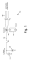
- FIG. 1 A schematic representation of a conventionally constructed motor vehicle electrical system is shown in Fig. 1.
- a generator 120, a battery 150 and a starter 110 are connected in parallel.
- the line length 130 between the generator 120 and the starter 110 on the one hand and the battery 150 on the other hand in each case about 1 m.
- Starter and generator are arranged on the engine block and connected to each other via a short cable. Due to variations in the current supplied by the generator and for the transmission of the starter current, the line cross-section is approximately 25 mm 2 .
- each load circuit 160 supplies power to one or more loads.
- these lines may have a smaller cross-section than the line 130, of about 5mm 2 .
- Typical current values of consumers in the vehicle electrical system range from about 1.5 A for parking light of all lights, 3 A for the brake light and flashing light, 8 A for the windscreen wiper and 8.5 A for Fog and headlights above 10 A for low beam and the interior fan an air conditioner, 18 A for the engine control with fuel pump and 20 A for the seat heating up to an electrical PTC heater with a power consumption in the range of about 100 A.
- All load circuits 160 are protected against a short circuit by an overcurrent protection device secured, so that the power supply to the respective load circuit interrupted becomes as soon as a short circuit occurs. This will cause thermal overheating prevents the cable and connector in the respective load circuit.
- the object of the invention is to provide an improved motor vehicle electrical system.
- a motor vehicle electrical system which has a generator, a battery, a capacitor of high capacity and a power distributor for the controllable supply of energy to load circuits of the motor vehicle.
- the generator, the battery and the high capacity capacitor are connected in parallel.
- the electrical connecting line between the battery and the power distributor has a cross section smaller than 10 mm 2 at a line length smaller than 2 m and a cross section smaller than 40 mm 2 at a line length greater than 2 m.
- the high-capacity capacitor is arranged in the power distributor. It then only the electrical connections between generator and the Capacitor or the starter and the capacitor for a higher current load be designed while the arrangement of the battery in the motor vehicle of the previous restrictions today's Bordnetze is free and arranged arbitrarily can be.
- the electrical connection line between the generator and the power distributor has a cross section smaller than 10 mm 2 , particularly preferably about 5 mm 2 .
- the connecting line between the battery and the power distributor has a maximum cross section of about 5 mm 2 at a maximum line length of 2 m, preferably 1 m.
- the battery can be arranged in the engine compartment of the motor vehicle, wherein a particularly low line cross-section can be used.
- the line length between the power distributor and the battery is a maximum of 4 m with a maximum cable cross-section of about 25 mm 2 .
- the battery can at this line length anywhere a vehicle, especially in the rear, are arranged, in comparison to a conventional cable cross-section of about 95 mm 2, only a cross-section of a maximum of about 25 mm 2 is required.
- FIG. 2 shows schematically the structure of an inventive Motor vehicle electrical network.
- a starter 110 and a generator 120 are separate Supply lines 120 connected to an electronic power distributor 210.
- the electronic power distributor is also a battery 150 via a supply line 240th connected.
- the generator 120 during operation of the automotive engine provides electrical power to the motor vehicle electrical system 200 stores the battery 150 during operation of the engine provided by the generator 120th Energy. To put the engine into operation, is via a chemical Reaction in the battery 150 generates electrical energy and supplied to the starter 110.
- the power distributor 210 controllably switches individual load circuits 230 to the Motor vehicle electrical system.
- the battery 150 can be positioned anywhere in the vehicle electrical system 200 according to the invention in the motor vehicle, without line connections must be used with large cable cross-sections.
- a feed line 130 having a length L Zul1 of approximately 1 m has a cross section of 25 mm 2
- the feed lines 220 according to the invention only have a cross-sectional area of approximately 5 mm 2 for the same length.
- the load circuits starting from the current distribution point have a cross section of 5 mm 2 for a length L Zul2 of approximately 1 m.
- the electrical connection of the battery to the power distribution point has a cross section of approximately 5 mm 2 at a maximum length L Zul3 of approximately 1 m.
- the battery is arranged with the Stromverteiltician in the rear of a motor vehicle.
- all connection lines to and from the power distribution point 140 or the battery 150 are considerably longer.
- the cable cross-sections must be increased in order to avoid heat generation in the lines with a larger line length with a correspondingly higher resistance.
- the cross section of the lines 130 conventionally increases from approximately 4 m to approximately 95 mm 2 at a length L Zul1 and the line cross section of the lines of the load circuits 160 increases to approximately 25 mm 2 at a length L Zul2 of up to approximately 5 m.
- these cross sections can be significantly reduced.
- the electronic power distributor 210 and the battery 150 are arranged spatially separated from each other.
- the buffer function exerted by a conventional battery is shifted into the electronic power distributor 210 to compensate for voltage fluctuations of the generator 120.
- all lines with a maximum length of about 1 m have a cross-section of the order of 5 mm 2 .
- a longer line connection between the electronic power distributor 210 and the battery 150 is required. Up to a length L Zul3 of about 4 m, the line cross-section is about 25 mm 2 .
- a further reduction of the cable cross-sections is dependent on the respective Application thereby possible that according to the invention an active current monitoring for controlling the fuse behavior in the power distributor 210 is carried out.
- the active monitoring of flowing in a load circuit 230 Stromes allowed, at a certain time behavior, especially at a rapid increase over a predetermined value to turn off the load circuit.
- the cross-section of conventional lines becomes regular the double rated current designed to short current peaks in the load circuit without thermal overload of the lines can handle.
- the inventive Current monitoring with the help of a microprocessor controlled control unit, the overload protection more precisely at short overload peaks and the short-circuit behavior adapt. This can in a simple way the cross section and thus the weight and the cost of the motor vehicle electrical system are reduced.
- the battery 150 is preferably in Rear of the vehicle arranged.
- the electronic power distributor 210 includes a plurality of semiconductor switches 410, the individual load circuits 412 controllable with the motor vehicle electrical system connect, i. turn a power supply to the individual load circuits on or off.
- semiconductor switches in particular semiconductor switches with a Smart power control used.
- Such a semiconductor switch for example the Building block 98 0268 of the company "International I.R. Rectifier" measures the connected in the Load circuit flowing current. In the specified semiconductor device becomes a current proportional to the measured current through a separate connection output. The current measured by each semiconductor switch 410 becomes supplied to a controller 440 of the electronic power distributor. This control, either within the electronic power distributor 210 or separately is arranged, monitors individually for each load circuit the permissible Electricity.
- the permissible current value for each load circuit is preferably for each load circuit 412 separately in the controller 440 adjustable. According to a preferred embodiment are 440 different current levels and different in the control "Trip" characteristics are provided which are separate for each load circuit 412 are selectable. As soon as the current measured for a load circuit 412 is the one for him exceeds the specified maximum value taking into account a permissible overcurrent, causes the controller 440 that the semiconductor switch 410, the electrical Connection breaks.
- the "intelligent" monitoring of the respective load current in the controller 440 allows allow short overcurrents, without the electrical connection to the Power supply to the load circuit is interrupted.
- the response can be designed individually, in particular to the function and the power requirements (and short-term overcurrent requirements) adapted to the respective load circuit become. It must short overcurrents when starting a motor or when switching of lamps, auxiliary heaters, etc. are taken into account.
- the protective function is intended to prevent overcurrents or short circuits in the Load circuits occur and cause a thermal overload of the lines and connectors.
- the thermal overload is converted by the Energy causes, i. Current height multiplied by the time for which the overcurrent is applied. It may well be ten times the rated current for one second to flow into a load circuit without any damage occurring.
- Such a Overcurrent must be recognized as unproblematic by the 440 controller.
- a fuse would be an interruption in such an overcurrent bring about and irreversible the current (until replacement of the fuse) interrupt.
- Short-term overcurrents with a multiple value of rated current occur, for example when switching on an electric motor.
- the rotor may initially be somewhat stiff or pinch, in particular at low ambient temperatures.
- An overcurrent that is several times of the rated current occurs for several 100 ms.
- electric PTC auxiliary heaters that for heating the air blown into the motor vehicle interior can be used within a time interval of approx. 10 seconds currents occur that correspond to twice the rated current. Due to the extremely short-term occurrence of such overcurrents, these are for the Cables and connectors unproblematic.
- a conventional fuse is usually on a An Anlagenstrom set greater than twice the rated current. Such a conventional one But fuse would also accept a permanent overcurrent that the 1.8 times the rated current.
- an electronic Hedge according to the present invention recognize such an overcurrent and after exceeding the time criterion, for example 10 seconds, interrupt the electrical connection.
- the respective load circuit can therefore be designed in its sizing to the actual rated current, so that the cable cross-sections and the connector do not double in the long run Rated current must be able to withstand.
- the control 440 according to the invention can also be achieved with the aid of an additional Adjust the temperature sensor to the current ambient temperature.
- the overcurrent detection and disconnection of a load circuit is therefore preferably temperature-dependent, according to a preferred Embodiment about a predetermined dependence between the applied Upper current limit and the determined ambient temperature.
- the controller may be a load circuit 412 also turn off depending on an external signal.
- the controller may be a load circuit 412 also turn off depending on an external signal. For example can disturbances in a load of a load circuit via separate Detected sensors and the danger emanating from these for the motor vehicle be banned prematurely.
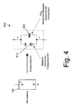
- FIG. 3 shows, by way of example only, a PTC heater 510 and a distributed power distributor 520 represented as a consumer.
- the decentralized power distributor 520 can via a plurality of semiconductor switches 525 also have subordinate load circuits switch off. These load circuits are only examples. For the expert it is of course, that every electrical consumer of a motor vehicle over such a load circuit 412 directly, or indirectly via a decentralized power distributor 520, is controllable.
- the electric power distributor 510 is a capacitor 400th high capacity provided in parallel to the generator 120 and the battery 150th is switched.
- the capacitor 400 has high capacitance values at low Volume.
- For a motor vehicle are preferably capacities in the area used from 450 to 600 F.
- double layer capacitors can even reach capacities up to several thousand F.
- Double-layer capacitors achieve a much higher energy density as aluminum electrolytic capacitors and a multiple higher power density as lead batteries. While in batteries the electrical energy is electrochemical is stored, the electrical energy in a capacitor is directly in Shape of positive or negative charges on the plates of the capacitor saved. There is no chemical reaction at the electrode surfaces required.
- Such double-layer capacitors for example double-layer capacitors
- the company EPCOS named "UltraCap” store electrical Energy and return it with high efficiency. In difference They can be charged and discharged without wear at very high currents become. In addition, they enable safe operation even at very low levels Temperatures and low voltage values. They give high performance without delay and very low loss at discharge currents up to 400 A from.
- a high capacitance capacitor 400 By the parallel connection of a high capacitance capacitor 400 to the Generator 120 and the starter battery 51 can achieve several advantages. For the boot process is no longer the battery 150 is responsible, but the high-performance capacitor 400. The capacitor 400 is before the startup process charged by the battery 150. Subsequently, the capacitor 400 gives the stored energy to the starter 110 from. The boot process can be safer be designed because the capacitor is capable of large amounts of energy even for a short time at low temperatures. In contrast, have Conventional motor vehicles at low temperatures often start problems because the chemical reactions taking place in the battery 150 do not cause large currents allow.
- the starting behavior can be further improved by increasing the energy stored in it without increasing the capacitance of the capacitor.
- a voltage converter 310 is connected between the battery 150 and the capacitor 400 in preparation for a starting operation.
- the voltage converter 310 converts the voltage 150 supplied by the battery into a higher voltage.
- the capacitor can absorb a much larger amount of energy at the same capacity.
- a breaker 320th connected parallel to the voltage converter 310 in the electrical connection between the battery 150 and the capacitor 400.
- the breaker disconnects the direct electrical connection between the Battery and the capacitor on, giving the capacitor a much higher Voltage can be supplied.
- the inventive device 300 with a voltage converter and a breaker can be the energy available for starting be increased significantly in a simple manner. A safe starting of the motor vehicle is then even with low battery with only low energy reserves still possible.
- the voltage converter (DC / DC converter) 310 is turned off and the electrical connection between the electric power distributor 210 and the battery 150 is made by the switch 320.
- the capacitor 400 is thus connected in parallel to the battery 150 and charged to the battery voltage U BATT .
- conventional electrical systems to a voltage of about 12.5 V, in future on-board networks to about 42 V.
- the voltage converter 310 activated while the switch 320 is opened.
- the electronic power distributor 210 individual load circuits switched off.
- load circuits 412 are switched off, the high Own power requirement.
- the shutdown can according to a particular embodiment via the controller 440 also as a function of the level of the battery voltage be made to start safely with low battery to ensure.
- the voltage converter now generates an output voltage that goes to the capacitor is applied, with the output voltage above the battery voltage lies.
- a battery voltage of 12.5 V is the increased output voltage for example, 16 V.
- the voltage is thus 3.5 V above the battery voltage and charges the capacitor accordingly higher. This is also the Energy stored in the condensate is about 60% higher than a conventional one Charging voltage of 12.5 V.
- the capacitor 400 always with a Voltage of 16 V charges, stands for the starting process always the same amount of energy available, regardless of the performance of the battery.
- the advantage achieved by the voltage converter can be increased either in Implement energy reserves for the starting process or to reduce the capacity of the capacitor. With the same stored amount of energy is then a small Capacitor 400 capacity sufficient for a safe startup.
- a further increase in the amount of energy in the condenser 400 can be achieved by a further increase of the charging voltage higher than 16 V in conventional electrical systems to reach.
- a limitation to a charging voltage of 16 V has the advantage that this increase no further complications with other electrical Components of the electrical system entails.
- the charging voltage of the capacitor 400 is therefore preferably on the design of the electrical components of On-board network and the dielectric strength of the capacitor itself oriented. at future on-board networks with a system voltage of 42 V, the capacitor can be charge to a significantly higher voltage, as far as a brief increase in voltage from the other electrical components coped without problems becomes.
- the charging of the capacitor takes place in good time before starting the starting process.
- multiple triggers be used.
- the driver can start charging, when the ignition key is inserted or the ignition switch in the position "Ignition ON" is brought.
- the charging process by opening a Vehicle door to be triggered. This can be the opening of any vehicle door as well as the opening of the driver's vehicle door detected and as a trigger signal be used for charging. If the vehicle door as a triggering event is used for the start of the recharging process, there is more time than during acquisition the ignition key position available.
- the capacitor 400 not only enables an improvement of the starting process, but can also take over the buffering effect of the conventional battery 150.
- An equivalent circuit diagram of a conventional battery 150 is shown in FIG.
- the equivalent circuit 600 of the battery 150 shows that the battery not only the Function of a chemical energy storage 610, but also the function of a Buffer capacitor 620 has. This capacitor effect results from the inner Structure of the lead-acid battery.
- the capacitor effect of a conventional battery has hitherto been used Smooth voltage fluctuations resulting from the generator 120.
- the generator 120 generates when the motor vehicle engine a three-phase current, which is rectified by means of diodes.
- the battery 150 is spatially arranged to be between the generator 150 and the loads in the load circuits 412.
- a low pass is formed from the combination of the battery capacity C Batt and the supply resistance of the electrical connection line between the generator 120 and the battery 150 R Zul1 .
- the low pass causes a smoothing of the voltage fluctuations of the current generated by the generator.
- this function is performed by the high capacity capacitor 400 accepted.
- While conventional electrical systems are designed so that on the electric Connecting lines between generator and battery high currents to compensate the voltage fluctuations can flow, according to the invention Function of energy storage and energy buffering of separate units perceived in the motor vehicle electrical system.
- the capacitor 400 takes over the buffering of voltage fluctuations, the battery 150 is the Energy ready for the starting process. This allows the battery in a simple manner away from the generator and the power distributor without the conventional effort for an electrical line connection 240 with the battery is required.
- the cross sections can, as an example related described with Fig. 2, be reduced to much smaller values. In order to Motor vehicle electrical systems are lighter and cheaper.
- the buffer function is achieved by the arrangement sequence generator - battery - power distribution - consumer in conjunction with the resulting low-pass filter.
- the low-pass filter is formed from the supply resistance R Zul1 between the generator and the battery on the one hand and the capacity C Batt of the battery on the other hand.
- the novel motor vehicle electrical system has a Variety of advantages over conventional electrical systems.
- the starter battery no longer takes over the start function, is a lower pulse and current load exposed, only reduced requirements with respect to the low-temperature behavior meet and can be a battery with reduced storage capacity be. With the help of a voltage transformer, the energy and thus the Increase start-up safety.
- the lines only have a smaller cross section so that cost and weight benefits are achieved, especially at the arrangement of the battery in the rear of the vehicle.
Landscapes
- Engineering & Computer Science (AREA)
- Power Engineering (AREA)
- Electric Propulsion And Braking For Vehicles (AREA)
- Control Of Charge By Means Of Generators (AREA)
- Charge And Discharge Circuits For Batteries Or The Like (AREA)
Priority Applications (8)
| Application Number | Priority Date | Filing Date | Title |
|---|---|---|---|
| EP04003414A EP1564863B1 (fr) | 2004-02-16 | 2004-02-16 | Réseau de bord d'un véhicule avec accumulation du courant de générateur indépendant de la batterie |
| DE502004005698T DE502004005698D1 (de) | 2004-02-16 | 2004-02-16 | Kraftfahrzeug-Bordnetz mit von der Batterie getrennter Pufferung des Generatorstroms |
| ES04003414T ES2295715T3 (es) | 2004-02-16 | 2004-02-16 | Circuito electrico para vehiculos con acumulacion de corriente del generador independiente de la bateria. |
| CNB200580005064XA CN100433499C (zh) | 2004-02-16 | 2005-02-02 | 带与发电机电流缓冲装置分开的蓄电池的机动车供电系统 |
| PCT/EP2005/001044 WO2005078891A1 (fr) | 2004-02-16 | 2005-02-02 | Reseau de bord de vehicule automobile a conservation du courant d'alternateur separee de la batterie |
| JP2006552508A JP2007522014A (ja) | 2004-02-16 | 2005-02-02 | ゼネレータ電流のバッテリ依存バッファリングを特徴とする自動車電気システム |
| KR1020067018417A KR100878033B1 (ko) | 2004-02-16 | 2005-02-02 | 발전기 전류의 배터리-독립형 버퍼링을 특징으로 하는자동차 전원 시스템 |
| US10/597,911 US20080224537A1 (en) | 2004-02-16 | 2005-02-02 | Motor Vehicle Supply System Featuring Battery-Independent Buffering of the Generator Current |
Applications Claiming Priority (1)
| Application Number | Priority Date | Filing Date | Title |
|---|---|---|---|
| EP04003414A EP1564863B1 (fr) | 2004-02-16 | 2004-02-16 | Réseau de bord d'un véhicule avec accumulation du courant de générateur indépendant de la batterie |
Publications (2)
| Publication Number | Publication Date |
|---|---|
| EP1564863A1 true EP1564863A1 (fr) | 2005-08-17 |
| EP1564863B1 EP1564863B1 (fr) | 2007-12-12 |
Family
ID=34684701
Family Applications (1)
| Application Number | Title | Priority Date | Filing Date |
|---|---|---|---|
| EP04003414A Expired - Lifetime EP1564863B1 (fr) | 2004-02-16 | 2004-02-16 | Réseau de bord d'un véhicule avec accumulation du courant de générateur indépendant de la batterie |
Country Status (8)
| Country | Link |
|---|---|
| US (1) | US20080224537A1 (fr) |
| EP (1) | EP1564863B1 (fr) |
| JP (1) | JP2007522014A (fr) |
| KR (1) | KR100878033B1 (fr) |
| CN (1) | CN100433499C (fr) |
| DE (1) | DE502004005698D1 (fr) |
| ES (1) | ES2295715T3 (fr) |
| WO (1) | WO2005078891A1 (fr) |
Cited By (3)
| Publication number | Priority date | Publication date | Assignee | Title |
|---|---|---|---|---|
| WO2007061634A3 (fr) * | 2005-11-17 | 2008-02-07 | Snap On Tools Corp | Dispositif et systeme d'entretien de vehicules alimentes par une source d'energie capacitive |
| WO2010078982A1 (fr) * | 2009-01-07 | 2010-07-15 | Robert Bosch Gmbh | Réseau de bord pour véhicule automobile équipé d'un système arrêt-démarrage |
| WO2016128375A1 (fr) * | 2015-02-11 | 2016-08-18 | Volkswagen Ag | Procédé de commande d'un récepteur d'un réseau de bord basse tension |
Families Citing this family (6)
| Publication number | Priority date | Publication date | Assignee | Title |
|---|---|---|---|---|
| DE102004036814B4 (de) * | 2004-07-29 | 2006-06-01 | Siemens Ag | Vorrichtung zur Versorgung einer Kraftstoffpumpe einer Brennkraftmaschine eines Kraftfahrzeuges mit elektrischem Strom |
| US20090200864A1 (en) * | 2008-02-12 | 2009-08-13 | Josef Maier | Chip on bus bar |
| JP5406574B2 (ja) * | 2008-12-17 | 2014-02-05 | ソニーモバイルコミュニケーションズ株式会社 | 電源装置および電子機器 |
| DE102010017417A1 (de) * | 2010-06-17 | 2011-12-22 | Dr. Ing. H.C. F. Porsche Aktiengesellschaft | Elektrisches Versorgungs- und Startsystem für ein Kraftfahrzeug und Verfahren zum Betrieb des elektrischen Versorgungs- und Startsystems |
| CN106160040B (zh) * | 2015-04-07 | 2021-01-29 | 低碳动能开发股份有限公司 | 车用二次锂电池 |
| DE102024204060B4 (de) * | 2024-04-30 | 2026-03-12 | Zf Friedrichshafen Ag | Sicherungsbox eines Fahrzeugs mit Überwachungseinrichtung |
Citations (3)
| Publication number | Priority date | Publication date | Assignee | Title |
|---|---|---|---|---|
| EP0376667A2 (fr) * | 1988-12-27 | 1990-07-04 | Isuzu Motors Limited | Alimentation électrique pour véhicules automobiles |
| US5642696A (en) * | 1995-01-17 | 1997-07-01 | Fuji Jukogyo Kabushiki Kaisha | Engine starting system for motor vehicle |
| WO2002066293A1 (fr) * | 2001-02-16 | 2002-08-29 | Siemens Aktiengesellschaft | Reseau de bord de vehicule automobile |
Family Cites Families (6)
| Publication number | Priority date | Publication date | Assignee | Title |
|---|---|---|---|---|
| US5175439A (en) * | 1987-12-21 | 1992-12-29 | Robert Bosch Gmbh | Power supply circuit for motor vehicles |
| US5256956A (en) * | 1988-12-27 | 1993-10-26 | Isuzu Motors Limited | Power supply apparatus for automotive vehicles |
| DE19742092A1 (de) * | 1997-09-24 | 1999-03-25 | Bosch Gmbh Robert | Elektrisch leitendes Kabel |
| DE19846319C1 (de) * | 1998-10-08 | 2000-02-17 | Daimler Chrysler Ag | Energieversorgungsschaltung für ein Kraftfahrzeugbordnetz mit zwei Spannungsversorgungszweigen |
| FR2808630B1 (fr) * | 2000-04-13 | 2002-10-25 | Peugeot Citroen Automobiles Sa | Circuit d'alimentation electrique a tension multiple pour vehicule automobile |
| FR2835106B1 (fr) * | 2002-01-24 | 2004-09-03 | Peugeot Citroen Automobiles Sa | Systeme d'alimentation en energie electrique d'un vehicule automobile |
-
2004
- 2004-02-16 DE DE502004005698T patent/DE502004005698D1/de not_active Expired - Lifetime
- 2004-02-16 EP EP04003414A patent/EP1564863B1/fr not_active Expired - Lifetime
- 2004-02-16 ES ES04003414T patent/ES2295715T3/es not_active Expired - Lifetime
-
2005
- 2005-02-02 US US10/597,911 patent/US20080224537A1/en not_active Abandoned
- 2005-02-02 KR KR1020067018417A patent/KR100878033B1/ko not_active Expired - Fee Related
- 2005-02-02 WO PCT/EP2005/001044 patent/WO2005078891A1/fr not_active Ceased
- 2005-02-02 CN CNB200580005064XA patent/CN100433499C/zh not_active Expired - Fee Related
- 2005-02-02 JP JP2006552508A patent/JP2007522014A/ja active Pending
Patent Citations (3)
| Publication number | Priority date | Publication date | Assignee | Title |
|---|---|---|---|---|
| EP0376667A2 (fr) * | 1988-12-27 | 1990-07-04 | Isuzu Motors Limited | Alimentation électrique pour véhicules automobiles |
| US5642696A (en) * | 1995-01-17 | 1997-07-01 | Fuji Jukogyo Kabushiki Kaisha | Engine starting system for motor vehicle |
| WO2002066293A1 (fr) * | 2001-02-16 | 2002-08-29 | Siemens Aktiengesellschaft | Reseau de bord de vehicule automobile |
Non-Patent Citations (1)
| Title |
|---|
| DIPL.-ING. HORST BAUER: "Autoelektrik, Autoelektronik, 4. Auflage", 31 October 2002, ROBERT BOSCH GMBH, STUTTGART, XP002288350 * |
Cited By (4)
| Publication number | Priority date | Publication date | Assignee | Title |
|---|---|---|---|---|
| WO2007061634A3 (fr) * | 2005-11-17 | 2008-02-07 | Snap On Tools Corp | Dispositif et systeme d'entretien de vehicules alimentes par une source d'energie capacitive |
| WO2010078982A1 (fr) * | 2009-01-07 | 2010-07-15 | Robert Bosch Gmbh | Réseau de bord pour véhicule automobile équipé d'un système arrêt-démarrage |
| WO2016128375A1 (fr) * | 2015-02-11 | 2016-08-18 | Volkswagen Ag | Procédé de commande d'un récepteur d'un réseau de bord basse tension |
| US10479299B2 (en) | 2015-02-11 | 2019-11-19 | Volkswagen Aktiengesellschaft | Method for controlling a consumer of a low-voltage on-board electrical system |
Also Published As
| Publication number | Publication date |
|---|---|
| JP2007522014A (ja) | 2007-08-09 |
| KR20070009999A (ko) | 2007-01-19 |
| DE502004005698D1 (de) | 2008-01-24 |
| WO2005078891A1 (fr) | 2005-08-25 |
| US20080224537A1 (en) | 2008-09-18 |
| EP1564863B1 (fr) | 2007-12-12 |
| KR100878033B1 (ko) | 2009-01-13 |
| ES2295715T3 (es) | 2008-04-16 |
| CN100433499C (zh) | 2008-11-12 |
| CN1918768A (zh) | 2007-02-21 |
Similar Documents
| Publication | Publication Date | Title |
|---|---|---|
| EP1564862B2 (fr) | Réseau de bord d'un véhicule avec un transformateur de tension | |
| EP1600337B1 (fr) | Coupe-circuit électronique pour batterie | |
| EP2232672B1 (fr) | Montage électrique pour stabiliser la tension d'un réseau de bord | |
| DE102017203851B4 (de) | Elektrische Sicherung, Verfahren zum Betreiben einer elektrischen Sicherung und elektrisches Traktionsnetz | |
| DE19954306B4 (de) | Vorrichtung zur elektrischen Energieerzeugnung mit einer Brennstoffzelle in einem Fahrzeug und Verfahren zum Betrieb einer derartigen Vorrichtung | |
| DE102012222208B4 (de) | Verfahren zum gesteuerten Verbinden mehrerer Bordnetzzweige eines Fahrzeugs, Steuereinheit zur Ausführung des Verfahrens sowie Bordnetz | |
| EP3022433B1 (fr) | Disposition d'interrupteur dans un circuit de bord de véhicule à moteur | |
| EP3022432B1 (fr) | Coupe-circuit électronique de sécurité pour véhicules à moteur | |
| EP2471155B1 (fr) | Système d'accumulation d'énergie électrique | |
| DE102007026164A1 (de) | Elektrisches Versorgungssystem für ein Kraftfahrzeug | |
| DE102014203030A1 (de) | Verfahren zum gesteuerten Verbinden mehrerer Bordnetzzweige eines Fahrzeugs, Steuereinheit zur Ausführung des Verfahrens sowie Fahrzeugbordnetz | |
| EP2953227A1 (fr) | Réseau de bord pour un véhicule automobile | |
| WO2013160031A1 (fr) | Réseau électrique de bord d'un véhicule automobile comprenant au moins deux sous-réseaux | |
| EP1564863B1 (fr) | Réseau de bord d'un véhicule avec accumulation du courant de générateur indépendant de la batterie | |
| DE10231517B4 (de) | Bordnetz für ein Kraftfahrzeug | |
| DE10262000B4 (de) | Bordnetz für ein Kraftfahrzeug | |
| EP2840253B1 (fr) | Réseau de bord pour un véhicule automobile et véhicule avec un tel réseau de bord | |
| EP3720733B1 (fr) | Procédé de commande d'une installation électrique d'un véhicule à moteur à entraînement électrique, dotée de plusieurs batteries et installation électrique d'un véhicule à entraînement électrique | |
| EP1564077A1 (fr) | Distributeur de courant éléctronique pour un réseau de bord d'un véhicule automobile | |
| EP2469070B1 (fr) | Limitation de l'introduction de la tension de démarrage dans un réseau de bord de véhicule automobile | |
| EP1044852B1 (fr) | Réseau de bord pour véhicules | |
| WO2013182385A1 (fr) | Réseau de bord de véhicule à moteur, présentant une machine électrique et au moins deux accumulateurs d'énergie à tensions de charge différentes, et procédé pour son fonctionnement | |
| DE102020207892A1 (de) | Verfahren zum Überwachen der Energieversorgung eines Kraftfahrzeugs | |
| DE10324250B4 (de) | Spannungsversorgungssystem für sicherheitsrelevante elektrische Verbraucher | |
| DE102013009991A1 (de) | Fremdstartfähige Integration einer Batterie in ein Kraftfahrzeug-Bordnetz |
Legal Events
| Date | Code | Title | Description |
|---|---|---|---|
| PUAI | Public reference made under article 153(3) epc to a published international application that has entered the european phase |
Free format text: ORIGINAL CODE: 0009012 |
|
| AK | Designated contracting states |
Kind code of ref document: A1 Designated state(s): AT BE BG CH CY CZ DE DK EE ES FI FR GB GR HU IE IT LI LU MC NL PT RO SE SI SK TR |
|
| AX | Request for extension of the european patent |
Extension state: AL LT LV MK |
|
| 17P | Request for examination filed |
Effective date: 20060210 |
|
| AKX | Designation fees paid |
Designated state(s): DE ES FR IT SE |
|
| 17Q | First examination report despatched |
Effective date: 20060327 |
|
| GRAP | Despatch of communication of intention to grant a patent |
Free format text: ORIGINAL CODE: EPIDOSNIGR1 |
|
| GRAS | Grant fee paid |
Free format text: ORIGINAL CODE: EPIDOSNIGR3 |
|
| GRAA | (expected) grant |
Free format text: ORIGINAL CODE: 0009210 |
|
| AK | Designated contracting states |
Kind code of ref document: B1 Designated state(s): DE ES FR IT SE |
|
| REF | Corresponds to: |
Ref document number: 502004005698 Country of ref document: DE Date of ref document: 20080124 Kind code of ref document: P |
|
| REG | Reference to a national code |
Ref country code: ES Ref legal event code: FG2A Ref document number: 2295715 Country of ref document: ES Kind code of ref document: T3 |
|
| PG25 | Lapsed in a contracting state [announced via postgrant information from national office to epo] |
Ref country code: SE Free format text: LAPSE BECAUSE OF FAILURE TO SUBMIT A TRANSLATION OF THE DESCRIPTION OR TO PAY THE FEE WITHIN THE PRESCRIBED TIME-LIMIT Effective date: 20080312 |
|
| ET | Fr: translation filed | ||
| PLBE | No opposition filed within time limit |
Free format text: ORIGINAL CODE: 0009261 |
|
| STAA | Information on the status of an ep patent application or granted ep patent |
Free format text: STATUS: NO OPPOSITION FILED WITHIN TIME LIMIT |
|
| 26N | No opposition filed |
Effective date: 20080915 |
|
| REG | Reference to a national code |
Ref country code: FR Ref legal event code: PLFP Year of fee payment: 13 |
|
| PGFP | Annual fee paid to national office [announced via postgrant information from national office to epo] |
Ref country code: DE Payment date: 20160218 Year of fee payment: 13 Ref country code: ES Payment date: 20160223 Year of fee payment: 13 |
|
| PGFP | Annual fee paid to national office [announced via postgrant information from national office to epo] |
Ref country code: FR Payment date: 20160222 Year of fee payment: 13 |
|
| REG | Reference to a national code |
Ref country code: DE Ref legal event code: R082 Ref document number: 502004005698 Country of ref document: DE Representative=s name: GRUENECKER PATENT- UND RECHTSANWAELTE PARTG MB, DE Ref country code: DE Ref legal event code: R081 Ref document number: 502004005698 Country of ref document: DE Owner name: EBERSPAECHER CONTROLS LANDAU GMBH & CO. KG, DE Free format text: FORMER OWNER: CATEM DEVELEC GMBH, 76863 HERXHEIM, DE |
|
| REG | Reference to a national code |
Ref country code: ES Ref legal event code: PC2A Owner name: EBERSPAECHER CONTROLS LANDAU GMBH & CO. KG Effective date: 20161122 |
|
| REG | Reference to a national code |
Ref country code: FR Ref legal event code: CA Effective date: 20161208 Ref country code: FR Ref legal event code: CD Owner name: EBERSPACHER CONTROLS LANDAU GMBH & CO. KG, DE Effective date: 20161208 Ref country code: FR Ref legal event code: CJ Effective date: 20161208 |
|
| PGFP | Annual fee paid to national office [announced via postgrant information from national office to epo] |
Ref country code: IT Payment date: 20170217 Year of fee payment: 14 |
|
| REG | Reference to a national code |
Ref country code: DE Ref legal event code: R119 Ref document number: 502004005698 Country of ref document: DE |
|
| REG | Reference to a national code |
Ref country code: FR Ref legal event code: ST Effective date: 20171031 |
|
| PG25 | Lapsed in a contracting state [announced via postgrant information from national office to epo] |
Ref country code: FR Free format text: LAPSE BECAUSE OF NON-PAYMENT OF DUE FEES Effective date: 20170228 Ref country code: DE Free format text: LAPSE BECAUSE OF NON-PAYMENT OF DUE FEES Effective date: 20170901 |
|
| REG | Reference to a national code |
Ref country code: ES Ref legal event code: FD2A Effective date: 20180622 |
|
| PG25 | Lapsed in a contracting state [announced via postgrant information from national office to epo] |
Ref country code: ES Free format text: LAPSE BECAUSE OF NON-PAYMENT OF DUE FEES Effective date: 20170217 |
|
| PG25 | Lapsed in a contracting state [announced via postgrant information from national office to epo] |
Ref country code: IT Free format text: LAPSE BECAUSE OF NON-PAYMENT OF DUE FEES Effective date: 20180216 |