EP1564881A2 - Regelvorrichtung für bürstenlosen Motor mit Überhitzungsschutzfunktion - Google Patents
Regelvorrichtung für bürstenlosen Motor mit Überhitzungsschutzfunktion Download PDFInfo
- Publication number
- EP1564881A2 EP1564881A2 EP05002835A EP05002835A EP1564881A2 EP 1564881 A2 EP1564881 A2 EP 1564881A2 EP 05002835 A EP05002835 A EP 05002835A EP 05002835 A EP05002835 A EP 05002835A EP 1564881 A2 EP1564881 A2 EP 1564881A2
- Authority
- EP
- European Patent Office
- Prior art keywords
- brushless motor
- phase
- current
- electric power
- motor
- Prior art date
- Legal status (The legal status is an assumption and is not a legal conclusion. Google has not performed a legal analysis and makes no representation as to the accuracy of the status listed.)
- Granted
Links
Images


Classifications
-
- H—ELECTRICITY
- H02—GENERATION; CONVERSION OR DISTRIBUTION OF ELECTRIC POWER
- H02P—CONTROL OR REGULATION OF ELECTRIC MOTORS, ELECTRIC GENERATORS OR DYNAMO-ELECTRIC CONVERTERS; CONTROLLING TRANSFORMERS, REACTORS OR CHOKE COILS
- H02P21/00—Arrangements or methods for the control of electric machines by vector control, e.g. by control of field orientation
- H02P21/06—Rotor flux based control involving the use of rotor position or rotor speed sensors
-
- H—ELECTRICITY
- H02—GENERATION; CONVERSION OR DISTRIBUTION OF ELECTRIC POWER
- H02P—CONTROL OR REGULATION OF ELECTRIC MOTORS, ELECTRIC GENERATORS OR DYNAMO-ELECTRIC CONVERTERS; CONTROLLING TRANSFORMERS, REACTORS OR CHOKE COILS
- H02P29/00—Arrangements for regulating or controlling electric motors, appropriate for both AC and DC motors
- H02P29/02—Providing protection against overload without automatic interruption of supply
Definitions
- This invention relates to a brushless motor control apparatus, and more specifically, to a method for preventing a brushless motor from overheating.
- temperature protective devices such as a thermistor and a thermal fuse are attached and the temperature rise is suppressed by limiting currents flowing in the windings in response to winding temperatures or cutting off currents when they exceed a predetermined temperature.
- overheat protection needs addition of a thermistor, a thermal fuse, etc. and addition of a peripheral circuit for detection. This causes increase in cost.
- winding temperatures are estimated from a motor current value squared and a motor resistance value, and the current is limited according to the estimated temperature because the winding temperature is proportional to a product of the motor current value squared by the motor resistance value.
- the brushless motor uses three-phase alternating currents. Consequently its accurate state cannot be grasped, except that the sampling period and calculation period of current, voltage, etc. are done at high speed. In a worst case, it is likely that calculation results may be different from actual values depending on the sampling period (for example, only low current values of the alternating waveform are sampled), and hence dielectric breakdown may occur due to a failure of the overheat protection.
- a motor current waveform becomes an alternating waveform of a period of 3.75 ms. That is, if this alternating waveform is intended to be sampled accurately and subjected to calculation, it must be performed in a period of a few hundreds of micro seconds or less, which increases a calculation load of a microcomputer. To prevent the calculation load in the microcomputer from increasing, a microcomputer capable of high-speed processing is necessitated. This will result in an increase of cost.
- JP 2003-164185A it is also proposed in JP 2003-164185A to realize the overheat protection by using a q-axis current that is a torque component current of the brushless motor, or both the q-axis current and a d-axis current that is an exciting component current while preventing increase in cost and calculation load.
- the brushless motor is driven by the three-phase alternating currents.
- Each of its voltage, current, magnetic flux, etc. is represented by a composite vector that is a vector sum of components generated by alternating components of each phase.
- its control is simplified by converting the three-phase alternating currents that necessitate handling these vectors to two-axis direct currents.
- This two-axis direct current conversion means conversion whereby a motor having a fixed part and a rotating part is converted to one in an orthogonal coordinate system whose coordinates are both fixed, i.e., a rotating orthogonal coordinate system, and is called d-q conversion.
- the q-axis is in advance of the d-axis by a phase of ⁇ /2 and the d-axis is orientated in a direction of a magnetic flux formed by a field magnet.
- a field magnet circuit is formed with permanent magnets or by flowing constant field-magnet currents in field-magnet windings.
- an armature current is supplied in a rotor conductor from the outside, whereby a torque proportional to the armature current can be generated. Therefore, the direct current motor is rotated with the torque proportional to the armature current.
- the rotor is not electrically connected with the outside. That is, only a primary current flowing in the stator generates both a rotating magnetic field and an induction current equivalent to the armature current. Therefore, the primary current contains both a current (exciting component current) that generates a secondary interlinkage flux crossing a secondary-side rotor and a current (torque component current) that flows in a secondary-side conductor.
- the magnitude and phase of a current determines the torque of the brushless motor, the alternating current motor, or the like.
- the current is divided into a current component (magnetic flux current) that forms a magnetic flux in the direction of a main magnetic flux established inside the motor and a current component with a phase advanced by 90° that controls the torque directly (torque current).
- the two components are controlled independently.
- the magnetic flux current and the torque current are defined as a current component that forms a magnetic field in the d-axis direction and a current component that forms a magnetic field in the q-axis direction, respectively.
- the fact that each of the current, voltage, and magnetic flux is controlled after being divided into a d-axis component and a q-axis component may account for a name of the vector control.
- These current components can be calculated by the well known three-phase to two-phase conversion based on a rotation angle ⁇ of the main magnetic flux to the stator in the d-q axis coordinate system.
- the use of the d-axis current in addition to the q-axis current enables estimation with higher accuracy than that of an estimation only with the q-axis current, although it adds a slight increase in the calculation load.
- the brushless motor uses the three-phase alternating currents, when the motor is in rotation or when the motor is not in rotation and yet predetermined currents are flowing through it so as to produce a torque (motor lock state), currents applied to phase windings might differ largely among them even if the q-axis current or the d-axis current is the same. The current also might differ depending on a motor locking position (electrical angle).
- a brushless motor control apparatus calculates electric power or energy produced in a brushless motor based on a q-axis current, and protects the brushless motor or a motor control unit based on the magnitude of the electric power.
- the use of the q-axis current for overheat protection makes it possible to employ a technique of overheat protection of the direct current motor.
- the use of the q-axis current which hardly varies unlike the three-phase current varying periodically, enables the sampling period to be made longer.
- the brushless motor control apparatus detects the electrical angle of the brushless motor, and calculates the electric power produced in the brushless motor when it makes rotation equivalent to one cycle period of the electrical angle.
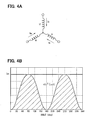
- FIG. 4A shows schematically the windings of the brushless motor.
- Currents flowing in U-phase, V-phase and W-phase windings are represented by lu, lv and lw.
- the peak value of theses phase currents are represented by Im, respectively.
- lu, lv and lw are expressed as follows.
- lw lm ⁇ sin ( ⁇ t - 4 ⁇ /3)
- the electric power Wa, Wb, and Wc that are produced in the respective phase windings are expressed as follows.
- the electric power produced in the brushless motor when it makes rotation corresponding to one cycle period of the electrical angle can be used as references. Since the q-axis current is used as a current whereby the electric power is calculated, this construction makes it possible to calculate the produced electric power accurately and prevent an increase in calculation load.
- the brushless motor control apparatus uses a predetermined coefficient for setting a predetermined value for overheat protection.
- This predetermined coefficient takes different values in two states: when the brushless motor is energized but not rotated; and when the brushless motor is energized and rotated.
- the d-axis current i d becomes zero and the q-axis current i q becomes ⁇ (3/2) ⁇ Im.
- a current applied to each phase winding may change also with the locking position (electrical angle).
- the use of information on the rotation state of the motor and the position of the rotor enables to reduce estimation errors considerably and avoid excessive or too little overheat protections, and also enables to prevent both increase in the cost resulting from additional parts and increase in the calculation load resulting from the use of the phase current.
- the brushless motor control apparatus can be applied to electronic power steering apparatus of vehicles whereby a brushless motor is driven on energization and assisting steering torque is given to a steering mechanism triggered by driver's steering operations.
- the brushless motor control apparatus uses the q-axis current, which is a torque component current of the brushless motor and is conventionally proposed, or both the q-axis current and a d-axis current, which is an exciting component current. It additionally uses information on the rotation state of the motor and the position of the rotor (electrical angle). This enables estimation errors to be reduced considerably and the same effect as is given by a method of estimation calculation of the motor winding temperatures using the phase current to be obtained.
- FIG. 1 A brushless motor control apparatus is shown in FIG. 1.
- Reference numeral 1 denotes a brushless motor
- numeral 2 denotes a rotation angle sensor, such as a well known resolver for detecting electrical angle
- numeral 3 denotes a controller
- numeral 4 denotes a current sensor.
- the controller 3 comprises a drive circuit 31, a PWM conversion unit 32, a two-phase to three-phase conversion circuit 33, a three-phase to two-phase conversion circuit 34, a d-axis PI control unit 35 and a q-axis PI control unit 36 that perform well known PI (Proportional and Integral) control, subtraction circuits 37 and 38, an instruction value arithmetic unit 39, an electrical angle arithmetic unit 61, an angular velocity arithmetic unit 64, and an overheat protection arithmetic unit 65, wherein a construction except for the overheat protection arithmetic unit 65 is the same as that of a known brushless motor control apparatus.
- the controller 3 includes a known microcomputer with an internal A/D (analog/digital) converter. The controller 3 may however be constructed with an exclusive hardware circuit.
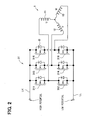
- the drive circuit 31 includes a three-phase inverter circuit as shown in FIG. 2.
- Reference numerals 311-316 denote MOS power transistors, symbol D a flywheel diode, numeral 311 a U-phase upper arm element, numeral 312 a U-phase lower arm element, numeral 313 a V-phase upper arm element, numeral 314 a V-phase lower arm element, numeral 315 a W-phase upper arm element, and numeral 316 a W-phase lower arm element, wherein each of the elements 311-316 is connected to the flywheel diode D in reverse parallel individually.
- a battery voltage is applied through an unillustrated smoothing circuit, and three-phase alternating voltages outputted from the drive circuit 31 (namely, a three-phase inverter) are applied to each end of a U-phase winding 11, a V-phase winding 12 and a W-phase winding 13 of the motor 1, individually.
- the electrical angle arithmetic unit 61 generates a rotation angle signal ⁇ from an analog rotation angle signal outputted from the rotation angle sensor, and outputs it to both the two-phase to three-phase conversion circuit 33 and the three-phase to two-phase conversion circuit 34.
- the controller 3 performs PWM control of the three-phase brushless motor 1 based on the above phase current, the rotation angle signal and a torque instruction value externally applied.
- the three-phase to two-phase conversion circuit 34 converts the applied three-phase current lu, lv and lw into the q-axis current and the d-axis current based on the rotation angle signal ⁇ t outputted from the rotation angle sensor 2.
- the instruction value arithmetic unit 39 converts the torque instruction value externally applied into a q-axis current instruction value.
- the subtraction circuit 38 performs PI conversion of a difference ⁇ i q between the q-axis current i q and the q-axis current instruction value i qc in the q-axis PI control unit 36, and outputs it to the two-phase to three-phase conversion circuit 33.
- the subtraction circuit 37 performs PI conversion of a difference ⁇ i d between the d-axis current i d and the d-axis current instruction value i dc in the d-axis PI control unit 35, and outputs it to the two-phase to three-phase conversion circuit 33.
- the two-phase to three-phase conversion circuit 33 converts PI control quantities of ⁇ i q and ⁇ i d applied from the d-axis PI control unit 35 and the q-axis PI control unit 36, respectively, based on the rotation angle signal outputted from the rotation angle sensor 2 to target three-phase voltages Vu, Vv and Vw (phase voltage instruction value) through two-phase to three-phase conversion, and outputs them to the PWM conversion unit 32.
- the PWM conversion unit 32 outputs PWM signals, i.e., PWMU, PWMV and PWMW, each of which has a duty ratio corresponding to the applied target three-phase voltages Vu, Vv and Vw to the MOS power transistors 311-316 of the drive circuit 31.
- the drive circuit 31 drives the motor 1 by outputting the three-phase alternating voltages Vu, Vv and Vw to the motor 1.
- Each of PWMU, PWMV and PWMW of the PWM signals includes two PWM signals having mutually opposite signs.
- the PWM signals include six signals (gate voltages) of a PWMU upper signal, a PWMU lower signal, a PWMV upper signal, a PWMV lower signal, a PWMW upper signal and a PWMW lower signal.
- each of the phase current of the U-phase, V-phase and W-phase windings of the motor 1 is detected by the current sensor 4 (S1), and subsequently the electrical angle ⁇ t is calculated in the electrical angle arithmetic unit 61 based on the rotation angle of the motor 1 detected by the rotation angle sensor 2 (S2). Then, the kwon three-phase to two-phase conversion is performed using the formula 3 based on the phase current values detected in the three-phase to two-phase conversion unit 34 to obtain the q-axis current i q (S3).
- the angular velocity is calculated in the angular velocity arithmetic unit 64 (S4) based on the rotation angle of the motor 1 detected by the rotation angle sensor 2.
- the angular velocity can be calculated from a change in the rotation angle per unit time.
- the overheat protection arithmetic unit 65 first, multiplies a squared value of the q-axis current i q by a previously stored electric resistance r of each phase winding of the motor 1 to calculate the most recent basic electric power Po of the phase winding resulting from the q-axis current i q (S5).
- a product obtained by multiplying the most recent basic electric power Po calculated previously by the coefficient obtained in the above is specified as the most recent electric power P (S9).
- the most recent value P is added to stored past history data of electric power and this history data is substituted into a previously stored calculation formula to calculate the temperature T of the phase winding (S10).
- the overheat protection arithmetic unit 65 sends a predetermined signal to the instruction value arithmetic unit 39.
- the instruction value arithmetic unit 39 receives the signal and sends a value for reducing the current flowing in the motor 1, i.e., a value that is smaller than the q-axis current instruction value and calculated according to the torque instruction value, to the subtraction circuit 38 as a q-axis current instruction value (S12).
- the brushless motor control apparatus 3 is also suitable for an electronic power steering (EPS) apparatus of vehicles.
- FIG. 6 is an outline block diagram of an electronic power steering apparatus 101 to which the brushless motor control apparatus 3 is applied.
- a steering wheel 110 is coupled to a steering shaft 112a and the lower end of this steering shaft 112a is coupled to a torque sensor 111 for detecting a movement of the steering wheel 110 by a driver.
- the upper end of a pinion shaft 112b is coupled to the torque sensor 111.
- a pinion (not illustrated) is provided on the lower end of the pinion shaft 112b, and this pinion is engaged with a rack bar 118 in a steering gear box 116.
- each tie rod 120 is coupled to each end of the rack bar 118, respectively.
- the other end of the each tie rod 120 is coupled to a steering wheel 124 through a knuckle arm 122.
- an electric motor 115 that is the three-phase brushless motor is attached to the pinion shaft 112b through gears (not illustrated). A method of attaching the electric motor 115 to the rack bar 118 coaxially may be adopted.
- a steering control unit 130 is equipped with a known CPU 131, RAM 132, ROM 133, an I/O 134 serving as an input and output interface, and a bus line 135 connecting these components.
- the CPU 131 performs control with a program and data stored in the ROM 133 and the RAM 132.
- the ROM 133 has a program storage area 133a and a data storage area 133b.
- the program storage area 133a stores an EPS control program 133p.
- the data storage area 133b stores data necessary for operations of the EPS control program 133p.
- the steering control unit 130 calculates a drive torque that corresponds to the torque detected by the torque sensor 111 and should be produced by the electric motor 115, and makes a motor driver 114 apply a voltage for producing the calculated drive torque to the electric motor 115.
- a resolver 109 detects a rotation angle of the electric motor 115 and a current sensor 108 detects a current flowing in the electric motor 115, whereby the apparatus checks whether the motor is rotating that corresponds to the drive torque and calculates a voltage to be applied to the electric motor 115 according to the result.
- this electronic power steering apparatus detects a current flowing in the electric motor 115 with the current sensor 108, subsequently calculates a voltage to be applied to the electric motor 115 and performs control for driving the electric motor 115 in the construction shown in FIG. 1 and FIG. 2.
- the vehicle may travel with the steering wheel 110 maintained at a fixed angle. This corresponds to the motor lock state described above.
- the rotation state of the electric motor 115 changes quickly depending on operation states of the steering wheel 110 or driving conditions. That is, by applying the brushless motor control apparatus, appropriate overheat protection that is responsive to operation states of the steering wheel 110 can be realized with excessive or too little overheat protections being avoided.
Landscapes
- Engineering & Computer Science (AREA)
- Power Engineering (AREA)
- Control Of Motors That Do Not Use Commutators (AREA)
- Control Of Ac Motors In General (AREA)
- Power Steering Mechanism (AREA)
Applications Claiming Priority (2)
| Application Number | Priority Date | Filing Date | Title |
|---|---|---|---|
| JP2004033206A JP4379702B2 (ja) | 2004-02-10 | 2004-02-10 | ブラシレスモータ制御装置 |
| JP2004033206 | 2004-02-10 |
Publications (3)
| Publication Number | Publication Date |
|---|---|
| EP1564881A2 true EP1564881A2 (de) | 2005-08-17 |
| EP1564881A3 EP1564881A3 (de) | 2009-12-23 |
| EP1564881B1 EP1564881B1 (de) | 2018-05-30 |
Family
ID=34697872
Family Applications (1)
| Application Number | Title | Priority Date | Filing Date |
|---|---|---|---|
| EP05002835.6A Expired - Lifetime EP1564881B1 (de) | 2004-02-10 | 2005-02-10 | Regelvorrichtung für bürstenlosen Motor mit Überhitzungsschutzfunktion |
Country Status (3)
| Country | Link |
|---|---|
| US (1) | US7102314B2 (de) |
| EP (1) | EP1564881B1 (de) |
| JP (1) | JP4379702B2 (de) |
Cited By (3)
| Publication number | Priority date | Publication date | Assignee | Title |
|---|---|---|---|---|
| WO2008132449A1 (en) * | 2007-04-26 | 2008-11-06 | Trw Limited | Electric power steering |
| US10574173B2 (en) | 2016-09-02 | 2020-02-25 | Kongsberg Inc. | Techniques for limiting electrical current provided to a motor in an electric power steering system |
| CN111075738A (zh) * | 2019-12-05 | 2020-04-28 | 上海英恒电子有限公司 | 一种基于无刷电机的风扇启动控制方法和控制装置 |
Families Citing this family (31)
| Publication number | Priority date | Publication date | Assignee | Title |
|---|---|---|---|---|
| JP2005224075A (ja) * | 2004-02-09 | 2005-08-18 | Sanyo Electric Co Ltd | インバータ装置 |
| US7053587B2 (en) * | 2004-02-10 | 2006-05-30 | Denso Corporation | Apparatus for controlling three-phase AC motor on two-phase modulation technique |
| JP4379702B2 (ja) * | 2004-02-10 | 2009-12-09 | 株式会社デンソー | ブラシレスモータ制御装置 |
| DE602006012350D1 (de) | 2005-11-09 | 2010-04-01 | Toyota Motor Co Ltd | Batteriezustand-diagnosevorrichtung |
| JP2007181330A (ja) * | 2005-12-28 | 2007-07-12 | Jtekt Corp | モータ制御装置および制御方法 |
| DE102006006032A1 (de) * | 2006-02-09 | 2007-08-23 | Siemens Ag | Verfahren und Vorrichtung zum Betreiben einer Synchronmaschine |
| JP4228237B2 (ja) * | 2006-06-06 | 2009-02-25 | トヨタ自動車株式会社 | 電動パワーステアリング装置 |
| JP2008067556A (ja) * | 2006-09-11 | 2008-03-21 | Sanyo Electric Co Ltd | モータ制御装置 |
| JP5114914B2 (ja) * | 2006-10-03 | 2013-01-09 | 日産自動車株式会社 | インバータ制御装置 |
| JP5098323B2 (ja) * | 2006-12-18 | 2012-12-12 | 株式会社ジェイテクト | 電気式動力舵取装置 |
| JP5194608B2 (ja) * | 2007-07-26 | 2013-05-08 | トヨタ自動車株式会社 | 回転電機制御装置 |
| JP5453729B2 (ja) * | 2008-04-14 | 2014-03-26 | 株式会社ジェイテクト | モータ制御装置および電動パワーステアリング装置 |
| JP5297126B2 (ja) * | 2008-09-11 | 2013-09-25 | 本田技研工業株式会社 | 電動パワーステアリング装置 |
| JP2011200105A (ja) * | 2010-02-26 | 2011-10-06 | Denso Corp | 回転機の制御装置 |
| US9119655B2 (en) | 2012-08-03 | 2015-09-01 | Stryker Corporation | Surgical manipulator capable of controlling a surgical instrument in multiple modes |
| US9921712B2 (en) | 2010-12-29 | 2018-03-20 | Mako Surgical Corp. | System and method for providing substantially stable control of a surgical tool |
| CN103036529B (zh) | 2011-09-29 | 2017-07-07 | 株式会社大亨 | 信号处理装置、滤波器、控制电路、逆变器和转换器系统 |
| DK2575252T3 (en) | 2011-09-29 | 2018-10-08 | Daihen Corp | Signal processor, filter, power converter for power converter circuit, connection inverter system and PWM inverter system |
| US8662620B2 (en) | 2011-11-21 | 2014-03-04 | Xerox Corporation | Indirect temperature monitoring for thermal control of a motor in a printer |
| US9226796B2 (en) | 2012-08-03 | 2016-01-05 | Stryker Corporation | Method for detecting a disturbance as an energy applicator of a surgical instrument traverses a cutting path |
| US9820818B2 (en) | 2012-08-03 | 2017-11-21 | Stryker Corporation | System and method for controlling a surgical manipulator based on implant parameters |
| CA2879414A1 (en) | 2012-08-03 | 2014-02-06 | Stryker Corporation | Systems and methods for robotic surgery |
| AT514494B1 (de) * | 2013-06-24 | 2015-04-15 | Bernecker & Rainer Ind Elektronik Gmbh | Verfahren zur Funktionsprüfung einer Haltebremse eines Elektromotors |
| JP6096718B2 (ja) * | 2014-06-13 | 2017-03-15 | ファナック株式会社 | 複数のptcサーミスタを備えた電動機の過熱検出装置 |
| JP2016146693A (ja) * | 2015-02-06 | 2016-08-12 | トヨタ自動車株式会社 | 過負荷保護装置 |
| JP6508021B2 (ja) * | 2015-12-04 | 2019-05-08 | トヨタ自動車株式会社 | モータ温度推定装置 |
| JP6634954B2 (ja) * | 2016-05-11 | 2020-01-22 | 株式会社デンソー | モータ制御装置 |
| US10715077B2 (en) | 2016-11-01 | 2020-07-14 | Nissan Motor Co., Ltd. | Method of controlling motor and device of controlling motor |
| WO2018112025A1 (en) | 2016-12-16 | 2018-06-21 | Mako Surgical Corp. | Techniques for modifying tool operation in a surgical robotic system based on comparing actual and commanded states of the tool relative to a surgical site |
| WO2023170740A1 (ja) * | 2022-03-07 | 2023-09-14 | 三菱電機株式会社 | 電力変換器の過熱保護制御装置 |
| CN119543713B (zh) * | 2025-01-22 | 2025-04-22 | 陕西拓普达精密设备有限公司 | 永磁直流无刷无槽电机的控制方法及系统 |
Family Cites Families (38)
| Publication number | Priority date | Publication date | Assignee | Title |
|---|---|---|---|---|
| US4169990A (en) * | 1974-06-24 | 1979-10-02 | General Electric Company | Electronically commutated motor |
| JPS61180592A (ja) * | 1985-02-05 | 1986-08-13 | Mitsubishi Electric Corp | 査導電動機の制御装置 |
| JPH03139192A (ja) * | 1989-10-23 | 1991-06-13 | Mitsubishi Electric Corp | 電動機制御装置 |
| GB2239112B (en) * | 1989-11-13 | 1993-12-08 | Mitsubishi Electric Corp | Brushless motor and an axial flow fan with the brushless motor |
| JP2934345B2 (ja) * | 1991-09-06 | 1999-08-16 | 三菱電機株式会社 | 誘導電動機の制御装置 |
| DE4132881A1 (de) * | 1991-10-03 | 1993-07-29 | Papst Motoren Gmbh & Co Kg | Ansteuerschaltung fuer buerstenlose gleichstrommotoren |
| US5521482A (en) * | 1993-06-29 | 1996-05-28 | Liberty Technologies, Inc. | Method and apparatus for determining mechanical performance of polyphase electrical motor systems |
| JP3297159B2 (ja) * | 1993-09-14 | 2002-07-02 | 東芝キヤリア株式会社 | 直流ブラシレスモータの駆動装置およびその良否識別方法 |
| US5570256A (en) * | 1994-03-15 | 1996-10-29 | Siemens Energy & Automation, Inc. | Induction machine protection device |
| US5586043A (en) * | 1994-12-05 | 1996-12-17 | General Electric Company | Method and apparatus for monitoring differentials between signals |
| US5760556A (en) * | 1996-01-26 | 1998-06-02 | General Electric Company | Motor controller and protector unit |
| JPH104694A (ja) * | 1996-04-15 | 1998-01-06 | Matsushita Electric Ind Co Ltd | ブラシレスモータの保護装置 |
| JP3908805B2 (ja) * | 1996-06-20 | 2007-04-25 | ブラザー工業株式会社 | モータの温度制御装置 |
| WO1998011663A1 (fr) * | 1996-09-13 | 1998-03-19 | Hitachi, Ltd. | Dispositif de commande de moteur a induction et procede de commande dudit dispositif |
| JPH10201210A (ja) * | 1997-01-10 | 1998-07-31 | Zexel Corp | ブラシレスモータ |
| JP3488043B2 (ja) * | 1997-05-26 | 2004-01-19 | 株式会社日立製作所 | 永久磁石型同期発電機を備えた駆動システム及びそれを用いた電気車の駆動制御方法 |
| JP3527071B2 (ja) * | 1997-07-04 | 2004-05-17 | 株式会社日立製作所 | 電気自動車の制御装置 |
| JP3991416B2 (ja) * | 1998-01-23 | 2007-10-17 | 日本精工株式会社 | 電動パワーステアリング装置の制御装置 |
| JP3484968B2 (ja) * | 1998-02-24 | 2004-01-06 | 日本精工株式会社 | 電動パワーステアリング装置の制御装置 |
| JP2000287493A (ja) * | 1999-03-30 | 2000-10-13 | Matsushita Electric Ind Co Ltd | モータの保護装置 |
| JP4093678B2 (ja) * | 1999-05-11 | 2008-06-04 | 三菱電機株式会社 | 電動機制御装置 |
| US6198241B1 (en) * | 1999-07-07 | 2001-03-06 | Westinghouse Air Brake Company | Motor protection for a powered door system |
| BR9904253A (pt) * | 1999-09-20 | 2001-06-26 | Brasil Compressores Sa | Método de controle e proteção de motores elétricos, sistema de controle de motor elétrico e sistema de motor elétrico |
| EP1364453A1 (de) * | 2001-02-08 | 2003-11-26 | Stridsberg Innovation AB | Hochzuverlässiges motorsystem |
| DE10119201A1 (de) * | 2001-04-19 | 2002-10-24 | Bsh Bosch Siemens Hausgeraete | Verfahren und Vorrichtung zum Messen der Wicklungstemperatur eines Antriebsmotors |
| US6900607B2 (en) * | 2001-08-17 | 2005-05-31 | Delphi Technologies, Inc. | Combined feedforward and feedback parameter estimation for electric machines |
| JP4019873B2 (ja) * | 2001-10-12 | 2007-12-12 | 日産自動車株式会社 | 舵角比制御装置 |
| JP2003125588A (ja) * | 2001-10-12 | 2003-04-25 | Mitsubishi Electric Corp | 電力変換装置 |
| JP2003164185A (ja) * | 2001-11-27 | 2003-06-06 | Denso Corp | 三相交流モータ制御装置 |
| US7088565B2 (en) * | 2002-04-12 | 2006-08-08 | Denso Corporation | Load drive control apparatus with performances of power-consumption reduction and overheat protection |
| US6741047B2 (en) * | 2002-06-28 | 2004-05-25 | Sunonwealth Electric Machine Industry Co., Ltd. | Dual current-limiting circuit for DC brushless motor |
| US6895176B2 (en) * | 2002-09-12 | 2005-05-17 | General Electric Company | Method and apparatus for controlling electronically commutated motor operating characteristics |
| JP4170054B2 (ja) * | 2002-09-19 | 2008-10-22 | 日本サーボ株式会社 | 保護回路を備えたdcブラシレスモータの制御回路 |
| US6822839B2 (en) * | 2002-12-05 | 2004-11-23 | Eaton Corporation | Method and apparatus of detecting internal motor faults in an induction machine |
| JP3966194B2 (ja) * | 2003-03-17 | 2007-08-29 | 株式会社デンソー | モータ制御装置 |
| JP4269941B2 (ja) * | 2004-01-08 | 2009-05-27 | 株式会社日立製作所 | 風力発電装置およびその制御方法 |
| JP4455075B2 (ja) * | 2004-01-28 | 2010-04-21 | 三菱電機株式会社 | モータ制御装置 |
| JP4379702B2 (ja) * | 2004-02-10 | 2009-12-09 | 株式会社デンソー | ブラシレスモータ制御装置 |
-
2004
- 2004-02-10 JP JP2004033206A patent/JP4379702B2/ja not_active Expired - Fee Related
-
2005
- 2005-02-08 US US11/053,030 patent/US7102314B2/en not_active Expired - Lifetime
- 2005-02-10 EP EP05002835.6A patent/EP1564881B1/de not_active Expired - Lifetime
Cited By (3)
| Publication number | Priority date | Publication date | Assignee | Title |
|---|---|---|---|---|
| WO2008132449A1 (en) * | 2007-04-26 | 2008-11-06 | Trw Limited | Electric power steering |
| US10574173B2 (en) | 2016-09-02 | 2020-02-25 | Kongsberg Inc. | Techniques for limiting electrical current provided to a motor in an electric power steering system |
| CN111075738A (zh) * | 2019-12-05 | 2020-04-28 | 上海英恒电子有限公司 | 一种基于无刷电机的风扇启动控制方法和控制装置 |
Also Published As
| Publication number | Publication date |
|---|---|
| JP4379702B2 (ja) | 2009-12-09 |
| US20050174090A1 (en) | 2005-08-11 |
| JP2005229661A (ja) | 2005-08-25 |
| EP1564881A3 (de) | 2009-12-23 |
| EP1564881B1 (de) | 2018-05-30 |
| US7102314B2 (en) | 2006-09-05 |
Similar Documents
| Publication | Publication Date | Title |
|---|---|---|
| EP1564881B1 (de) | Regelvorrichtung für bürstenlosen Motor mit Überhitzungsschutzfunktion | |
| US9248852B2 (en) | Electric power steering system | |
| US9692342B2 (en) | Brushless motor and motor control device | |
| JP5365701B2 (ja) | 電動パワーステアリング装置 | |
| JP5130031B2 (ja) | 永久磁石モータの位置センサレス制御装置 | |
| US8766577B2 (en) | Three-phase rotary machine control apparatus | |
| CN106330035B (zh) | 旋转电机控制装置 | |
| US9407177B2 (en) | Rotating electric machine control device and electric power steering apparatus | |
| EP1612927A1 (de) | Motorantriebssteuereinrichtung und elektrische servolenkeinrichtung damit | |
| US9548688B2 (en) | Motor control apparatus | |
| US10960919B2 (en) | Control device and electric power steering device using same | |
| JP2012166776A (ja) | 電動パワーステアリング装置 | |
| US10243489B2 (en) | Rotary electric machine control apparatus and electric power steering apparatus using the same | |
| JP5406226B2 (ja) | 電動パワーステアリング装置 | |
| CN110890856B (zh) | 用于三相旋转机械设备的控制装置 | |
| JP7317249B2 (ja) | 回転電機の制御装置及び電動パワーステアリング装置 | |
| JP5263079B2 (ja) | 電動パワーステアリング装置 | |
| JP2009017707A (ja) | モータ制御装置 | |
| JP5257374B2 (ja) | 電動パワーステアリング装置 | |
| JP2011131643A (ja) | 電動パワーステアリング装置 | |
| JP2021118582A (ja) | モータ制御装置、電動アクチュエータ製品及び電動パワーステアリング装置 | |
| JP2011230531A (ja) | モータ制御装置 | |
| JP2008284977A (ja) | 電動パワーステアリング制御装置、及びモータ駆動制御方法 | |
| JP2024125628A (ja) | モータ制御装置およびモータ制御方法 | |
| JP5287698B2 (ja) | 電動パワーステアリング装置 |
Legal Events
| Date | Code | Title | Description |
|---|---|---|---|
| PUAI | Public reference made under article 153(3) epc to a published international application that has entered the european phase |
Free format text: ORIGINAL CODE: 0009012 |
|
| AK | Designated contracting states |
Kind code of ref document: A2 Designated state(s): AT BE BG CH CY CZ DE DK EE ES FI FR GB GR HU IE IS IT LI LT LU MC NL PL PT RO SE SI SK TR |
|
| AX | Request for extension of the european patent |
Extension state: AL BA HR LV MK YU |
|
| PUAL | Search report despatched |
Free format text: ORIGINAL CODE: 0009013 |
|
| AK | Designated contracting states |
Kind code of ref document: A3 Designated state(s): AT BE BG CH CY CZ DE DK EE ES FI FR GB GR HU IE IS IT LI LT LU MC NL PL PT RO SE SI SK TR |
|
| AX | Request for extension of the european patent |
Extension state: AL BA HR LV MK YU |
|
| AKY | No designation fees paid | ||
| 17P | Request for examination filed |
Effective date: 20100618 |
|
| RBV | Designated contracting states (corrected) |
Designated state(s): DE FR GB |
|
| 17Q | First examination report despatched |
Effective date: 20120914 |
|
| GRAP | Despatch of communication of intention to grant a patent |
Free format text: ORIGINAL CODE: EPIDOSNIGR1 |
|
| STAA | Information on the status of an ep patent application or granted ep patent |
Free format text: STATUS: GRANT OF PATENT IS INTENDED |
|
| INTG | Intention to grant announced |
Effective date: 20171211 |
|
| RIN1 | Information on inventor provided before grant (corrected) |
Inventor name: HAYASHI, YOSHITAKA |
|
| GRAS | Grant fee paid |
Free format text: ORIGINAL CODE: EPIDOSNIGR3 |
|
| GRAA | (expected) grant |
Free format text: ORIGINAL CODE: 0009210 |
|
| STAA | Information on the status of an ep patent application or granted ep patent |
Free format text: STATUS: THE PATENT HAS BEEN GRANTED |
|
| AK | Designated contracting states |
Kind code of ref document: B1 Designated state(s): DE FR GB |
|
| REG | Reference to a national code |
Ref country code: GB Ref legal event code: FG4D |
|
| REG | Reference to a national code |
Ref country code: DE Ref legal event code: R096 Ref document number: 602005054024 Country of ref document: DE |
|
| RIC2 | Information provided on ipc code assigned after grant |
Ipc: H02P 21/00 20160101ALI20050616BHEP Ipc: H02P 7/00 20160101AFI20050616BHEP |
|
| REG | Reference to a national code |
Ref country code: DE Ref legal event code: R097 Ref document number: 602005054024 Country of ref document: DE |
|
| PLBE | No opposition filed within time limit |
Free format text: ORIGINAL CODE: 0009261 |
|
| STAA | Information on the status of an ep patent application or granted ep patent |
Free format text: STATUS: NO OPPOSITION FILED WITHIN TIME LIMIT |
|
| 26N | No opposition filed |
Effective date: 20190301 |
|
| PGFP | Annual fee paid to national office [announced via postgrant information from national office to epo] |
Ref country code: FR Payment date: 20230220 Year of fee payment: 19 |
|
| PGFP | Annual fee paid to national office [announced via postgrant information from national office to epo] |
Ref country code: GB Payment date: 20230220 Year of fee payment: 19 Ref country code: DE Payment date: 20230216 Year of fee payment: 19 |
|
| REG | Reference to a national code |
Ref country code: DE Ref legal event code: R119 Ref document number: 602005054024 Country of ref document: DE |
|
| GBPC | Gb: european patent ceased through non-payment of renewal fee |
Effective date: 20240210 |
|
| PG25 | Lapsed in a contracting state [announced via postgrant information from national office to epo] |
Ref country code: DE Free format text: LAPSE BECAUSE OF NON-PAYMENT OF DUE FEES Effective date: 20240903 |
|
| PG25 | Lapsed in a contracting state [announced via postgrant information from national office to epo] |
Ref country code: GB Free format text: LAPSE BECAUSE OF NON-PAYMENT OF DUE FEES Effective date: 20240210 |
|
| PG25 | Lapsed in a contracting state [announced via postgrant information from national office to epo] |
Ref country code: FR Free format text: LAPSE BECAUSE OF NON-PAYMENT OF DUE FEES Effective date: 20240229 |
|
| PG25 | Lapsed in a contracting state [announced via postgrant information from national office to epo] |
Ref country code: GB Free format text: LAPSE BECAUSE OF NON-PAYMENT OF DUE FEES Effective date: 20240210 Ref country code: FR Free format text: LAPSE BECAUSE OF NON-PAYMENT OF DUE FEES Effective date: 20240229 Ref country code: DE Free format text: LAPSE BECAUSE OF NON-PAYMENT OF DUE FEES Effective date: 20240903 |