EP1564923A1 - Vorrichtung und Verfahren zur Kontrollinformationsübertragung in einem Mobilkommunikationssystem - Google Patents
Vorrichtung und Verfahren zur Kontrollinformationsübertragung in einem Mobilkommunikationssystem Download PDFInfo
- Publication number
- EP1564923A1 EP1564923A1 EP20050002948 EP05002948A EP1564923A1 EP 1564923 A1 EP1564923 A1 EP 1564923A1 EP 20050002948 EP20050002948 EP 20050002948 EP 05002948 A EP05002948 A EP 05002948A EP 1564923 A1 EP1564923 A1 EP 1564923A1
- Authority
- EP
- European Patent Office
- Prior art keywords
- data
- pilot
- signal
- ack
- channel
- Prior art date
- Legal status (The legal status is an assumption and is not a legal conclusion. Google has not performed a legal analysis and makes no representation as to the accuracy of the status listed.)
- Withdrawn
Links
Images


Classifications
-
- H—ELECTRICITY
- H04—ELECTRIC COMMUNICATION TECHNIQUE
- H04L—TRANSMISSION OF DIGITAL INFORMATION, e.g. TELEGRAPHIC COMMUNICATION
- H04L1/00—Arrangements for detecting or preventing errors in the information received
- H04L1/12—Arrangements for detecting or preventing errors in the information received by using return channel
- H04L1/16—Arrangements for detecting or preventing errors in the information received by using return channel in which the return channel carries supervisory signals, e.g. repetition request signals
- H04L1/1607—Details of the supervisory signal
- H04L1/1692—Physical properties of the supervisory signal, e.g. acknowledgement by energy bursts
-
- H—ELECTRICITY
- H04—ELECTRIC COMMUNICATION TECHNIQUE
- H04L—TRANSMISSION OF DIGITAL INFORMATION, e.g. TELEGRAPHIC COMMUNICATION
- H04L1/00—Arrangements for detecting or preventing errors in the information received
- H04L1/12—Arrangements for detecting or preventing errors in the information received by using return channel
- H04L1/16—Arrangements for detecting or preventing errors in the information received by using return channel in which the return channel carries supervisory signals, e.g. repetition request signals
- H04L1/1607—Details of the supervisory signal
- H04L1/1671—Details of the supervisory signal the supervisory signal being transmitted together with control information
-
- H—ELECTRICITY
- H04—ELECTRIC COMMUNICATION TECHNIQUE
- H04L—TRANSMISSION OF DIGITAL INFORMATION, e.g. TELEGRAPHIC COMMUNICATION
- H04L1/00—Arrangements for detecting or preventing errors in the information received
- H04L1/12—Arrangements for detecting or preventing errors in the information received by using return channel
- H04L1/16—Arrangements for detecting or preventing errors in the information received by using return channel in which the return channel carries supervisory signals, e.g. repetition request signals
- H04L1/18—Automatic repetition systems, e.g. Van Duuren systems
- H04L1/1803—Stop-and-wait protocols
-
- H—ELECTRICITY
- H04—ELECTRIC COMMUNICATION TECHNIQUE
- H04L—TRANSMISSION OF DIGITAL INFORMATION, e.g. TELEGRAPHIC COMMUNICATION
- H04L25/00—Baseband systems
- H04L25/02—Details ; arrangements for supplying electrical power along data transmission lines
- H04L25/0202—Channel estimation
- H04L25/0224—Channel estimation using sounding signals
- H04L25/0228—Channel estimation using sounding signals with direct estimation from sounding signals
-
- H—ELECTRICITY
- H04—ELECTRIC COMMUNICATION TECHNIQUE
- H04L—TRANSMISSION OF DIGITAL INFORMATION, e.g. TELEGRAPHIC COMMUNICATION
- H04L1/00—Arrangements for detecting or preventing errors in the information received
- H04L1/0001—Systems modifying transmission characteristics according to link quality, e.g. power backoff
- H04L1/0002—Systems modifying transmission characteristics according to link quality, e.g. power backoff by adapting the transmission rate
- H04L1/0003—Systems modifying transmission characteristics according to link quality, e.g. power backoff by adapting the transmission rate by switching between different modulation schemes
Definitions
- the present invention relates to an apparatus and a method for transmitting control information representing whether or not uplink packet data are received in a mobile communication system. More particularly, the present invention relates to an apparatus and a method for transmitting control information without using a separate channel or code.
- an international mobile telecommunication ('IMT')-2000 standard enabling transmission of voice and high speed data has been developed from an IS-95 standard mainly transmitting/receiving a voice signal.
- the IMT-2000 standard targets a voice service, a dynamic image service and an Internet search service of high quality.
- the mobile communication system includes various schemes for providing information such as voice, data, etc.
- the representative scheme is a high speed downlink packet access ('HSDPA') scheme in a universal mobile terrestrial system (UMTS) communication system.
- 'HSDPA' high speed downlink packet access
- UMTS universal mobile terrestrial system
- an HSDPA scheme is the general term for data transmission schemes using high speed-downlink shared channels ('HS-DSCHs'), which are downlink data channels for supporting high speed downlink packet data transmission, and control channels relating to the HS-DSCHs.
- 'HS-DSCHs' high speed-downlink shared channels
- 'AMC' adaptive modulation and coding
- 'HARQ' hybrid automatic retransmission request
- 'FCS' fast cell select
- the HARQ scheme has employed the following two methods to improve the transmission efficiency of an automatic retransmission request (ARQ) scheme: one method is to perform a retransmission request and response between a user equipment ('UE') and a node B; and the other method is to enable a UE to temporarily store data having an error, combine the stored data with retransmission data of the corresponding data (data having the error), and decode the combined data.
- ARQ automatic retransmission request
- the next packet data are transmitted only after an ACK for previous packet data are received.
- the next packet data are transmitted only after the ACK for the previous packet data are received in this way, there may occur a case in which current packet data are not transmitted before the ACK for the previous packet data is received.
- n-channel SAW HARQ scheme a plurality of packet data are continuously transmitted without receiving the ACK for the previous packet data, so that the use efficiency of a channel can be improved. That is, n logical channels capable of being distinguished from each other by a specific time or a channel number are set between a UE and a node B.
- the UE receiving packet data recognizes a channel through which the received packet data have been transmitted and performs necessary processing for the received packet data. For instance, the UE restructures the packet data according to a sequence by which the packet data must be received or performs a soft combining for the packet data.
- the following tables 1 and 2 show physical channels used in a downlink and an uplink of a mobile communication system.
- Downlink Physical channel Function DPDCH Dedicated physical data channel
- DPCCH Dedicated physical control channel
- CPICH Common pilot channel P-CCPCH Primary common control physical channel
- S-CCPCH Second common control physical channel SCH Synchronization channel
- PDSCH Physical downlink shared channel
- AICH Acquisition indicator channel AP-AICH Access preamble acquisition indicator channel
- PICH Paging indicator channel CSICH CPCH(common packet channel) status indicator channel CD/CA-ICH CPCH collision detection/channel assignment indicator channel
- HS-PDSCH High speed-physical downlink shared control channel
- HS-SCCH High speed-shared control channel
- DPCCH Dedicated physical control channel
- PRACH Physical random access channel
- PCPCH Physical common packet channel
- the downlink physical channels are distinguished from each other by means of orthogonal variable spreading factors ('OVSFs') code.
- 'OVSFs' orthogonal variable spreading factors
- a scheme similar to a scheme for supporting a packet data service through a downlink may be introduced to support a packet data service through an uplink. That is, similar to a downlink, a stop and wait automatic retransmission request (SAW ARQ) scheme and the n-channel SAW HARQ scheme may be introduced.
- SAW ARQ stop and wait automatic retransmission request
- a scheme for transmitting control information ('ACK/NACK information') regarding whether or not the packet data have been received without an error by means of a downlink will be described.
- the scheme for transmitting the ACK/NACK information by means of the downlink may be classified into a time multiplexing scheme and a code multiplexing scheme.
- the time multiplexing scheme will be described with reference to FIG. 1 and the code multiplexing scheme will be described with reference to FIG. 2.
- FIG. 1 shows the downlink physical channel.
- the kind and the functions of the downlink physical channels are as shown in table 1.
- the ACK/NACK information is time-multiplexed in a space obtained by puncturing the data of the physical channel and is then transmitted. That is, the physical channel transports the ACK/NACK information contained in a predetermined interval in which data are not transmitted.
- FIG. 2 is a view illustrating a process by which code-multiplexed ACK/NACK information is transmitted through the downlink physical channel.
- a separate physical channel for transmitting the ACK/NACK information is generated in addition to the conventional physical channel transporting data, and the ACK/NACK information is transmitted through the generated physical channel.
- the conventional physical channel and the physical channel for transmitting the ACK/NACK information are distinguished from each other by the OVSF code as described above. Further, the physical channel for transmitting the ACK/NACK information may contain control information indicating an ACK/NACK information transmission channel.
- the present invention has been made to solve the above-mentioned problems occurring in the prior art, and it an object of the present invention to provide an apparatus and a method for transmitting control information for packet data without using a separate channel.
- a method for transmitting information regarding whether data are received in a mobile communication system comprising generating a pilot signal having different predetermined pilot patterns according to whether the data are received and the data contain an error, and inserting the generated pilot signal into a pilot field of a physical channel frame as control information and transmitting the physical channel frame.
- a method for transmitting information regarding whether or not data are received in a mobile communication system comprising detecting a pilot signal that was inserted into a pilot field of a physical channel frame as control information for the transmitted data, and determining whether the data are received and the data contain an error based on a pilot pattern of the detected pilot signal, and determining whether the data are retransmitted based on a result of the determination.
- an apparatus for receiving information regarding whether transmitted data are received in a mobile communication system comprises a pilot pattern generator for generating a pilot signal having different predetermined pilot patterns according to whether the data are received and the data contain an error, a pilot pattern inserting unit for inserting the selected pilot signal into a pilot field of a physical channel frame as control information, and a modulator for modulating and transmitting the physical channel frame.
- an apparatus for receiving information regarding whether transmitted data are received in a mobile communication system comprises a channel estimator for detecting a pilot signal that was inserted into a pilot field of a physical channel frame as control information for the transmitted data, and a packet channel adjuster for determining whether the data are received and the data contain an error by a pilot pattern of the detected pilot signal and determining whether the data are retransmitted by a result of the checking.
- the present invention provides a scheme for transmitting/receiving control information by means of a symbol/bit pattern of a conventional pilot channel without transmitting the control information by means of a separate code or time.
- the present invention discloses three embodiments.
- the first embodiment provides a scheme for transmitting an ACK/NACK as control information through the pilot field of a dedicated physical channel ('DPCH').
- the second embodiment provides a scheme for using the pilot field of a DPCH as a reference for supporting a beamforming and simultaneously transmitting an ACK/NACK as control information through the pilot field.
- the third embodiment provides a scheme for transmitting an ACK/NACK/MISS as control information according to the generation of an orthogonal pattern set. In the third embodiment, only a method for transmitting the ACK/NACK/MISS as the control information will be described. Further, in addition to the ACK/NACK/MISS, other control information can also be transmitted without departing from the scope of the present invention.
- the first embodiment proposed by the present invention relates to a method for transmitting ACK/NACK information through a phase modulation for the pilot field of an existing downlink DPCH.
- a phase reference of a dedicated channel is a common control channel (CPICH).
- the downlink dedicated physical channel (DPCH) which is a dedicated channel, is transmitted after a dedicated physical control channel (DPCCH) (i.e., control channel) and a dedicated physical data channel (DPDCH) (i.e., data channel) are time-multiplexed.
- DPCCH dedicated physical control channel
- DPDCH dedicated physical data channel
- the phase reference of the dedicated channel has been transmitted through the DPCCH. That is, a pilot field capable of being used as a reference for supporting a dedicated channel estimation and a beam forming for channel compensation has been transmitted through the DPCCH.
- a CPICH replaces the role of the pilot field.
- FIG. 3 is a block diagram illustrating the structure of a transmitter for transmitting ACK/NACK information according to the first embodiment of the present invention.
- the transmitter includes a DPDCH generator 300, a DPCCH generator 302, a mutiplexer 304, a pilot bit inserting unit 306, a modulator 308, a pilot bit generator 312, an ACK/NACK information converter 314 and a multiplier 310.
- a node B having received uplink packet data from a UE demodulates the received data.
- the node B analyzes whether the received data contain an error and generates ACK/NACK information.
- the node B When the received data contain an error, the node B generates NACK information requesting retransmission of the packet data.
- the node B when the received data does not contain an error, the node B generates ACK information which does not request the retransmission of the packet data.
- the generated ACK/NACK information is transmitted to the ACK/NACK information converter 314.
- the ACK/NACK information converter 314 generates a specific ACK/NACK signal according to the received ACK/NACK information. That is, when the received information is the ACK information, the ACK/NACK information converter 314 generates a signal having a value of +1. In contrast, when the received information is the NACK information, the ACK/NACK information converter 314 generates a signal having a value of -1.
- the ACK/NACK signal generated according to the received information may have different values by a user's selection. That is, in another embodiment, when the received information is the ACK information, the ACK/NACK information converter 314 may generate -1. In contrast, when the received information is the NACK information, the ACK/NACK information converter 314 may generate +1.
- the ACK/NACK information converter 314 outputs +1 as a basic value and generates -1 when the received ACK/NACK information is the ACK information.
- the reason for setting the basic value of the ACK/NACK information converter 314 as +1 is that it is necessary to satisfy the condition proposed by the conventional standard when the ACK/NACK information is not transmitted.
- the ACK/NACK information converter 314 outputs the generated ACK/NACK signal to the multiplier 310.
- the pilot bit generator 312 generates a pilot signal having a predetermined pilot pattern.
- the generated pilot pattern is defined by a 3 rd Generation Partnership Project (3GPP) standard TS25.211. However, it is clear that the embodiments of the present invention can easily employ other pilot patterns.
- the generated pilot signal is sent to the multiplier 310.
- the multiplier 310 performs a multiplication for the received pilot signal and the ACK/NACK signal transmitted from the ACK/NACK information converter 314.
- the following equation 1 represents an operation performed by the multiplier 310.
- the S i (n) is an output signal of the multiplier 310
- the A(i) is an ACK signal or an NACK signal (i.e., +1 or -1) transmitted from the ACK/NACK information converter 314 corresponding to a 1 th slot
- the p i (n) is a pilot signal of a downlink DPCH corresponding to an i th slot
- the n is a slot index representing time slots of a physical channel and is classified into pilot fields representing slots including a pilot signal and other fields.
- the multiplier 310 outputs "0".
- the pilot signal containing the ACK/NACK information which is an output of the multiplier 310, is transmitted to the pilot bit inserting unit 306.
- the DPDCH generator 300 generates DPDCH data by means of a received dedicated channel ('DCH') and transmits the generated DPDCH data to the mutiplexer 304.
- the DPCCH generator 302 generates DPCCH data by means of transmit power control ('TPC') information of a DPDCH and a transport format combination indicator ('TFCI'), and transmits the generated DPCCH data to the mutiplexer 304.
- the mutiplexer 304 transmits DPCH data obtained by multiplexing the received DPDCH data and DPCCH data to the pilot bit inserting unit 306.
- the pilot bit inserting unit 306 outputs a DPCH frame obtained by time-multiplexing the signal transmitted from the multiplier 310 with the DPCH data.
- the time-multiplexed DPCH frame is modulated by the modulator 308 and is then sent through a transmission antenna.
- FIG. 4 is a block diagram showing the structure of a receiver according to the first embodiment of the present invention.
- Data transmitted through a DPDCH and control signals transmitted through a DPCCH may be demodulated through each separate path.
- a processing path concern object
- ACK/NACK information is processed
- the DPCH signal transmitted from the transmitter is demodulated and is then sent to a channel compensator 400.
- the received signal that experienced a channel compensation process in the channel compensator 400 is modulated by a modulator 402. Further, the received signal that experienced channel compensation in the channel compensator 400 is sent to an ACK/NACK extractor 404.
- the ACK/NACK extractor 404 extracts ACK/NACK information from the pilot signal contained in the received signal. The detailed structure of the ACK/NACK extractor 404 will be described with reference to FIG. 5 later.
- the ACK/NACK information extracted by the ACK/NACK extractor 404 is sent to a packet channel adjuster 406.
- the packet channel adjuster 406 determines whether the previously transmitted uplink packet data are retransmitted according to the received ACK/NACK information.
- the pilot signal is extracted after the channel compensator 400.
- a pilot signal extracted before the channel compensator 400 may be used in order to perform a channel estimation. That is, in this embodiment of the present invention, the pilot signal used for determination of an ACK/NACK may be extracted at any position regardless of a channel compensation process. Those who are skilled in the art can easily construct the receiver regardless of extracted positions of the pilot signal.
- FIG. 5 is a block diagram showing the structure of the ACK/NACK extractor 404 according to the first embodiment of the present invention.
- the ACK/NACK extractor 404 includes a DPCH reception judgment unit 502, a DPCH pilot extractor 500, a DPCH pilot field pattern detector 504 and an ACK/NACK judgment unit 506.
- a DPCH reception judgment unit 502 a DPCH pilot extractor 500
- a DPCH pilot field pattern detector 504 a DPCH pilot field pattern detector 504
- ACK/NACK judgment unit 506 the structure of the ACK/NACK extractor 404 will be described in detail with reference to FIG. 5.
- the DPCH reception judgment unit 502 determines whether a channel to be currently received is a DPCH.
- a current time time slot
- a processing result i.e., ACK/NACK information
- the DPCH pilot extractor 500 extracts only a pilot field component of the DPCH signal from the reception signal which is an output of the channel compensator 400 and outputs the extracted pilot field component to the DPCH pilot field pattern detector 504.
- the following equation 2 represents the signal transmitted to the DPCH pilot field pattern detector 504.
- the DPCH pilot field pattern detector 504 detects a pilot field pattern of a DPCH signal as shown in equation 2 by means of a slot format of a DPCH and a slot number in one frame of a DPCH being currently demodulated.
- the slot number in one frame and a pilot pattern corresponding to the slot number are defined by a 3GPP standard TS25.211. However, it is clear that the embodiments of the present invention can easily employ pilot patterns different from the above pilot pattern.
- the following equation 3 represents a signal output from the DPCH pilot field pattern detector 504. wherein the N pilot represents the number of pilot symbols contained in a pilot field, the N start represents a start symbol index of the pilot field, the N end represents the last symbol index of the pilot field and the
- a component capable of having a sign is the A(i).
- the ACK/NACK detection unit 506 determines whether the previously transmitted uplink packet data are retransmitted by means of a sign component A(i) of a Y i transmitted from the DPCH pilot field pattern detector 504.
- the Y i has the positive sign, it is determined that the retransmission of the previously transmitted data has been requested.
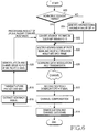
- FIG. 6 is a flow diagram illustrating operations of the transmitter and the receiver according to the first embodiment of the present invention. Hereinafter, the operations of the transmitter and the receiver according to the first embodiment of the present invention will be described in detail with reference to FIG. 6.
- step 600 the transmitter determines whether a current timing is an acknowledgement timing for packet data. Specifically, in step 600, whether received packet data contain an error and the data are retransmitted are determined. As a result of the determination, when the current timing is the acknowledgement timing, step 602 is performed. In contrast, when the current timing is not the acknowledgement timing, step 604 is performed.
- that the current timing is not the acknowledgement timing may represent a case in which a node B have not received the uplink packet data transmitted from a UE.
- step 602 the transmitter converts a processing result of the uplink packet channel into a binary ACK/NACK signal.
- the ACK/NACK signal has a value of +1 or -1.
- the value +1 implies that an error has occurred in the received packet data and the value -1 implies that an error has not occurred in the received packet data.
- an ACK/NACK signal having a value of +1 as a basic value is generated.
- the transmitter multiplies the ACK/NACK signal by a pilot signal and inserts the multiplication result into a DPCH frame.
- step 608 the transmitter modulates the DPCH frame and transmits the modulated DPCH frame to the receiver.
- a progress to step 610 from step 608 corresponds to transmission on a radio channel.
- step 610 the receiver receives the DPCH signal transmitted from the transmitter and despreads the received DPCH signal. Then, step 612 is performed. That is, the receiver performs a channel compensation process. In step 614, the receiver performs a demodulation and a channel decoding for the received signal that experienced the channel compensation process. Meanwhile, in step 616, the receiver extracts the ACK/NACK signal from the received signal that experienced the channel compensation process. A process of extracting the ACK/NACK signal is as described in FIG. 5.
- step 618 the receiver determines whether the uplink packet data are retransmitted on the basis of the ACK/NACK signal. That is, in the case of the NACK, the previously transmitted packet data are retransmitted. In contrast, in the case of the ACK, new packet data are retransmitted.
- step 620 the transmitter performs a demodulation and a decoding for the uplink packet data, determines whether an error has occurred in the uplink packet data, and sends a processing result for the uplink packet channel to step 602.
- a pilot field transmitted through a DPCCH is used as a phase reference in a channel estimation process performed for generating an exact beam according to each UE.
- the phase of a dedicated pilot is inverted according to an ACK or an NACK and a pilot pattern different from the pilot pattern already known to a node B and a UE is transmitted. Therefore, there may occur a case in which a channel estimation cannot be performed.
- a second embodiment which will be described hereinafter proposes a scheme of inserting ACK/NACK information into a pilot signal and transmitting the pilot signal without influencing a channel estimation using the dedicated pilot.
- the second embodiment proposes a scheme of inserting ACK/NACK information into a pilot field without influencing a channel estimation using the dedicated pilot signal.
- the pilot field of a DPCH instead of a CPICH is used as a phase reference for a channel estimation.
- FIG. 7 is a block diagram showing the structure of a transmitter for transmitting ACK/NACK information according to the second embodiment of the present invention.
- the second embodiment proposes a scheme for transmitting the ACK/NACK information by means of the pilot field of the conventional downlink DPCH.
- the transmitter includes a DPDCH generator 700, a DPCCH generator 702, a mutiplexer 704, a pilot pattern inserting unit 706, a modulator 708 and a pilot pattern selector 710.
- a node B having received uplink packet data from a UE demodulates the received data.
- the node B analyzes whether the received data contain an error and generates ACK/NACK information.
- the node B When the received data contain an error, the node B generates NACK information requesting retransmission of the packet data.
- the node B when the received data does not contain an error, the node B generates ACK information which does not request the retransmission of the packet data.
- the generated ACK/NACK information is transmitted to the pilot pattern selector 710.
- the pilot pattern selector 710 generates a specific ACK/NACK signal according to the received ACK/NACK information. That is, when the received ACK/NACK information is ACK information, the pilot pattern selector 710 generates a preset p i1 (n). In contrast, when the received information is NACK information, the pilot pattern selector 710 generates a preset p i0 (n).
- the p i0 (n) is the same as a pilot pattern for the conventional i th slot and the p i1 (n) is a new pilot pattern defined to be perpendicular to the p i0 (n).
- the ACK/NACK pilot signal which is an output of the pilot pattern selector 710, is transmitted to the pilot pattern inserting unit 706.
- the DPDCH generator 700 generates DPDCH data by means of a received DCH and transmits the generated DPDCH data to the mutiplexer 704.
- the DPCCH generator 702 generates DPCCH data by means of a received TPC information and TFCI, and transmits the generated DPCCH data to the mutiplexer 704.
- the mutiplexer 704 transmits DPCH data obtained by multiplexing the received DPDCH data and DPCCH data to the pilot pattern inserting unit 706.
- the pilot pattern inserting unit 706 outputs a DPCH frame obtained by time-multiplexing the ACK/NACK pilot signal transmitted from the pilot pattern selector 710 with the DPCH data.
- the time-multiplexed DPCH frame is modulated by the modulator 708 and is then sent through a transmission antenna.
- FIG. 8 is a block diagram showing the structure of a receiver according to the second embodiment of the present invention.
- ACK/NACK information is restored in a step before a channel compensation.
- the reception signal transmitted from the transmitter is demodulated and is then sent to a channel estimator 804 and a channel compensator 800.
- the channel estimator 804 performs a channel estimation process by means of the reception signal and simultaneously extracts a pilot signal used as the ACK/NACK information from the reception signal.
- the channel estimator 804 will be described in detail with reference to FIG. 9 later.
- a channel estimated value generated by the channel estimator 804 is sent to the channel compensator 800 and the extracted ACK/NACK information is sent to a packet channel adjuster 806.
- the received signal that experienced a channel compensation process in the channel compensator 800 is transmitted to a modulator 802.
- the modulator 802 modulates the received signal to output DPCH data.
- the packet channel adjuster 806 determines whether uplink packet data are retransmitted according to the received ACK/NACK information.
- the pilot signal is extracted before the channel estimation.
- a pilot pattern may be extracted from a data symbol for which a channel compensation has been completed and the extracted pilot pattern used. That is, in this embodiment of the present invention, the pilot signal used as ACK/NACK information may be extracted at any positions regardless of the positions of the channel estimator 804. Those who are skilled in the art can easily construct the receiver regardless of extracted positions of the pilot signal.
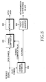
- FIG. 9 is a block diagram showing the structure of the channel estimator 804 according to the second embodiment of the present invention.
- the channel estimator 804 includes a DPCH reception judgment unit 900, a DPCH pilot extractor 902, multipliers 904 and 906, accumulators 908 and 910, a comparator 912 and an ACK/NACK judgment unit 914.
- a DPCH reception judgment unit 900 a DPCH pilot extractor 902
- multipliers 904 and 906 accumulators 908 and 910
- comparator 912 ACK/NACK judgment unit 914
- the DPCH reception judgment unit 900 determines whether a channel to be currently received is a DPCH.
- a current time time slot
- ACK/NACK information a processing result for a channel decoding of an uplink packet channel
- the DPCH pilot extractor 902 extracts only a pilot field component of the DPCH signal from the reception signal and outputs the extracted pilot field component to the multipliers 904 and 906.
- the multipliers 904 and 906 receive the pilot symbols of the pilot field component.
- the following equation 4 represents the signals input to the multipliers 904 and 906.
- the multiplier 904 performs a multiplication for the input pilot symbols and a p * / i 0( n ) which is a pilot pattern assigned to an i th slot and sends the multiplication result to the accumulator 908.
- the multiplier 906 performs a multiplication for the input pilot symbols and a p * / i 1 ( n ) which is perpendicular to the p * / i 0 (n ) and is a pilot pattern assigned to ACK information, and sends the multiplication result to the accumulator 912.
- the accumulators 908 and 910 accumulate the signals sent from each of the multipliers 904 and 906 by a predetermined period of time.
- the following equation 5 represents a signal outputted from an k th accumulator according to operations performed by the accumulators 908 and 910.
- the comparator 912 compares the sizes of the signals transmitted from the accumulators 908 and 910. As a result of the comparison, when the signal transmitted from the accumulator 908 has a size larger than that transmitted from the accumulator 910, the comparator 912 outputs the output of the accumulator 908 as a channel estimation value. In contrast, when the signal transmitted from the accumulator 910 has a size larger than that transmitted from the accumulator 908, the comparator 912 outputs the output of the accumulator 910 as a channel estimation value. The comparator 912 sends the output of the accumulator 908 or the accumulator 910 to the channel compensator 800 according to the comparison result.
- the ACK/NACK judgment unit 914 determines an ACK/NACK according to the comparison result and sends the result of the determination to the packet channel adjuster 806. In detail, when the signal transmitted from the accumulator 908 has a size larger than that transmitted from the accumulator 910, the ACK/NACK judgment unit 914 determines the received signal to be an ACK. In contrast, when the signal transmitted from the accumulator 910 has a size larger than that transmitted from the accumulator 908, the ACK/NACK judgment unit 914 determines the received signal to be an NACK.
- the detection of an ACK/NACK based on a selected accumulator is performed according to the type of pilot patterns used in the multipliers 904 and 906. That is, when the value of a accumulator accumulating the value of a multiplier multiplying a preset pilot pattern of a corresponding slot is selected, the ACK/NACK judgment unit 914 determines the received signal to be an ACK. In contrast, when the value of a accumulator accumulating the value of a multiplier multiplying a pilot pattern of an ACK information is selected, the ACK/NACK judgment unit 914 determines the received signal to be an NACK.
- FIG. 10 is a flow diagram illustrating operations of the transmitter and the receiver according to the second embodiment of the present invention. Hereinafter, the operations of the transmitter and the receiver according to the second embodiment of the present invention will be described in detail with reference to FIG. 10.
- step 1000 the transmitter determines whether a current timing is an acknowledgement timing for packet data. Specifically, in step 1000, whether received packet data contain an error and data are retransmitted are determined. As a result of the determination, when the current timing is the acknowledgement timing, step 1002 is performed. In contrast, when the current timing is not the acknowledgement timing, step 1004 is performed. In step 1002, the transmitter selects a pilot pattern corresponding to a processing result of an uplink packet channel.
- the pilot pattern corresponding to the processing result of the uplink packet channel includes a p i0 (n) or a p i1 (n).
- the p i0 (n) is a preset pilot pattern of a corresponding i th slot and indicates that there is no error in the received packet data (i.e. ACK).
- the p i1 (n) is a pattern perpendicular to the preset pilot pattern and indicates that an error has occurred in the received packet data (i.e. NACK).
- the p i0 (n) is selected as a pilot pattern.
- step 1006 The pilot pattern selected in step 1002 or step 1004 is sent to step 1006.
- step 1006 the transmitter inserts a pilot signal having the selected pilot pattern into a DPCH frame.
- step 1008 the transmitter modulates the DPCH frame and transmits the modulated DPCH frame to the receiver.
- a progress to step 1010 from step 1008 corresponds to transmission on a radio channel.
- step 1010 the receiver receives the DPCH signal transmitted from the transmitter and despreads the received DPCH signal. Then, step 1012 is performed. That is, the receiver performs a channel estimation process. In steps 1014 and 1016, the receiver performs a channel compensation, a demodulation and a channel decoding for the received DPCH signal. Meanwhile, in step 1018, the receiver extracts a pilot pattern of a pilot signal corresponding to ACK/NACK information from the received signal that experienced the channel estimation. A process of extracting the ACK/NACK signal is as described in FIG. 9.
- step 1020 the receiver determines whether the uplink packet data are retransmitted on the basis of the ACK/NACK signal. That is, in the case of the NACK, the previously transmitted packet data are retransmitted. In contrast, in the case of the ACK, new packet data are retransmitted.
- step 1022 the transmitter performs a demodulation and a decoding for the received uplink packet data, determines whether there is an error in the uplink packet data through the demodulation and the decoding, and sends a processing result for the uplink packet channel to step 1002.
- the first embodiment and the second embodiment relate to methods for transmitting two types of control information, that is, ACK information and NACK information.
- the third embodiment relates to a method for transmitting two or more types of control information, that is, plural control information within a generation range of an orthogonal pattern set.
- control information is MISS/ACK/NACK information.
- the third embodiment provides a scheme of inserting MISS/ACK/NACK information into a pilot field without influencing channel estimation using a dedicated pilot.
- the MISS as the control information represents an occurrence of a case in which packet data has been transmitted at a predetermined transmission time but a reception side does not recognize the reception of the packet data. In such a case, the reception side transmits MISS information by means of a conventional pilot pattern or a predetermined pilot pattern instead of ACK information or NACK information.
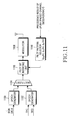
- FIG. 11 is a block diagram illustrating the structure of a transmitter for transmitting control information according to the third embodiment of the present invention.
- the third embodiment provides a scheme for transmitting the MIS/ACK/NACK information by means of the pilot field of the conventional downlink DPCH.
- the transmitter includes a DPDCH generator 1100, a DPCCH generator 1102, a mutiplexer 1104, a pilot bit inserting unit 1106, a modulator 1108 and a pilot pattern selector 1110.
- a node B having received uplink packet data from a UE demodulates the received data.
- the node B analyzes whether the received data contain an error and generates control information.
- the node B When the received data contain an error, the node B generates NACK information requesting retransmission of the packet data.
- the node B when the received data do not contain an error, the node B generates ACK information representing the normal reception of the corresponding data.
- the node B when it is determined that the packet data are not received at a desired time point, the node B generates MISS information representing that the corresponding data have not been received.
- the generated control information is transmitted to the pilot pattern selector 1110.
- the pilot pattern selector 1110 generates a specific pilot signal according to the received control information. For example, when the control information is the MISS information, the pilot pattern selector 1110 generates a preset p i0 (n). When the control information is ACK information, the pilot pattern selector 1110 generates a preset p i1 (n). Further, when the control information is NACK information, the pilot pattern selector 1110 generates a preset p i,2 (n). The p i0 (n) has the same pilot pattern as that for an existing i th slot.
- the p i1 (n) and the p i,2 (n) are perpendicular to the p i0 (n) and represents a new pilot pattern defined so that the p i1 (n) and the p i,2 (n) are perpendicular to each other. It is possible to define the p i1 (n) and the p i,2 (n) having an orthogonality for every p i0 (n) in relation to an N pilot larger than or equal to 2.
- the MISS/ACK/NACK pilot signal which is an output of the pilot pattern selector 1110, is transmitted to the pilot bit inserting unit 1106.
- the DPDCH generator 1100 generates DPDCH data by means of received DCH data and transmits the generated DPDCH data to the mutiplexer 1104.
- the DPCCH generator 1102 generates DPCCH data by means of a received TPC bit and TFCI bit, and transmits the generated DPCCH data to the mutiplexer 1104.
- the mutiplexer 1104 transmits DPCH data obtained by multiplexing the received DPDCH data and DPCCH data to the pilot bit inserting unit 1106.
- the pilot bit inserting unit 1106 generates a DPCH frame by time-multiplexing the MISS/ACK/NACK pilot signal transmitted from the pilot pattern selector 1110 with the DPCH data.
- the time-multiplexed DPCH frame is modulated by the modulator 1108 and is then transmitted through a transmission antenna.
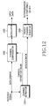
- FIG. 12 is a block diagram illustrating the structure of a receiver according to the third embodiment of the present invention.
- the MISS/ACK/NACK information is extracted prior to channel compensation.
- the reception signal transmitted from the transmitter is demodulated and is then transferred to a channel estimator 1204 and a channel compensator 1200.
- the channel estimator 1204 performs a channel estimation process by means of the reception signal and simultaneously extracts a pilot signal used as the MISS/ACK/NACK information from the reception signal.
- the channel estimator 1204 will be described in detail with reference to FIG. 13.
- a channel estimated value generated by the channel estimator 1204 is transferred to the channel compensator 1200 and the extracted MISS/ACK/NACK information is transferred to a packet channel adjuster 1206.
- the channel compensator 1200 performs a channel compensation process by means of the channel estimated value generated by the channel estimator 1204.
- the reception signal that experienced the channel compensation process in the channel compensator 1200 is transmitted to a modulator 1202.
- the modulator 1202 modulates the reception signal to output DPCH data.
- the packet channel adjuster 1206 determines whether uplink packet data are retransmitted according to the received MISS/ACK/NACK information.
- the pilot signal is extracted before channel estimation occurs.
- a pilot pattern may be extracted from a data symbol for which a channel compensation has been completed and the extracted pilot pattern used. That is, in this embodiment of the present invention, the pilot signal used as MISS/ACK/NACK information may be extracted at any position regardless of the position of the channel estimator 1204. Those who are skilled in the art can easily construct the receiver regardless of extracted positions of the pilot signal.
- FIG. 13 is a block diagram illustrating the structure of the channel estimator 1204 according to the third embodiment of the present invention.
- the channel estimator 1204 includes a DPCH reception judgment unit 1300, a DPCH pilot extractor 1302, multipliers 1304, 1306 and 1308, accumulators 1310, 1312 and 1314, a comparator 1316 and a MISS/ACK/NACK judgment unit 1318.
- a DPCH reception judgment unit 1300 a DPCH pilot extractor 1302, multipliers 1304, 1306 and 1308, accumulators 1310, 1312 and 1314, a comparator 1316 and a MISS/ACK/NACK judgment unit 1318.
- FIG. 13 the structure of the channel estimator 1204 will be described in detail with reference to FIG. 13.
- the DPCH reception judgment unit 1300 determines whether a channel to be currently received is a DPCH.
- a current time time slot
- a processing result such as MISS/ACK/NACK information
- the DPCH pilot extractor 1302 extracts only a pilot field component of the DPCH signal from the reception signal and outputs the extracted pilot field component to the multipliers 1304, 1306 and 1308.
- the multipliers 1304, 1306 and 1308 receive the pilot symbols of the pilot field component.
- the following equation 6 represents the pilot signals input to the multipliers 1304, 1306 and 1308.
- the multiplier 1304 performs a multiplication for the input pilot symbols and a p * / i 0( n ) which is a pilot pattern assigned to an i th slot and transfers the multiplication result to the accumulator 1310.
- the multiplier 1306 performs multiplication for the input pilot symbols and a p * / i 1 (n) which is perpendicular to the p * / i 0( n ) and is a pilot pattern assigned to ACK information, and transfers the multiplication result to the accumulator 1312.
- the multiplier 1308 performs multiplication for the input pilot symbols and a p * / i 2( n ) which is perpendicular to the p * / i 0( n ) and the p * / i 1( n ) and is a pilot pattern assigned to MISS information, and transfers the multiplication result to the accumulator 1314.
- the accumulators 1310, 1312 and 1314 accumulate the signals received from each of the multipliers 1304, 1306 and 1308 by a predetermined period of time.
- the following equation 7 represents a signal output from a k th accumulator of the accumulators 1310, 1312 and 1314.
- the k represents an index designating a specific accumulator.
- an index designating the accumulator 1310 is 0, an index designating the accumulator 1312 is 1, and an index designating the accumulator 1314 is 2.
- the comparator 1316 compares the sizes of the signals transmitted from the accumulators 1310, 1312 and 1314.
- the comparison of the size may be replaced with a comparison of absolute values of the signals.
- the comparator 1316 selects and outputs the largest one of the signals from the accumulators 1310, 1312 and 1314.
- a k value corresponding to the selected signal or control information corresponding to the k value is output.
- the control information may be determined by the k value.
- the comparator 1316 outputs the output value of the accumulator 1310 as a channel estimation value.
- a value 0 is output as a k value designating the accumulator 1310.
- the comparator 1316 outputs the output value of the accumulator 1312 as a channel estimation value.
- a value 1 is output as a k value designating the accumulator 1312.
- the comparator 1316 when the signal transferred from the accumulator 1314 is larger than the signals transferred from the accumulators 1310 and 1312, the comparator 1316 outputs the output value of the accumulator 1314 as a channel estimation value.
- a value 2 is output as a k value designating the accumulator 1314.
- the MISS/ACK/NACK judgment unit 1318 determines control information. That is, the MISS/ACK/NACK detection unit 1318 determines whether the k value output from the comparator 1316 is MISS information, ACK information or NACK information and notifies the packet channel adjuster 1206 of the determination. For example, when the k value is 0, the MISS/ACK/NACK judgment unit 1318 determines that the control information is the MISS information. When the k value is 1, the MISS/ACK/NACK detection unit 1318 determines that the control information is the ACK information. Further, when the k value is 2, the MISS/ACK/NACK judgment unit 1318 determines that the control information is the NACK information. This determination is performed according to the pilot patterns used in the multipliers 1304, 1306 and 1308 and a predetermined reference for determining the control information by the k values.
- FIG. 14 is a flow diagram illustrating operations of the transmitter and the receiver according to the third embodiment of the present invention.
- the operations of the transmitter and the receiver according to the third embodiment of the present invention will be described in detail with reference to FIG. 14.
- step 1400 the transmitter determines whether a current timing is an acknowledgement timing for packet data. Further, in step 1400, the transmitter determines whether received packet data contain an error and data are retransmitted. As a result of the determination, when the current timing is the acknowledgement timing, step 1402 is performed. In contrast, when the current timing is not the acknowledgement timing, step 1404 is performed.
- the transmitter selects a pilot pattern corresponding to a processing result of an uplink packet channel.
- the pilot pattern corresponding to the processing result of the uplink packet channel includes a p i0 (n), a p i1 (n) or a p i2 (n).
- the p i0 (n) is a preset pilot pattern of a corresponding i th slot and indicates that corresponding packet data have not been received, that is MISS.
- the p i1 (n) is a pattern perpendicular to the preset pilot pattern and indicates that the received packet data do not contain an error, that is, ACK.
- the p i2 (n) is a pattern perpendicular to the preset pilot pattern and indicates that the received packet data contain an error, that is, NACK.
- the conventional pilot pattern p i0 (n) is selected.
- step 1406 is performed.
- the transmitter inserts a pilot signal having the selected pilot pattern into a DPCH frame through time multiplexing.
- step 1408 the transmitter modulates the DPCH frame and transmits the modulated DPCH frame to the receiver. Specifically, progress to step 1010 from step 1008 corresponds to transmission on a radio channel.
- step 1410 the receiver receives the DPCH signal transmitted from the transmitter and despreads the received DPCH signal. Then, step 1412 is performed to allow the receiver to perform a channel estimation process.
- steps 1414 and 1416 the receiver performs channel compensation, and a demodulation and a channel decoding for the received DPCH signal.
- step 1418 the receiver extracts a pilot pattern of a pilot signal corresponding to MISS/ACK/NACK information from the received signal that experienced the channel estimation, thereby obtaining the control information from the transmitter.
- a process of obtaining the control information by extracting the pilot pattern is as described in FIG. 13. That is, the receiver obtains the control information from the transmitter by comparing the sizes of correlation values of the signals that experienced the channel estimation process.
- the receiver determines that the transmitter has not received the desired packet data.
- the receiver determines that the transmitter has normally received the desired packet data.
- the receiver determines that the desired packet data received in the transmitter contain an error. Then, in step 1420, the receiver retransmits the previously transmitted packet data or transmits the next packet data.
- the transmitter performs a demodulation and a decoding for the received uplink packet data, determines whether there is an error in the uplink packet data through the demodulation and the decoding, and outputs control information corresponding to a processing result for the uplink packet channel.
- the control information is MISS information, ACK information or NACK information.
- the transmitter performs aforementioned steps 1402, 1404, 1406 and 1408 by the control information.
- the this embodiment of the present invention discloses a method by which a Node B transmits a processing result for an uplink packet channel by means of a DPCH pilot field of a downlink, and a UE extracts the DPCH pilot field, determines the processing result for the uplink packet channel, and operates an automatic retransmission request (ARQ) or a hybrid automatic retransmission request (HARQ) of the uplink packet channel.
- ARQ automatic retransmission request
- HARQ hybrid automatic retransmission request
- a separate physical channel is not used in order to transmit a channel decoding result (control information) of the uplink packet channel, so that additional power and an orthogonal variable spreading factors (OVSF) code are not consumed.
- OVSF orthogonal variable spreading factors
- the processing result (control information) for the uplink packet channel is transmitted without the loss of data of an existing physical channel, so that the performance of the physical channel is prevented from deteriorating.
- the processing result (control information) for the uplink packet channel is transmitted without the loss of data of an existing physical channel, so that the performance of the physical channel is prevented from deteriorating.
- the amount of information to be transmitted through the downlink can be reduced.
Landscapes
- Engineering & Computer Science (AREA)
- Computer Networks & Wireless Communication (AREA)
- Signal Processing (AREA)
- Power Engineering (AREA)
- Mobile Radio Communication Systems (AREA)
- Detection And Prevention Of Errors In Transmission (AREA)
Applications Claiming Priority (2)
| Application Number | Priority Date | Filing Date | Title |
|---|---|---|---|
| KR2004009401 | 2004-02-12 | ||
| KR20040009401A KR100703382B1 (ko) | 2003-11-15 | 2004-02-12 | 이동통신 시스템에서 제어 정보 전송 장치 및 방법 |
Publications (1)
| Publication Number | Publication Date |
|---|---|
| EP1564923A1 true EP1564923A1 (de) | 2005-08-17 |
Family
ID=34698982
Family Applications (1)
| Application Number | Title | Priority Date | Filing Date |
|---|---|---|---|
| EP20050002948 Withdrawn EP1564923A1 (de) | 2004-02-12 | 2005-02-11 | Vorrichtung und Verfahren zur Kontrollinformationsübertragung in einem Mobilkommunikationssystem |
Country Status (3)
| Country | Link |
|---|---|
| EP (1) | EP1564923A1 (de) |
| JP (1) | JP2005244967A (de) |
| CN (1) | CN1697363A (de) |
Cited By (5)
| Publication number | Priority date | Publication date | Assignee | Title |
|---|---|---|---|---|
| WO2008084377A3 (en) * | 2007-01-08 | 2008-12-04 | Nokia Corp | Method and apparatus for providing control signaling |
| US7733917B2 (en) * | 2004-02-14 | 2010-06-08 | Samsung Electronics Co., Ltd. | Apparatus and method for transmitting control information in a mobile communication system |
| EP2187546A4 (de) * | 2007-08-31 | 2012-12-12 | Fujitsu Ltd | Steuerinformations-kommunikationsverfahren und einrichtung dafür |
| EP2840750A1 (de) * | 2013-08-22 | 2015-02-25 | Alcatel Lucent | Nichtdeterministisches Pilotensymbolschema |
| US9392470B2 (en) | 2007-08-13 | 2016-07-12 | Godo Kaisha Ip Bridge 1 | Integrated circuit for radio transmission of ACK/NACK signal |
Families Citing this family (5)
| Publication number | Priority date | Publication date | Assignee | Title |
|---|---|---|---|---|
| WO2007078146A1 (en) | 2006-01-06 | 2007-07-12 | Samsung Electronics Co., Ltd. | Method and apparatus for transmitting/receiving uplink signaling information in a single carrier fdma system |
| KR100881967B1 (ko) | 2006-01-06 | 2009-02-04 | 삼성전자주식회사 | 단반송파 주파수 분할 다중접속 시스템에서 역방향 정보들의 송수신 방법 및 장치 |
| WO2008060203A1 (en) * | 2006-11-13 | 2008-05-22 | Telefonaktiebolaget Lm Ericsson (Publ) | Method and arrangement for pilot pattern based control signalling in mimo systems |
| CN201319670Y (zh) * | 2007-02-05 | 2009-09-30 | 美商内数位科技公司 | 用于寻呼的无线发射/接收单元和基站 |
| JP5338893B2 (ja) * | 2011-12-19 | 2013-11-13 | 富士通株式会社 | 制御情報通信方法及びその装置 |
Citations (4)
| Publication number | Priority date | Publication date | Assignee | Title |
|---|---|---|---|---|
| EP0991204A2 (de) * | 1998-09-29 | 2000-04-05 | Nec Corporation | Verfahren zur Sendeleistungsregelung mit Pilotensymbolsmuster |
| US6285663B1 (en) * | 1998-06-05 | 2001-09-04 | Telefonaktiebolaget Lm Ericsson (Publ) | Increasing performance in communications by embedding one signal in another signal |
| US20020002050A1 (en) * | 1998-12-22 | 2002-01-03 | Mikko Rinne | Signalling method and telecommunication system |
| EP1349292A2 (de) * | 2002-03-26 | 2003-10-01 | Samsung Electronics Co., Ltd. | Verfahren und Vorrichtung zur Kodierung und Dekodierung von Kanalqualitätsindikator Information in einem Kommunikationssystem mit Hochgeschwindigkeits-Abwärtsrichtung-Paket-Zugriff |
-
2005
- 2005-02-11 EP EP20050002948 patent/EP1564923A1/de not_active Withdrawn
- 2005-02-14 JP JP2005036929A patent/JP2005244967A/ja active Pending
- 2005-02-16 CN CNA2005100716756A patent/CN1697363A/zh active Pending
Patent Citations (4)
| Publication number | Priority date | Publication date | Assignee | Title |
|---|---|---|---|---|
| US6285663B1 (en) * | 1998-06-05 | 2001-09-04 | Telefonaktiebolaget Lm Ericsson (Publ) | Increasing performance in communications by embedding one signal in another signal |
| EP0991204A2 (de) * | 1998-09-29 | 2000-04-05 | Nec Corporation | Verfahren zur Sendeleistungsregelung mit Pilotensymbolsmuster |
| US20020002050A1 (en) * | 1998-12-22 | 2002-01-03 | Mikko Rinne | Signalling method and telecommunication system |
| EP1349292A2 (de) * | 2002-03-26 | 2003-10-01 | Samsung Electronics Co., Ltd. | Verfahren und Vorrichtung zur Kodierung und Dekodierung von Kanalqualitätsindikator Information in einem Kommunikationssystem mit Hochgeschwindigkeits-Abwärtsrichtung-Paket-Zugriff |
Cited By (12)
| Publication number | Priority date | Publication date | Assignee | Title |
|---|---|---|---|---|
| US7733917B2 (en) * | 2004-02-14 | 2010-06-08 | Samsung Electronics Co., Ltd. | Apparatus and method for transmitting control information in a mobile communication system |
| WO2008084377A3 (en) * | 2007-01-08 | 2008-12-04 | Nokia Corp | Method and apparatus for providing control signaling |
| US7957317B2 (en) | 2007-01-08 | 2011-06-07 | Nokia Corporation | Method and apparatus for providing control signaling |
| EP2645617A1 (de) * | 2007-01-08 | 2013-10-02 | Nokia Corporation | Verfahren und Vorrichtung zum Bereitstellen von Steuersignalisierung |
| US9392470B2 (en) | 2007-08-13 | 2016-07-12 | Godo Kaisha Ip Bridge 1 | Integrated circuit for radio transmission of ACK/NACK signal |
| US9584289B2 (en) | 2007-08-13 | 2017-02-28 | Godo Kaisha Ip Bridge 1 | Radio transmission device and radio transmission method |
| US10158475B2 (en) | 2007-08-13 | 2018-12-18 | Godo Kaisha Ip Bridge 1 | Radio transmission device and radio transmission method |
| US10826669B2 (en) | 2007-08-13 | 2020-11-03 | Godo Kaisha Ip Bridge 1 | Radio transmission device and radio transmission method |
| US11444739B2 (en) | 2007-08-13 | 2022-09-13 | Godo Kaisha Ip Bridge 1 | Radio transmission device and radio transmission method |
| EP2187546A4 (de) * | 2007-08-31 | 2012-12-12 | Fujitsu Ltd | Steuerinformations-kommunikationsverfahren und einrichtung dafür |
| EP2840750A1 (de) * | 2013-08-22 | 2015-02-25 | Alcatel Lucent | Nichtdeterministisches Pilotensymbolschema |
| WO2015024856A1 (en) * | 2013-08-22 | 2015-02-26 | Alcatel Lucent | Non-deterministic pilot symbol scheme |
Also Published As
| Publication number | Publication date |
|---|---|
| JP2005244967A (ja) | 2005-09-08 |
| CN1697363A (zh) | 2005-11-16 |
Similar Documents
| Publication | Publication Date | Title |
|---|---|---|
| US7733917B2 (en) | Apparatus and method for transmitting control information in a mobile communication system | |
| EP1531576A2 (de) | Gerät und Verfahren zum Senden von Steuerungsinformation in einem Mobilkommunikationssystem | |
| CA2438364C (en) | Mobile communication system, base station, and communication control method | |
| KR101513503B1 (ko) | Dual-cell HSDPA 를 지원하는 이동통신 시스템에서 CQI전송 오버헤드를 감소시키는 방법 및 장치 | |
| EP2635071B1 (de) | Signalisierung für Enhanced Uplink Dedicated Transport Channel | |
| EP1313232B1 (de) | Verfahren und Vorrichtung für die Leistungsregelung des Aufwärtskanals in einem CDMA Kommunikationssystem | |
| US8208447B2 (en) | Pilot signal enhancements for a wireless communication system | |
| EP1523109A2 (de) | Unterstützung von Abwärtsstreckenmehrbenutzerdetektion | |
| US8094701B2 (en) | Channel estimation for high data rate transmission using multiple control channels | |
| EP1681780A1 (de) | System und Vorrichtung für Funkkommunikation | |
| US8009616B2 (en) | Radio access method, radio base station and radio terminal | |
| CA2312772A1 (en) | Method and apparatus for coherently-averaged power estimation | |
| JP4557982B2 (ja) | 代替スクランブルコードを用いた、cdmaシステムにおける干渉推定 | |
| US20040101071A1 (en) | Radio base station apparatus, decoding apparatus used therefor which uses TFCI decoding characteristics, and decoding method therefor | |
| US7903595B2 (en) | Apparatus and method for transmitting and receiving a reverse channel in a mobile communication system for packet data | |
| US20050201486A1 (en) | Apparatus and method for transmitting control information in a mobile communication system | |
| EP1564923A1 (de) | Vorrichtung und Verfahren zur Kontrollinformationsübertragung in einem Mobilkommunikationssystem | |
| US20030220122A1 (en) | Apparatus and method for receiving channel signal using space time transmit diversity scheme in code division multiple access communication system | |
| KR20080019291A (ko) | 공유 제어 채널 검출 전략 | |
| KR100354471B1 (ko) | 부가 정보 비트가 삽입된 파일럿 신호에서 파일럿 비트를복구하는 무선 이동 통신 시스템 | |
| JP2005051713A (ja) | パケット伝送方法および通信装置 | |
| US20060193253A1 (en) | Radio base station | |
| JP2001339325A (ja) | 無線受信装置 |
Legal Events
| Date | Code | Title | Description |
|---|---|---|---|
| PUAI | Public reference made under article 153(3) epc to a published international application that has entered the european phase |
Free format text: ORIGINAL CODE: 0009012 |
|
| 17P | Request for examination filed |
Effective date: 20050211 |
|
| AK | Designated contracting states |
Kind code of ref document: A1 Designated state(s): AT BE BG CH CY CZ DE DK EE ES FI FR GB GR HU IE IS IT LI LT LU MC NL PL PT RO SE SI SK TR |
|
| AX | Request for extension of the european patent |
Extension state: AL BA HR LV MK YU |
|
| AKX | Designation fees paid |
Designated state(s): DE FR GB IT |
|
| STAA | Information on the status of an ep patent application or granted ep patent |
Free format text: STATUS: THE APPLICATION HAS BEEN WITHDRAWN |
|
| 18W | Application withdrawn |
Effective date: 20090319 |