EP1565234B1 - Defibrillator mit einer relais-testeinrichtung - Google Patents
Defibrillator mit einer relais-testeinrichtung Download PDFInfo
- Publication number
- EP1565234B1 EP1565234B1 EP03767564A EP03767564A EP1565234B1 EP 1565234 B1 EP1565234 B1 EP 1565234B1 EP 03767564 A EP03767564 A EP 03767564A EP 03767564 A EP03767564 A EP 03767564A EP 1565234 B1 EP1565234 B1 EP 1565234B1
- Authority
- EP
- European Patent Office
- Prior art keywords
- relay
- defibrillator
- voltage
- discharge resistor
- testing
- Prior art date
- Legal status (The legal status is an assumption and is not a legal conclusion. Google has not performed a legal analysis and makes no representation as to the accuracy of the status listed.)
- Expired - Lifetime
Links
Images
Classifications
-
- A—HUMAN NECESSITIES
- A61—MEDICAL OR VETERINARY SCIENCE; HYGIENE
- A61N—ELECTROTHERAPY; MAGNETOTHERAPY; RADIATION THERAPY; ULTRASOUND THERAPY
- A61N1/00—Electrotherapy; Circuits therefor
- A61N1/18—Applying electric currents by contact electrodes
- A61N1/32—Applying electric currents by contact electrodes alternating or intermittent currents
- A61N1/38—Applying electric currents by contact electrodes alternating or intermittent currents for producing shock effects
- A61N1/39—Heart defibrillators
- A61N1/3925—Monitoring; Protecting
- A61N1/3931—Protecting, e.g. back-up systems
-
- A—HUMAN NECESSITIES
- A61—MEDICAL OR VETERINARY SCIENCE; HYGIENE
- A61N—ELECTROTHERAPY; MAGNETOTHERAPY; RADIATION THERAPY; ULTRASOUND THERAPY
- A61N1/00—Electrotherapy; Circuits therefor
- A61N1/18—Applying electric currents by contact electrodes
- A61N1/32—Applying electric currents by contact electrodes alternating or intermittent currents
- A61N1/38—Applying electric currents by contact electrodes alternating or intermittent currents for producing shock effects
- A61N1/39—Heart defibrillators
- A61N1/3906—Heart defibrillators characterised by the form of the shockwave
- A61N1/3912—Output circuitry therefor, e.g. switches
Definitions
- the invention relates to a defibrillator with a power amplifier, which has a high voltage part and with this by means of a coupling circuit automatically connectable via a relay patient electrode terminals and a relay test device, in particular a portable external defibrillator.
- Such a defibrillator is disclosed in EP 0 946 956 B1.
- a method is provided with which a relay is tested, which is arranged in a coupling circuit between a high voltage part and patient electrodes and on the one hand in an open position and on the other hand in a closed position in which the patient electrodes are connected to the high voltage part, can be brought.
- a test procedure is carried out in which a discharge of an energy store in the form of a capacitor storing the energy for the defibrillation pulse is carried out via the relay and the patient electrodes and the voltage across the capacitor is measured.
- the voltage of the capacitor during discharge is compared with a threshold voltage to return to the relay state. It is difficult to derive a reliable statement about the relay state in this way in different situations.
- a particular portable automatic external defibrillator with a specially designed high-voltage part with H-bridge and in the transverse branch in series with an inductance (coil or equivalent component) connected patient electrodes is given in DE 100 65 104 A1.
- advantageous biphasic defibrillation pulses can be generated by appropriate control of switching elements of the H-bridge.
- a relay test is not specified.
- US 5,879,374 discloses a defibrillator according to the preamble of claim 1. In this defibrillator there is a relay test device which, however, does not involve the state of the discharge resistor arrangement.
- the invention has for its object to provide a particularly portable external defibrillator of the type mentioned, with the test of the coupling relay is possible to carry out as reliably as possible.
- the connected discharge resistor arrangement provides reliable conditions for testing the relay so that a reliable evaluation of the relay state is achieved.
- Reliable testing of the coupling relay is facilitated by the fact that the relay test device has its own power supply for a test supply voltage with which a current through the relay can be effected for testing the relay when the discharge resistor arrangement is connected Power is suppressed by the high voltage part.
- a further advantageous embodiment of the relay test device is that it has a measuring branch, in the applied voltage discharge arrangement on the one hand and in non-adjacent discharge resistor on the other hand, different voltages or measuring currents applied, which are included in the testing of the relay.
- the measuring branch having a measuring amplifier circuit for forming a measured value for a relay state.
- An advantageous construction of the defibrillator with the relay test device further consists in that the high-voltage part has an H-bridge which can be acted upon by an energy store with high voltage for a defibrillation pulse with controllable switching elements in the H-legs and in that the relay is connected in series with an inductance and on the one hand the discharge resistor or on the other hand, the patient electrodes connected to the patient electrode terminals in the transverse branch of the H-bridge is arranged.
- a further advantageous embodiment of the defibrillator with the relay test device is that between the relay and the patient electrode terminals, a further relay is integrated, with which the patient electrodes are selectively connectable to the high voltage part or an ECG measuring device.
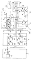
- the figure shows a power amplifier for a defibrillator, in particular a portable external automatic defibrillator (AED), with a charging device 1 and a H-bridge 2 having high voltage part and a coupling circuit connected thereto 3.
- the charging device has a charging part 1.1, for example, an AC voltage source with connected thereto transformer 1.2 for generating a high voltage, with an energy storage in the form of a storage capacitor C or a storage capacitor assembly is loaded with electrical energy for defibrillation via a charging diode 1.3 in a conventional manner.
- the H-bridge 2 has in its direction to the positive pole on the one hand and the negative terminal on the other hand H-limbs respective switching elements 2.1, 2.2, 2.3, 2.4, which are controlled by means of associated drive circuits 2.5, 2.6, 2.7, 2.8, such as in the beginning DE 100 65 104 A1 described in more detail.
- the shunt QZ of the H-bridge 2 is an inductance L1 in the form of a coil or an equivalent circuit part in series with a coupling relay 3.1 of the coupling circuit 3 and in series with a discharge resistor RD, or optionally to this automatically connectable by means of the relay patient electrodes Connections PEA to which patient electrodes PE are connected during operation.
- the discharge resistor RD is, for example, a resistor comparable to the patient impedance with a defined value, for example in the range between 10 and 100 ohms, for example 25 or 50 ohms.
- About the discharge resistance of the energy storage C can be discharged after a definable time of disuse or after defibrillation to ensure a defined state.
- the coupling circuit 3 has, in addition to the relay 3.1, a further relay 3.2 lying between it and the patient electrode terminals PEA, with which the patient electrodes PE can be selectively connected to an ECG measuring device EKG or the H-bridge 2 of the high-voltage part.
- Both relays 3.1, 3.2 can be controlled via respectively associated relay actuators 3.3 and 3.4, wherein the relay control 3.3 in the embodiment shown control circuit resistors R4, R5, a control circuit transistor T1 and a control circuit diode D4 has shown arrangement.
- the further relay control 3.4 has control circuit resistors R6, R7, R8, two control circuit transistors T2, T3 and a control circuit diode in the arrangement shown.
- the coupling circuit 3 is equipped with a relay test device for the coupling relay 3.1.
- the relay test device is used to test the relay 3.1, wherein the high voltage part, in the present case the H-bridge 2 is switched off by appropriate control of the switching elements 2.1, 2.2, 2.3, 2.4.
- a test supply voltage UT provided separately for the relay test is provided by a test supply voltage device of the order of a few or a few tens of volts, for example between 6 and 30 volts.
- the relay test device is constructed so that when connected to the relay 3.1 discharge resistor RD a closed circuit from the positive terminal of the test supply voltage UT via a first resistor arrangement RI with multiple resistors on the discharge resistor RD, the corresponding contacts of the relay 3.1 and a further resistor arrangement RII is formed with several resistors to ground GND.
- a measuring branch ME with measuring circuit resistors R1, R2, R3 and measuring circuit diodes D1, D2, D3 and a comparator circuit K is formed between the positive terminal of the test supply voltage UT and the first resistor arrangement RI, the measuring circuit resistor R1 is in a current path leading to an input terminal of the comparator circuit K, the measuring circuit resistor R2 between the first measuring circuit resistor R1 and the input terminal of the comparator circuit K is grounded and the third measuring circuit resistor R3 at the output of the comparator circuit K to a predetermined Potential is guided.
- the measuring circuit diodes D1, D2 are stabilizing Zener diodes and grounded in front of the first measuring circuit resistor R1 while the third measuring circuit diode D3 is grounded parallel to the second measuring circuit resistor R2.
- At the second input terminal of the comparator K is a predetermined or predetermined comparison voltage.
- the discharge resistor RD is connected to the relay 3.1 in the respective current path, flows from one of the positive pole of the test supply voltage UT to the branch point of the measuring branch ME present total current I1 a partial current I4 through the relay 3.1, while another partial current as the measuring current I3 flows through the measuring branch ME via the second measuring circuit resistor R2 to ground and generates at this a corresponding voltage drop, which results in the connected state of the relay 3.1 a state corresponding to this comparison voltage.
- the discharge resistor RD is not connected by appropriate control of the relay 3.1, the total current I1 flows as measuring current I2 through the measuring branch ME and generates at the second measuring circuit resistor R2 a correspondingly higher voltage drop, which can be detected by means of the comparator circuit K.
- the measuring branch ME can therefore be distinguished between a connected and non-connected state of the discharge resistor RD and thus infer the proper operation of the relay 3.1, including the output of the comparator K is evaluated in an appropriate evaluation.
- Relay 3.1 can be distinguished, as far as such evaluation is desired. Because of the separate test supply voltage UT, the relay test device is independent of the high voltage part, so that a reliable statement about the relay functionality is made possible.
- the control circuit of the defibrillator is designed so that it connects the high-voltage part with the patient electrodes PE only with proper operation of the relay 3.1. This function can then also be realized, for example, by controlling the further relay 3.2 so that it interrupts the connection between the patient electrodes PE and the patient electrode terminals PEA to the high-voltage part when a fault condition of the coupling relay 3.1 is detected.
- the evaluation can be carried out in a suitable logic circuit, eg a programmed microcontroller or another programmable logic unit (CPLD) and used for further control tasks.
- CPLD programmable logic unit
Landscapes
- Health & Medical Sciences (AREA)
- Cardiology (AREA)
- Heart & Thoracic Surgery (AREA)
- Engineering & Computer Science (AREA)
- Biomedical Technology (AREA)
- Nuclear Medicine, Radiotherapy & Molecular Imaging (AREA)
- Radiology & Medical Imaging (AREA)
- Life Sciences & Earth Sciences (AREA)
- Animal Behavior & Ethology (AREA)
- General Health & Medical Sciences (AREA)
- Public Health (AREA)
- Veterinary Medicine (AREA)
- Electrotherapy Devices (AREA)
- Selective Calling Equipment (AREA)
Description
- Die Erfindung bezieht sich auf einen Defibrillator mit einer Endstufe, die einen Hochspannungsteil und mit diesem mittels einer Ankoppelschaltung automatisch über ein Relais verbindbare Patientenelektroden-Anschlüsse sowie eine Relais-Testeinrichtung aufweist, und zwar insbesondere einen tragbaren externen Defibrillator.
- Ein derartiger Defibrillator ist in der EP 0 946 956 B1 angegeben. Bei diesem bekannten Defibrillator ist ein Verfahren vorgesehen, mit dem ein Relais getestet wird, das in einer Ankoppelschaltung zwischen einem Hochspannungsteil und Patientenelektroden angeordnet ist und einerseits in eine offene Stellung und andererseits in eine geschlossene Stellung, in der die Patientenelektroden mit dem Hochspannungsteil verbunden sind, bringbar ist. Zum Testen des Relais wird ein Testablauf durchgeführt, bei dem eine Entladung eines Energiespeichers in Form eines die Energie für den Defibrillationsimpuls speichernden Kondensators über das Relais und die Patientenelektroden vorgenommen und die Spannung an dem Kondensator gemessen wird. Die Spannung des Kondensators während der Entladung wird mit einer Schwellenspannung verglichen, um auf den Relaiszustand zurückzuschließen. Es ist schwierig, auf diese Weise in unterschiedlichen Situationen eine zuverlässige Aussage über den Relaiszustand herzuleiten.
- Ein insbesondere tragbarer automatischer externer Defibrillator (AED) mit einem besonders ausgebildeten Hochspannungsteil mit H-Brücke und in deren Querzweig in Reihe zu einer Induktivität (Spule oder äquivalentes Bauteil) angeschlossenen Patientenelektroden ist in der DE 100 65 104 A1 angegeben. Bei diesem bekannten Defibrillator können vorteilhaft biphasische Defibrillationsimpulse durch entsprechende Steuerung von Schaltgliedern der H-Brücke erzeugt werden. Ein Relaistest ist dabei nicht angegeben.
- Die US 5,879,374 offenbart einen Defibrillator gemäß dem Oberbegriff des Anspruchs 1. Bei diesem Defibrillator ist eine Relais-Testeinrichtung vorhanden, die jedoch nicht den Zustand der Entladewiderstandsanordnung einbezieht.
- Der Erfindung liegt die Aufgabe zugrunde, einen insbesondere tragbaren externen Defibrillator der eingangs genannten Art bereit zu stellen, mit dem die Prüfung des Ankoppelrelais möglichst zuverlässig durchführbar ist.
- Diese Aufgabe wird mit den Merkmalen des Anspruches 1 gelöst. Hiernach ist vorgesehen, dass eine Entladewiderstandsanordnung vorhanden ist, auf die mittels des Relais anstelle der Patientenelektroden-Anschlüsse automatisch umschaltbar ist und dass die Relais-Testeinrichtung zum Testen des Relais unter Einbeziehung des Zustandes der anliegenden Entladewiderstandsanordnung ausgebildet ist.
- Durch die angeschlossene Entladewiderstandsanordnung werden zuverlässige Bedingungen zum Testen des Relais geschaffen, so dass eine zuverlässige Auswertung des Relaiszustandes erreicht wird.
- Die zuverlässige Prüfung des Ankoppel-Relais wird dadurch begünstigt, dass die Relais-Testeinrichtung eine eigene Spannungsversorgung für eine Test-Versorgungsspannung aufweist, mit der zum Testen des Relais bei angeschlossener Entladewiderstandsanordnung ein Strom durch das Relais bewirkbar ist, wobei ein Strom von dem Hochspannungsteil unterbunden ist. Diese Maßnahmen tragen zu eindeutigen Testbedingungen bei, wobei ein einfacher Aufbau der Messeinrichtung realisierbar ist.
- Eine weitere vorteilhafte Ausgestaltung der Relais-Testeinrichtung besteht darin, dass sie einen Messzweig aufweist, in dem bei anliegender Entladewiderstandsanordnung einerseits und bei nicht anliegender Entladewiderstandsanordnung andererseits unterschiedliche Spannungen oder Messströme anliegen, die beim Testen des Relais einbeziehbar sind.
- Hierbei wird eine zuverlässige Messung dadurch unterstützt, dass der Messzweig eine Messverstärkerschaltung zum Bilden eines Messwerts für einen Relaiszustand aufweist.
- Eindeutige Aussagen werden ferner dadurch begünstigt, dass die Messverstärkerschaltung einen Komparator zum Vergleichen mit einem Sollwert aufweist.
- Ein vorteilhafter Aufbau des Defibrillators mit der Relais-Testeinrichtung besteht ferner darin, dass der Hochspannungsteil eine von einem Energiespeicher mit Hochspannung für einen Defibrillationsimpuls beaufschlagbare H-Brücke mit steuerbaren Schaltgliedern in den H-Schenkeln aufweist und dass das Relais in Reihe mit einer Induktivität und einerseits dem Entladewiderstand oder andererseits den an die Patientenelektroden-Anschlüsse angeschlossenen Patientenelektroden in dem Querzweig der H-Brücke angeordnet ist.
- Eine weitere vorteilhafte Ausgestaltung des Defibrillators mit der Relais-Testeinrichtung besteht darin, dass zwischen dem Relais und den Patientenelektroden-Anschlüssen ein weiteres Relais eingebunden ist, mit dem die Patientenelektroden wahlweise mit dem Hochspannungsteil oder einer EKG-Messeinrichtung verbindbar sind.
- Die Erfindung wird nachfolgend anhand eines Ausführungsbeispiels unter Bezugnahme auf die Zeichnung näher erläutert.
- Die Fig. zeigt eine Endstufe für einen Defibrillator, insbesondere einen tragbaren externen automatischen Defibrillator (AED), mit einem eine Ladeeinrichtung 1 und eine H-Brücke 2 aufweisenden Hochspannungsteil sowie einer daran angeschlossenen Ankoppelschaltung 3. Die Ladeeinrichtung weist einen Ladeteil 1.1, beispielsweise eine Wechselspannungsquelle, mit daran angeschlossenem Transformator 1.2 zum Erzeugen einer Hochspannung auf, mit der über eine Ladediode 1.3 in an sich bekannter Weise ein Energiespeicher in Form eines Speicherkondensators C oder einer Speicherkondensatoranordnung mit elektrischer Energie für die Defibrillation geladen wird. Die H-Brücke 2 weist in ihren zu dem Pluspol einerseits und dem Minuspol andererseits gerichteten H-Schenkeln jeweilige Schaltglieder 2.1, 2.2, 2.3, 2.4 auf, die mittels zugeordneter Ansteuerschaltungen 2.5, 2.6, 2.7, 2.8 angesteuert werden, wie beispielsweise in der eingangs genannten DE 100 65 104 A1 näher beschrieben. Als Besonderheit ist bei vorliegender H-Brücke 2 antiparallel zu zwei Schaltgliedern 2.3, 2.4, von denen eines in einem zu dem Pluspol führenden H-Schenkel und eines in dem gegenüberliegenden, zum Minuspol führenden H-Schenkel angeordnet ist, jeweils eine Diodenanordnung 2.9, 2.10 angeordnet, um eine zuverlässige Funktion der Schaltglieder 2.1, 2.2, 2.3, 2.4 bei biphasischem Betrieb durch Freilauf zu gewährleisten, insbesondere wenn Schaltvorgänge höherer Frequenz von z.B. 10 kHz oder mehr zur Regelung der Pulsenergie beispielsweise mittels Stromregelung durchgeführt werden. In dem Querzweig QZ der H-Brücke 2 liegt eine Induktivität L1 in Form einer Spule oder eines äquivalenten Schaltungsteils in Reihe zu einem Ankoppel-Relais 3.1 der Ankoppelschaltung 3 sowie in Reihe zu einem Entladewiderstand RD, oder wahlweise zu diesem mittels des Relais automatisch anschließbaren Patientenelektroden-Anschlüssen PEA, an die im Betrieb Patientenelektroden PE angeschlossen sind. Bei dem Entladewiderstand RD handelt es sich beispielsweise um einen der Patientenimpedanz vergleich-baren Widerstand mit einem definierten Wert z.B. im Bereich zwischen 10 und 100 Ohm, beispielsweise 25 oder 50 Ohm. Über den Entladewiderstand kann der Energiespeicher C nach einer festlegbaren Zeit des Nichtgebrauchs oder nach einer Defibrillation zum Gewährleisten eines definierten Zustandes entladen werden.
- Die Ankoppelschaltung 3 weist außer dem Relais 3.1 ein zwischen diesem und den Patientenelektroden-Anschlüssen PEA liegendes weiteres Relais 3.2 auf, mit dem die Patientenelektroden PE wahlweise mit einer EKG-Messeinrichtung EKG oder der H-Brücke 2 des Hochspannungsteils verbindbar sind. Beide Relais 3.1, 3.2 sind über jeweils zugeordnete Relaisansteuerungen 3.3 bzw. 3.4 ansteuerbar, wobei die Relaisansteuerung 3.3 bei dem gezeigten Ausführungsbeispiel Steuerkreis-Widerstände R4, R5, einen Steuerkreis-Transistor T1 sowie eine Steuerkreis-Diode D4 in gezeigter Anordnung aufweist. Die weitere Relaisansteuerung 3.4 weist Steuerkreis-Widerstände R6, R7, R8, zwei Steuerkreis-Transistoren T2, T3 sowie eine Steuerkreis-Diode in gezeigter Anordnung auf.
- Mit den Relaisansteuerungen 3.3, 3.4, die auch in anderer Weise aufgebaut sein können, können die beiden Relais 3.1, 3.2 zwischen den gezeigten Schaltstellungen umgesteuert werden.
- Weiterhin ist die Ankoppelschaltung 3 mit einer Relais-Testeinrichtung für das Ankoppel-Relais 3.1 ausgestattet. Die Relais-Testeinrichtung dient zum Prüfen des Relais 3.1, wobei der Hochspannungsteil, und zwar vorliegend die H-Brücke 2 durch entsprechende Ansteuerung der Schaltglieder 2.1, 2.2, 2.3, 2.4 stromlos geschaltet ist. Stattdessen wird eine für den Relais-Test gesondert vorgesehene Test-Versorgungsspannung UT von einer Test-Versorgungsspannungseinrichtung in der Größenordnung einiger oder einiger 10 Volt, z.B. zwischen 6 und 30 Volt bereitgestellt. Die Relais-Testeinrichtung ist so aufgebaut, dass bei an das Relais 3.1 angeschlossenem Entladewiderstand RD ein geschlossener Stromkreis von dem Pluspol der Testversorgungsspannung UT über eine erste Widerstandsanordnung RI mit mehreren Widerständen über den Entladewiderstand RD, die entsprechenden Kontakte des Relais 3.1 und eine weitere Widerstandsanordnung RII mit mehreren Widerständen nach Masse GND gebildet ist. Parallel zu diesem Strompfad ist zwischen dem Pluspol der Test-Versorgungsspannung UT und der ersten Widerstandsanordnung RI ein Messzweig ME mit Messkreis-Widerständen R1, R2, R3 und Messkreis-Dioden D1, D2, D3 und einer Komparatorschaltung K gebildet, wobei der Messkreis-Widerstand R1 in einem zu einem Eingangsanschluss der Komparatorschaltung K führenden Strompfad liegt, der Messkreis-Widerstand R2 zwischen dem ersten Messkreis-Widerstand R1 und dem Eingangsanschluss der Komparatorschaltung K gegen Masse geführt ist und der dritte Messkreis-Widerstand R3 am Ausgang der Komparatorschaltung K zu einem vorgegebenen Potential geführt ist. Die Messkreis-Dioden D1, D2 sind als stabilisierende Zener-Dioden ausgeführt und vor dem ersten Messkreis-Widerstand R1 gegen Masse geführt, während die dritte Messkreis-Diode D3 parallel zu dem zweiten Messkreis-Widerstand R2 nach Masse geführt ist. An dem zweiten Eingangsanschluss der Komparatorschaltung K liegt eine vorgegebene oder vorgebbare Vergleichsspannung.
- Ist der Entladewiderstand RD mit dem Relais 3.1 in dem betreffenden Strompfad angeschlossen, fließt von einem von dem Pluspol der Testversorgungsspannung UT bis zu dem Abzweigpunkt des Messzweiges ME vorliegenden Gesamtstrom I1 ein Teil-Strom I4 durch das Relais 3.1, während ein weiterer Teilstrom als Messstrom I3 durch den Messzweig ME über den zweiten Messkreis-Widerstand R2 nach Masse fließt und an diesem einen entsprechenden Spannungsabfall erzeugt, der im angeschlossenen Zustand des Relais 3.1 eine diesem Zustand entsprechende Vergleichsspannung ergibt.
- Ist der Entladewiderstand RD durch entsprechende Ansteuerung des Relais 3.1 nicht angeschlossen, fließt der Gesamtstrom I1 als Messstrom I2 durch den Messzweig ME und erzeugt an dem zweiten Messkreis-Widerstand R2 einen entsprechend höheren Spannungsabfall, der mittels der Komparatorschaltung K feststellbar ist. Mit dem Messzweig ME kann also zwischen einem angeschlossenen und nicht angeschlossenen Zustand des Entladewiderstandes RD unterschieden und somit auf die ordnungsgemäße Funktion des Relais 3.1 rückgeschlossen werden, wozu das Ausgangssignal der Komparatorschaltung K in einer Auswerteschaltung geeignet ausgewertet wird.
- Auch andere Verstärkerschaltungen in dem Messzweig ME sind denkbar, wobei beispielsweise auch nicht vollständig geschlossene und vollständig offene Zustände des Relais 3.1 unterschieden werden können, soweit eine derartige Auswertung erwünscht ist. Wegen der gesonderten Test-Versorgungsspannung UT ist die Relais-Testeinrichtung unabhängig von dem Hochspannungsteil, so dass eine zuverlässige Aussage über die Relais-Funktionsfähigkeit ermöglicht wird. Die Steuerschaltung des Defibrillators ist so ausgebildet, dass sie nur bei ordnungsgemäßer Funktion des Relais 3.1 den Hochspannungsteil mit den Patientenelektroden PE verbindet. Diese Funktion kann dann beispielsweise auch dadurch realisiert werden, dass das weitere Relais 3.2 so angesteuert wird, dass dieses die Verbindung zwischen den Patientenelektroden PE bzw. den Patientenelektroden-Anschlüssen PEA mit dem Hochspannungsteil unterbricht, wenn ein Fehlerzustand des Koppel-Relais 3.1 festgestellt wird. Die Auswertung kann in einer geeigneten Logikschaltung, z.B. einem programmierten Mikrocontroller oder einer anderen programmierbaren Logikeinheit (CPLD) erfolgen und für weitere Steueraufgaben genützt werden.
Claims (7)
- Defibrillator mit einer Endstufe, die einen Hochspannungsteil (1, 2) und mit diesem mittels einer Ankoppelschaltung (3) automatisch über ein Relais (3.1) verbindbare Patientenelektroden-Anschlüsse (PEA) sowie eine Relais-Testeinrichtung aufweist,
wobei eine Entladewiderstandsanordnung (RD) vorhanden ist, auf die mittels des Relais (3.1) anstelle der Patientenelektroden-Anschlüsse (PEA) automatisch umschaltbar ist, dadurch gekennzeichnet, dass die Relais-Testeinrichtung zum Testen des Relais (3.1) unter Einbeziehung des Zustandes der anliegenden Entladewiderstandsanordnung (RD) ausgebildet ist. - Defibrillator nach Anspruch 1,
dadurch gekennzeichnet,
dass die Relais-Testeinrichtung eine eigene Spannungsversorgung für eine Test-Versorgungsspannung (UT) aufweist, mit der zum Testen des Relais (3.1) bei angeschlossener Entladewiderstandsanordnung (RD) ein Strom (I4) durch das Relais (3.1) bewirkbar ist, wobei ein Strom von dem Hochspannungsteil (1, 2) her unterbunden ist. - Defibrillator nach Anspruch 1 oder 2,
dadurch gekennzeichnet, dass die Relais-Testeinrichtung einen Messzweig (ME) aufweist, in dem bei anliegender Entladewiderstandsanordnung (RD) einerseits und bei nicht anliegender Entladewiderstandsanordnung (RD) andererseits unterschiedliche Spannungen oder Messströme (I3, I2) anliegen, die beim Testen des Relais (3.1) einbeziehbar sind. - Defibrillator nach Anspruch 3,
dadurch gekennzeichnet, dass der Messzweig (ME) eine Messverstärkerschaltung zum Bilden eines Messwerts für einen Relaiszustand aufweist. - Defibrillator nach Anspruch 4,
dadurch gekennzeichnet, dass die Messverstärkerschaltung einen Komparator zum Vergleichen mit einem Sollwert aufweist. - Defibrillator nach einem der vorhergehenden Ansprüche,
dadurch gekennzeichnet,
dass der Hochspannungsteil eine von einem Energiespeicher (C) mit Hochspannung für einen Defibrillationsimpuls beaufschlagbare H-Brücke (2) mit steuerbaren Schaltgliedern (2.1, 2.2, 2.3, 2.4) in den H-Schenkeln aufweist und
dass das Relais (3.1) in Reihe mit einer Induktivität (L1) und einerseits dem Entladewiderstand (RD) oder andererseits den an die Patientenelektroden-Anschlüsse (PEA) angeschlossenen Patientenelektroden (PE) in dem Querzweig (QZ) der H-Brücke (2) angeordnet ist. - Defibrillator nach einem der vorhergehenden Ansprüche,
dadurch gekennzeichnet,
dass zwischen dem Relais (3.1) und den Patientenelektroden-Anschlüssen (PEA) ein weiteres Relais (3.2) eingebunden ist, mit dem die Patientenelektroden (PE) wahlweise mit dem Hochspannungsteil (1, 2) oder einer EKG-Messeinrichtung (EKG) verbindbar sind.
Applications Claiming Priority (3)
| Application Number | Priority Date | Filing Date | Title |
|---|---|---|---|
| DE10254482 | 2002-11-19 | ||
| DE10254482A DE10254482B4 (de) | 2002-11-19 | 2002-11-19 | Defibrillator |
| PCT/EP2003/012855 WO2004045712A1 (de) | 2002-11-19 | 2003-11-17 | Defibrillator mit einer relais-testeinrichtung |
Publications (2)
| Publication Number | Publication Date |
|---|---|
| EP1565234A1 EP1565234A1 (de) | 2005-08-24 |
| EP1565234B1 true EP1565234B1 (de) | 2006-09-27 |
Family
ID=32318618
Family Applications (1)
| Application Number | Title | Priority Date | Filing Date |
|---|---|---|---|
| EP03767564A Expired - Lifetime EP1565234B1 (de) | 2002-11-19 | 2003-11-17 | Defibrillator mit einer relais-testeinrichtung |
Country Status (6)
| Country | Link |
|---|---|
| US (1) | US20060036287A1 (de) |
| EP (1) | EP1565234B1 (de) |
| AT (1) | ATE340604T1 (de) |
| DE (2) | DE10254482B4 (de) |
| ES (1) | ES2274279T3 (de) |
| WO (1) | WO2004045712A1 (de) |
Cited By (1)
| Publication number | Priority date | Publication date | Assignee | Title |
|---|---|---|---|---|
| RU2645244C2 (ru) * | 2016-06-15 | 2018-02-19 | Общество с ограниченной ответственностью Концерн "Аксион" (ООО Концерн "Аксион") | Дефибриллятор |
Families Citing this family (2)
| Publication number | Priority date | Publication date | Assignee | Title |
|---|---|---|---|---|
| DE202012100155U1 (de) | 2012-01-17 | 2012-02-23 | Metrax Gmbh | Relais |
| CN110520190A (zh) * | 2017-04-27 | 2019-11-29 | 维曼急救医疗科技两合公司 | 用于除颤的方法和设备 |
Family Cites Families (7)
| Publication number | Priority date | Publication date | Assignee | Title |
|---|---|---|---|---|
| US5097830A (en) * | 1990-03-30 | 1992-03-24 | Laerdal Manufacturing Corporation | Defibrillator with reliability verification |
| US5275158A (en) * | 1992-02-21 | 1994-01-04 | Zmd Corporation | Defibrillation electrode switch condition sensing |
| US5879374A (en) * | 1993-05-18 | 1999-03-09 | Heartstream, Inc. | External defibrillator with automatic self-testing prior to use |
| US5431684A (en) * | 1993-12-22 | 1995-07-11 | Ventritex, Inc. | Implantable defibrillator output stage test circuit and method |
| US5748427A (en) * | 1996-12-19 | 1998-05-05 | Physio-Control Corporation | Method and system for detecting relay failure |
| US5873893A (en) * | 1997-03-05 | 1999-02-23 | Physio-Control Corporation | Method and apparatus for verifying the integrity of an output circuit before and during application of a defibrillation pulse |
| DE10064965B4 (de) | 1999-12-29 | 2007-01-04 | Metrax Gmbh | Medizinisches Gerät zum Beaufschlagen eines Patienten mit elektrischer Energie |
-
2002
- 2002-11-19 DE DE10254482A patent/DE10254482B4/de not_active Expired - Fee Related
-
2003
- 2003-11-17 ES ES03767564T patent/ES2274279T3/es not_active Expired - Lifetime
- 2003-11-17 US US10/535,592 patent/US20060036287A1/en not_active Abandoned
- 2003-11-17 WO PCT/EP2003/012855 patent/WO2004045712A1/de not_active Ceased
- 2003-11-17 AT AT03767564T patent/ATE340604T1/de not_active IP Right Cessation
- 2003-11-17 DE DE50305204T patent/DE50305204D1/de not_active Expired - Lifetime
- 2003-11-17 EP EP03767564A patent/EP1565234B1/de not_active Expired - Lifetime
Cited By (1)
| Publication number | Priority date | Publication date | Assignee | Title |
|---|---|---|---|---|
| RU2645244C2 (ru) * | 2016-06-15 | 2018-02-19 | Общество с ограниченной ответственностью Концерн "Аксион" (ООО Концерн "Аксион") | Дефибриллятор |
Also Published As
| Publication number | Publication date |
|---|---|
| ES2274279T3 (es) | 2007-05-16 |
| DE10254482A1 (de) | 2004-06-17 |
| ATE340604T1 (de) | 2006-10-15 |
| DE10254482B4 (de) | 2008-06-05 |
| WO2004045712A1 (de) | 2004-06-03 |
| DE50305204D1 (de) | 2006-11-09 |
| US20060036287A1 (en) | 2006-02-16 |
| EP1565234A1 (de) | 2005-08-24 |
Similar Documents
| Publication | Publication Date | Title |
|---|---|---|
| DE2850841C2 (de) | Schaltungsanordnung für ein integrierbares elektronisches Relais | |
| DE3718941A1 (de) | Vorrichtung und verfahren zur einleitung von hochspannungsstroemen in eine chemische loesung | |
| EP0569609A1 (de) | Defibrillationsgerät | |
| DE3941885A1 (de) | Stromversorgungseinrichtung mit unsymmetrieueberwachungsschaltung | |
| EP1169763A1 (de) | Schutzschaltung für ein elektronisches gerät | |
| DE1463662A1 (de) | Elektrisches Stromversorgungsgeraet | |
| EP1565234B1 (de) | Defibrillator mit einer relais-testeinrichtung | |
| EP0097233B1 (de) | Schaltungsanordnung zur Inbetriebnahme der Fernspeisung von elektrischen Verbrauchern | |
| DE2647569B2 (de) | Impulsgenerator mit umschaltbarer Ausgangsfrequenz | |
| EP0348587A2 (de) | Schaltungsanordnung zur Überwachung eines aus einem integrierten Schaltkreis aufgebauten elektronischen Gerätes gegen Betriebsstörungen | |
| DE3237198C2 (de) | Herzschrittmacher mit direkt gekoppelter Ausgangsstufe | |
| CH675637A5 (de) | ||
| DE102004058671A1 (de) | Elektrische Schaltung zur Ansteuerung eines piezoelektrischen Elements insbesondere einer Kraftstoffeinspritzanlage eines Kraftfahrzeugs | |
| EP0111168B1 (de) | Schaltungsanordnung zur Fehlerortung in Verbindung mit einer Einrichtung zur Fernspeisung von elektrischen Verbrauchern | |
| DE10064965B4 (de) | Medizinisches Gerät zum Beaufschlagen eines Patienten mit elektrischer Energie | |
| DE2352381B2 (de) | Impulsgeber | |
| DE1588249A1 (de) | Schaltungsanordnung zur Drehzahlregelung eines Gleichstrommotors | |
| DE102018126179B4 (de) | Prüfeinrichtung zum Prüfen eines Prüfobjektes, insbesondere eines Impedanz-behafteten Prüfobjektes mit vollständiger Eigendiagnosefähigkeit | |
| DE3732861A1 (de) | Schaltungsanordnung zum schutz niederohmiger ausgaenge | |
| DE1638529B2 (de) | Elektronische schalteinrichtung mit einem triac | |
| DE2837450C3 (de) | Verfahren und Schaltungsanordnung zum Steuern eines Bolzenschweißgeräts | |
| DE1513265C (de) | Gleichstrom Uberlastungsschutzschal tung | |
| DE102022110812A1 (de) | Sicherheitsschaltvorrichtung insbesondere zum überwachten Einschalten eines elektrischen und/oder elektronischen Verbrauchers | |
| DE2725086C3 (de) | Vorrichtung zur Überprüfung des Vorhandenseins einer elektrischen Spannung an Teilen elektrischer Anlagen | |
| CH681356A5 (en) | Electromagnetic screening mat for bed mattresses |
Legal Events
| Date | Code | Title | Description |
|---|---|---|---|
| PUAI | Public reference made under article 153(3) epc to a published international application that has entered the european phase |
Free format text: ORIGINAL CODE: 0009012 |
|
| 17P | Request for examination filed |
Effective date: 20050620 |
|
| AK | Designated contracting states |
Kind code of ref document: A1 Designated state(s): AT BE BG CH CY CZ DE DK EE ES FI FR GB GR HU IE IT LI LU MC NL PT RO SE SI SK TR |
|
| GRAP | Despatch of communication of intention to grant a patent |
Free format text: ORIGINAL CODE: EPIDOSNIGR1 |
|
| GRAS | Grant fee paid |
Free format text: ORIGINAL CODE: EPIDOSNIGR3 |
|
| GRAA | (expected) grant |
Free format text: ORIGINAL CODE: 0009210 |
|
| AK | Designated contracting states |
Kind code of ref document: B1 Designated state(s): AT BE BG CH CY CZ DE DK EE ES FI FR GB GR HU IE IT LI LU MC NL PT RO SE SI SK TR |
|
| PG25 | Lapsed in a contracting state [announced via postgrant information from national office to epo] |
Ref country code: IT Free format text: LAPSE BECAUSE OF FAILURE TO SUBMIT A TRANSLATION OF THE DESCRIPTION OR TO PAY THE FEE WITHIN THE PRESCRIBED TIME-LIMIT;WARNING: LAPSES OF ITALIAN PATENTS WITH EFFECTIVE DATE BEFORE 2007 MAY HAVE OCCURRED AT ANY TIME BEFORE 2007. THE CORRECT EFFECTIVE DATE MAY BE DIFFERENT FROM THE ONE RECORDED. Effective date: 20060927 Ref country code: CZ Free format text: LAPSE BECAUSE OF FAILURE TO SUBMIT A TRANSLATION OF THE DESCRIPTION OR TO PAY THE FEE WITHIN THE PRESCRIBED TIME-LIMIT Effective date: 20060927 Ref country code: NL Free format text: LAPSE BECAUSE OF FAILURE TO SUBMIT A TRANSLATION OF THE DESCRIPTION OR TO PAY THE FEE WITHIN THE PRESCRIBED TIME-LIMIT Effective date: 20060927 Ref country code: RO Free format text: LAPSE BECAUSE OF FAILURE TO SUBMIT A TRANSLATION OF THE DESCRIPTION OR TO PAY THE FEE WITHIN THE PRESCRIBED TIME-LIMIT Effective date: 20060927 Ref country code: SI Free format text: LAPSE BECAUSE OF FAILURE TO SUBMIT A TRANSLATION OF THE DESCRIPTION OR TO PAY THE FEE WITHIN THE PRESCRIBED TIME-LIMIT Effective date: 20060927 Ref country code: SK Free format text: LAPSE BECAUSE OF FAILURE TO SUBMIT A TRANSLATION OF THE DESCRIPTION OR TO PAY THE FEE WITHIN THE PRESCRIBED TIME-LIMIT Effective date: 20060927 Ref country code: FI Free format text: LAPSE BECAUSE OF FAILURE TO SUBMIT A TRANSLATION OF THE DESCRIPTION OR TO PAY THE FEE WITHIN THE PRESCRIBED TIME-LIMIT Effective date: 20060927 Ref country code: IE Free format text: LAPSE BECAUSE OF FAILURE TO SUBMIT A TRANSLATION OF THE DESCRIPTION OR TO PAY THE FEE WITHIN THE PRESCRIBED TIME-LIMIT Effective date: 20060927 |
|
| REG | Reference to a national code |
Ref country code: GB Ref legal event code: FG4D Free format text: NOT ENGLISH |
|
| REG | Reference to a national code |
Ref country code: CH Ref legal event code: EP |
|
| REG | Reference to a national code |
Ref country code: IE Ref legal event code: FG4D Free format text: LANGUAGE OF EP DOCUMENT: GERMAN |
|
| REF | Corresponds to: |
Ref document number: 50305204 Country of ref document: DE Date of ref document: 20061109 Kind code of ref document: P |
|
| PG25 | Lapsed in a contracting state [announced via postgrant information from national office to epo] |
Ref country code: BE Free format text: LAPSE BECAUSE OF NON-PAYMENT OF DUE FEES Effective date: 20061130 Ref country code: MC Free format text: LAPSE BECAUSE OF NON-PAYMENT OF DUE FEES Effective date: 20061130 |
|
| PG25 | Lapsed in a contracting state [announced via postgrant information from national office to epo] |
Ref country code: DK Free format text: LAPSE BECAUSE OF FAILURE TO SUBMIT A TRANSLATION OF THE DESCRIPTION OR TO PAY THE FEE WITHIN THE PRESCRIBED TIME-LIMIT Effective date: 20061227 Ref country code: SE Free format text: LAPSE BECAUSE OF FAILURE TO SUBMIT A TRANSLATION OF THE DESCRIPTION OR TO PAY THE FEE WITHIN THE PRESCRIBED TIME-LIMIT Effective date: 20061227 Ref country code: BG Free format text: LAPSE BECAUSE OF FAILURE TO SUBMIT A TRANSLATION OF THE DESCRIPTION OR TO PAY THE FEE WITHIN THE PRESCRIBED TIME-LIMIT Effective date: 20061227 |
|
| REG | Reference to a national code |
Ref country code: CH Ref legal event code: NV Representative=s name: SCHNEIDER FELDMANN AG PATENT- UND MARKENANWAELTE |
|
| NLV1 | Nl: lapsed or annulled due to failure to fulfill the requirements of art. 29p and 29m of the patents act | ||
| PG25 | Lapsed in a contracting state [announced via postgrant information from national office to epo] |
Ref country code: PT Free format text: LAPSE BECAUSE OF FAILURE TO SUBMIT A TRANSLATION OF THE DESCRIPTION OR TO PAY THE FEE WITHIN THE PRESCRIBED TIME-LIMIT Effective date: 20070313 |
|
| REG | Reference to a national code |
Ref country code: IE Ref legal event code: FD4D |
|
| GBV | Gb: ep patent (uk) treated as always having been void in accordance with gb section 77(7)/1977 [no translation filed] |
Effective date: 20060927 |
|
| ET | Fr: translation filed | ||
| REG | Reference to a national code |
Ref country code: ES Ref legal event code: FG2A Ref document number: 2274279 Country of ref document: ES Kind code of ref document: T3 |
|
| PLBE | No opposition filed within time limit |
Free format text: ORIGINAL CODE: 0009261 |
|
| STAA | Information on the status of an ep patent application or granted ep patent |
Free format text: STATUS: NO OPPOSITION FILED WITHIN TIME LIMIT |
|
| 26N | No opposition filed |
Effective date: 20070628 |
|
| PG25 | Lapsed in a contracting state [announced via postgrant information from national office to epo] |
Ref country code: GB Free format text: LAPSE BECAUSE OF FAILURE TO SUBMIT A TRANSLATION OF THE DESCRIPTION OR TO PAY THE FEE WITHIN THE PRESCRIBED TIME-LIMIT Effective date: 20060927 |
|
| BERE | Be: lapsed |
Owner name: METRAX G.M.B.H. Effective date: 20061130 |
|
| PG25 | Lapsed in a contracting state [announced via postgrant information from national office to epo] |
Ref country code: AT Free format text: LAPSE BECAUSE OF NON-PAYMENT OF DUE FEES Effective date: 20061117 |
|
| PG25 | Lapsed in a contracting state [announced via postgrant information from national office to epo] |
Ref country code: GR Free format text: LAPSE BECAUSE OF FAILURE TO SUBMIT A TRANSLATION OF THE DESCRIPTION OR TO PAY THE FEE WITHIN THE PRESCRIBED TIME-LIMIT Effective date: 20061228 |
|
| PG25 | Lapsed in a contracting state [announced via postgrant information from national office to epo] |
Ref country code: EE Free format text: LAPSE BECAUSE OF FAILURE TO SUBMIT A TRANSLATION OF THE DESCRIPTION OR TO PAY THE FEE WITHIN THE PRESCRIBED TIME-LIMIT Effective date: 20060927 |
|
| PG25 | Lapsed in a contracting state [announced via postgrant information from national office to epo] |
Ref country code: HU Free format text: LAPSE BECAUSE OF FAILURE TO SUBMIT A TRANSLATION OF THE DESCRIPTION OR TO PAY THE FEE WITHIN THE PRESCRIBED TIME-LIMIT Effective date: 20070328 Ref country code: TR Free format text: LAPSE BECAUSE OF FAILURE TO SUBMIT A TRANSLATION OF THE DESCRIPTION OR TO PAY THE FEE WITHIN THE PRESCRIBED TIME-LIMIT Effective date: 20060927 Ref country code: LU Free format text: LAPSE BECAUSE OF NON-PAYMENT OF DUE FEES Effective date: 20061117 |
|
| PG25 | Lapsed in a contracting state [announced via postgrant information from national office to epo] |
Ref country code: CY Free format text: LAPSE BECAUSE OF FAILURE TO SUBMIT A TRANSLATION OF THE DESCRIPTION OR TO PAY THE FEE WITHIN THE PRESCRIBED TIME-LIMIT Effective date: 20060927 |
|
| PGFP | Annual fee paid to national office [announced via postgrant information from national office to epo] |
Ref country code: ES Payment date: 20081121 Year of fee payment: 6 |
|
| PGFP | Annual fee paid to national office [announced via postgrant information from national office to epo] |
Ref country code: IT Payment date: 20081120 Year of fee payment: 6 |
|
| PGFP | Annual fee paid to national office [announced via postgrant information from national office to epo] |
Ref country code: FR Payment date: 20081113 Year of fee payment: 6 |
|
| REG | Reference to a national code |
Ref country code: FR Ref legal event code: ST Effective date: 20100730 |
|
| PG25 | Lapsed in a contracting state [announced via postgrant information from national office to epo] |
Ref country code: FR Free format text: LAPSE BECAUSE OF NON-PAYMENT OF DUE FEES Effective date: 20091130 |
|
| PG25 | Lapsed in a contracting state [announced via postgrant information from national office to epo] |
Ref country code: IT Free format text: LAPSE BECAUSE OF NON-PAYMENT OF DUE FEES Effective date: 20091117 |
|
| REG | Reference to a national code |
Ref country code: ES Ref legal event code: FD2A Effective date: 20110331 |
|
| PG25 | Lapsed in a contracting state [announced via postgrant information from national office to epo] |
Ref country code: ES Free format text: LAPSE BECAUSE OF NON-PAYMENT OF DUE FEES Effective date: 20110321 |
|
| PG25 | Lapsed in a contracting state [announced via postgrant information from national office to epo] |
Ref country code: ES Free format text: LAPSE BECAUSE OF NON-PAYMENT OF DUE FEES Effective date: 20091118 |
|
| PGFP | Annual fee paid to national office [announced via postgrant information from national office to epo] |
Ref country code: CH Payment date: 20191121 Year of fee payment: 17 |
|
| REG | Reference to a national code |
Ref country code: CH Ref legal event code: PFA Owner name: METRAX GMBH, DE Free format text: FORMER OWNER: METRAX GMBH, DE |
|
| REG | Reference to a national code |
Ref country code: CH Ref legal event code: PL |
|
| PG25 | Lapsed in a contracting state [announced via postgrant information from national office to epo] |
Ref country code: CH Free format text: LAPSE BECAUSE OF NON-PAYMENT OF DUE FEES Effective date: 20201130 Ref country code: LI Free format text: LAPSE BECAUSE OF NON-PAYMENT OF DUE FEES Effective date: 20201130 |
|
| PGFP | Annual fee paid to national office [announced via postgrant information from national office to epo] |
Ref country code: DE Payment date: 20211129 Year of fee payment: 19 |
|
| REG | Reference to a national code |
Ref country code: DE Ref legal event code: R119 Ref document number: 50305204 Country of ref document: DE |
|
| PG25 | Lapsed in a contracting state [announced via postgrant information from national office to epo] |
Ref country code: DE Free format text: LAPSE BECAUSE OF NON-PAYMENT OF DUE FEES Effective date: 20230601 |