EP1565295B1 - Anordnung zur herstellung von betonformsteinen - Google Patents
Anordnung zur herstellung von betonformsteinen Download PDFInfo
- Publication number
- EP1565295B1 EP1565295B1 EP03811354A EP03811354A EP1565295B1 EP 1565295 B1 EP1565295 B1 EP 1565295B1 EP 03811354 A EP03811354 A EP 03811354A EP 03811354 A EP03811354 A EP 03811354A EP 1565295 B1 EP1565295 B1 EP 1565295B1
- Authority
- EP
- European Patent Office
- Prior art keywords
- insert
- arrangement according
- top plate
- relief
- bottom plate
- Prior art date
- Legal status (The legal status is an assumption and is not a legal conclusion. Google has not performed a legal analysis and makes no representation as to the accuracy of the status listed.)
- Expired - Lifetime
Links
- 239000011456 concrete brick Substances 0.000 title abstract 2
- 229910052751 metal Inorganic materials 0.000 claims abstract description 19
- 239000002184 metal Substances 0.000 claims abstract description 18
- 238000000465 moulding Methods 0.000 claims abstract description 9
- 125000006850 spacer group Chemical group 0.000 claims description 16
- 238000005452 bending Methods 0.000 claims description 13
- 238000013016 damping Methods 0.000 claims description 10
- 238000004519 manufacturing process Methods 0.000 claims description 10
- 239000000463 material Substances 0.000 claims description 9
- 238000003825 pressing Methods 0.000 claims description 3
- 238000003780 insertion Methods 0.000 description 8
- 230000037431 insertion Effects 0.000 description 8
- 239000013013 elastic material Substances 0.000 description 6
- 238000010276 construction Methods 0.000 description 5
- 238000003466 welding Methods 0.000 description 5
- 229910000831 Steel Inorganic materials 0.000 description 3
- 230000000295 complement effect Effects 0.000 description 3
- 238000006073 displacement reaction Methods 0.000 description 3
- 230000013011 mating Effects 0.000 description 3
- 239000010959 steel Substances 0.000 description 3
- 239000000919 ceramic Substances 0.000 description 2
- 238000005520 cutting process Methods 0.000 description 2
- 238000013461 design Methods 0.000 description 2
- 238000011161 development Methods 0.000 description 2
- 230000018109 developmental process Effects 0.000 description 2
- 230000002349 favourable effect Effects 0.000 description 2
- 238000000034 method Methods 0.000 description 2
- 239000004033 plastic Substances 0.000 description 2
- 229920003023 plastic Polymers 0.000 description 2
- 238000012805 post-processing Methods 0.000 description 2
- 238000012545 processing Methods 0.000 description 2
- 238000004873 anchoring Methods 0.000 description 1
- 230000005540 biological transmission Effects 0.000 description 1
- 230000015572 biosynthetic process Effects 0.000 description 1
- 229910010293 ceramic material Inorganic materials 0.000 description 1
- 239000003795 chemical substances by application Substances 0.000 description 1
- 239000002131 composite material Substances 0.000 description 1
- 230000001419 dependent effect Effects 0.000 description 1
- 239000003822 epoxy resin Substances 0.000 description 1
- 238000003698 laser cutting Methods 0.000 description 1
- 239000007769 metal material Substances 0.000 description 1
- 150000002739 metals Chemical class 0.000 description 1
- 238000012986 modification Methods 0.000 description 1
- 230000004048 modification Effects 0.000 description 1
- 238000005192 partition Methods 0.000 description 1
- 229920000647 polyepoxide Polymers 0.000 description 1
- 238000002360 preparation method Methods 0.000 description 1
- 230000002787 reinforcement Effects 0.000 description 1
- 238000005096 rolling process Methods 0.000 description 1
- 238000007493 shaping process Methods 0.000 description 1
- 239000007858 starting material Substances 0.000 description 1
- 239000004575 stone Substances 0.000 description 1
- 239000000758 substrate Substances 0.000 description 1
Images










Classifications
-
- B—PERFORMING OPERATIONS; TRANSPORTING
- B28—WORKING CEMENT, CLAY, OR STONE
- B28B—SHAPING CLAY OR OTHER CERAMIC COMPOSITIONS; SHAPING SLAG; SHAPING MIXTURES CONTAINING CEMENTITIOUS MATERIAL, e.g. PLASTER
- B28B7/00—Moulds; Cores; Mandrels
- B28B7/0002—Auxiliary parts or elements of the mould
- B28B7/0014—Fastening means for mould parts, e.g. for attaching mould walls on mould tables; Mould clamps
-
- B—PERFORMING OPERATIONS; TRANSPORTING
- B28—WORKING CEMENT, CLAY, OR STONE
- B28B—SHAPING CLAY OR OTHER CERAMIC COMPOSITIONS; SHAPING SLAG; SHAPING MIXTURES CONTAINING CEMENTITIOUS MATERIAL, e.g. PLASTER
- B28B1/00—Producing shaped prefabricated articles from the material
- B28B1/08—Producing shaped prefabricated articles from the material by vibrating or jolting
- B28B1/081—Vibration-absorbing means
-
- B—PERFORMING OPERATIONS; TRANSPORTING
- B28—WORKING CEMENT, CLAY, OR STONE
- B28B—SHAPING CLAY OR OTHER CERAMIC COMPOSITIONS; SHAPING SLAG; SHAPING MIXTURES CONTAINING CEMENTITIOUS MATERIAL, e.g. PLASTER
- B28B7/00—Moulds; Cores; Mandrels
- B28B7/0029—Moulds or moulding surfaces not covered by B28B7/0058 - B28B7/36 and B28B7/40 - B28B7/465, e.g. moulds assembled from several parts
-
- B—PERFORMING OPERATIONS; TRANSPORTING
- B28—WORKING CEMENT, CLAY, OR STONE
- B28B—SHAPING CLAY OR OTHER CERAMIC COMPOSITIONS; SHAPING SLAG; SHAPING MIXTURES CONTAINING CEMENTITIOUS MATERIAL, e.g. PLASTER
- B28B7/00—Moulds; Cores; Mandrels
- B28B7/24—Unitary mould structures with a plurality of moulding spaces, e.g. moulds divided into multiple moulding spaces by integratable partitions, mould part structures providing a number of moulding spaces in mutual co-operation
- B28B7/241—Detachable assemblies of mould parts providing only in mutual co-operation a number of complete moulding spaces
Definitions
- the invention relates to an arrangement for the production of concrete blocks.
- a molding machine In which a Garttelform is placed on a vibrating table and filled with concrete mass, which is compacted under the action of pressure and shaking.
- the Studttelformen for larger stone forms such.
- Plant troughs typically have an insert which determines the contour of the molded blocks to be manufactured, and an insert carrier for holding the insert in the molding machine. The insert is welded to the insert carrier.
- the insert carrier with insert is often complex and expensive.
- the US 3,178,791 describes a device for the production of ceramic bodies, in which a mold with a plurality of mold cavities on a substrate deductible and filled with wet ceramic material.
- the mold forms a hollow box, in which the mold cavity walls are held at their upper and lower ends by steel strips laterally in a defined position and connected by epoxy resin to the steel strips.
- the ceramic bodies are fired on the base in an oven.
- the DE 1 584 515 A describes a molding box for the production of concrete blocks, according to the preamble of claim 1.
- the present invention is therefore an object of the invention to provide an arrangement for the production of concrete blocks, which has a simple and inexpensive construction.
- the insert carrier as a hollow box with a cover plate, a base plate spaced therefrom and extending between the base plate and cover plate side walls leads to a low-effort construction of low weight and high stability.
- the insert carrier can be standardized in construction and blanks for the parts forming the box by machine-specific and / or application-specific parameters are easily adaptable to different circumstances.
- the base plate or at least the cover plate is part of an angled sheet having at least three sections.
- the base plate and / or the cover plate continues in the form of an angled sheet after at least two sides of the base plate and the cover plate.
- the box with cover plate, base plate and side walls advantageously consists of two modules, each containing the base plate or cover plate and of which at least one module is designed as an angled, preferably multi-angled sheet metal.
- both modules are U-shaped with two adjacent at opposite edges of the cover plate or base plate side walls, wherein the modules with mutually facing openings of the U-shapes and with respect to the surface normal of base plate and cover plate rotated by 90 ° against each other interlock.
- the components of the box, in particular the cover plate, base plate and side walls containing modules are connected to each other, in particular welded together.
- the structure of the box of angled sheets is particularly advantageous because used as a starting material planar sheets and in these in a cost effective manner, eg. B. by laser beam cutting, contours for the angled plates including the recesses for at least one use can be produced.
- the angled plates are produced by bending a flat sheet metal blank.
- Other techniques for forming a flat sheet metal blank in a body with differently oriented faces are known per se, such as bending by rolling.
- the fold can be cost-effective from flat blanks and three-dimensional structures are produced with high precision, which are then assembled, in particular in the form of only two modules, complementary to the box, in particular welded.
- the design with two U-shaped modules is particularly advantageous in the production at the same time favorable stability properties.
- the modules can be advantageously prefabricated by the high precision in the production of flat sheet metal blanks and their bending so that the modules support each other to sheet metal edges and / or form the edges of welds and / or surfaces mutually fillet welds.
- spacer elements are used, which are advantageously supported on the inner surfaces of the cover plate and the base plate.
- the spacers preferably protrude with projections in openings of the base plate and / or cover plate and can be advantageously welded to the base plate or cover plate in the openings.
- the openings can be conveniently prefabricated already in the flat sheet metal blank.
- the spacers can z. B. be performed in the manner of pins or bolts and selectively support cover plate and base plate.
- the support can also be flat or linear.
- the spacer elements may in particular also be designed as flat or optionally folded sheet metal blanks. Such sheet metal blanks can also be designed as an oblique sheet metal strip and cause by different orientation a stiffening in the manner of a truss.
- the spacer elements are preferably inserted during assembly of the modules forming the box.
- the insert (or possibly the multiple inserts) is advantageously laterally fitted tightly into the recesses of the cover plate and the base plate and horizontally supported by the edges of the recesses.
- the recesses can with available manufacturing techniques, eg. As laser cutting, in the flat blanks are already made in the required size, but can still show a small surcharge for post-processing and edited in a later manufacturing step, in particular only after assembly of the box to its final dimensions.
- the insert is advantageously supported vertically on the base plate and / or cover plate.
- the insert and / or the respective plate advantageously have a structure corresponding to the respective other part in the recess area. Interlocking corresponding structures, for example, gears, projections, depressions, stages u. be a.
- An advantageous embodiment provides for the support of the insert on the inner surface of the base plate and / or cover plate before a step on the edge of the recess and / or on the edge of the insert, the embodiment is preferred with a gradation only along the edge of the insert.
- the insert can be supported vertically on both opposite inner surfaces of the base plate and cover plate according to an advantageous embodiment and is advantageously used for this purpose before the assembly of the box between the base plate and cover plate.
- the edge of the insert then projects at least partially into the recess or preferably beyond it and can be fixed there, in particular welded.
- the insert can also be supported vertically on only one inner surface. Preferably, a vertical support against an outer surface of the base plate and / or cover plate is then additionally given.
- a further advantageous embodiment provides that the insert can be inserted after the assembly of the box from the side of the base plate or from the side of the cover plate through the recesses and then vertically fixed.
- a vertical support is provided on the base plate and / or cover plate, which can advantageously serve as a stop for the insertion of the insert in the box at the same time.
- the support by means of the stop is preferably carried out on the outer surface of the base plate.
- the insert protrudes in the insertion direction over the consideredf kaue of the base plate or cover plate and is fixed in a form-fitting manner after insertion on the outer surface.
- the insert can in particular have a structure that undercuts its edge over the outer surface, preferably a circumferential groove, into which a counter element releasably engages.
- the insert is inserted from below through the base plate forth in the assembled box vertically up to a stop and then surmounted with its upper edge of the cover plate of the box by a measure which is approximately equal to the Thickness of a typically used as a wearing part cover plate is.
- the edge projecting beyond the outer surface of the cover plate then advantageously has an undercut structure, preferably a circumferential groove.
- the cover plate divided into at least two sections contains the counter-structure to the undercut structure, in particular a step edge following the contour of the groove, which inserted parallel to the outer surface in the groove and z. B. is fixed by screwing the cover plate on the cover plate.
- a cover plate or another cover which can be fastened on the cover plate can advantageously also serve to fix core holder strips, which engage in slots in the edge of the insert and continue laterally over the insert in slots of the cover plate, in a form-fitting and preferably detachable manner.
- the insert carrier can in the machine z. B. be held in that flanges for connection to the machine mounted directly on opposite side surfaces of the insert carrier, in particular welded.
- structures for the detachable connection of the insert carrier with separate flange arrangements or with a mold frame can be formed on at least two opposite side walls of the insert carrier.
- Such structures may be formed in a first advantageous embodiment by a introduced into a side wall, in particular milled, substantially horizontal groove, which with a flange-side spring or a flange-side groove and a separate spring a tongue and groove connection for fixing the insert carrier on the flange or form frame forms.
- Another advantageous embodiment of such a structure provides to reshape the side wall into a relief, in particular by multiple fold along preferably horizontal edges.
- the relief obtained by bending in the side wall may in particular form a projection and / or a depression relative to the vertical side wall surface, which corresponds with an appropriately shaped counter-relief on the side of the flange or mold frame and horizontally overlapped with this, so that in horizontal or preferably obliquely Course of a relief surface of the box-side relief over this lying aellesrelief Structure runs and by force on the flange side down the box by force transmission between these surfaces, between which preferably elastic material is inserted, can be pressed onto a base, in particular a vibrating table.
- Box-side relief and flank-side counter-relief may in particular advantageously be triangular in cross-section.
- the preparation of a relief in the side walls of the box by bending a sheet fits particularly favorable in the structure of the box of folded sheets, in particular of two U-shaped bent sheets.
- flange and insert carrier which is particularly adapted to the structure of the insert carrier as a hollow box, provides relief structures are formed in opposite, the flanges facing side walls, which correspond with flange-side counter-relief structures, relief structures and counter-relief structures by horizontal Bracing the Flanschanowskien against the side walls of the box, in particular by means located within the box and connected to the Flanschanowski clamping elements, preferably in turn with oblique contact surfaces and / or interposed elastic material, are pressed against each other.
- These clamping elements can also be inserted through openings in the side walls in an advantageous embodiment.
- a preferred embodiment provides that the clamping elements are designed as strips, which can be inserted through slots in the side walls and brought by rotation in a clamping position in which they can be braced against the side walls from the inside and press them against the flange.
- the flange may also be welded directly to a side wall of the insert carrier in another embodiment.
- Fig. 1 individual components of an advantageous embodiment of the invention in an assembly of an insert carrier with two inserts EI illustrative relative position are shown.
- Essential elements are a basic module GM and a cover module DM.
- the basic module contains a substantially rectangular base plate GP, to which side wall panels SWG connect at two opposite edges.
- Base plate GP and side wall panels SWG are contiguous along the edges KG and the base module is made of a one-piece planar sheet metal blank, preferably by folding at the edges KG.
- the side wall panels are bent at right angles to the plane of the base plate substantially.
- the basic module GM forms an upwardly open U-shape.
- a cover module DM which contains a substantially rectangular cover plate DP and adjoining it at two opposite edges KD side wall panels SWD, made by folding and forms a downwardly open U-shape.
- the side wall panels SWG and SWD are each directed to the other module.
- the U-shapes of base module and cover module are rotated relative to each other by 90 ° with respect to the surface normals of base plate and cover plate.
- the U-shapes can be assembled into a substantially cuboidal box and connected to each other, in particular welded.
- GP recesses AP and in the cover plate DP recesses AD are made, preferably already as parts of the flat sheet metal blank.
- the recesses are provided for receiving the inserts EI and dimensioned, which form between the base plate and cover plate continuous filling spaces for concrete material.
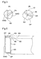
- FIG. 4 shows a section along AA of FIG. 2.
- the assembled U-shaped Abkantbleche basic module and cover module complement each other to a substantially cuboid box with typically different dimensions in the longitudinal direction LR and transverse direction QR and contrast lower height
- a groove FN is introduced, which can serve for holding the insert carrier in a mold frame according to one of several variants.
- a transverse strip QL of a mold frame is indicated on the right, in which the insert carrier facing surface is also a groove RN is introduced.
- spring FE made of metal and / or elastic material releasable vertical attachment of the insert carrier in the mold frame.
- the groove FN can be seen enlarged again in the detail of FIG. 3A.
- This section also shows that the cut edges of the folded sheets of basic module and cover module advantageously form a fillet weld KN, which is particularly advantageous for welding.
- the cut edges may also differ from the outlined simple course and z.
- auxiliary structures for the exact relative positioning of base module and cover module before welding have. Such auxiliary structures and other structures in basic module and cover module may conveniently be advantageously produced in the flat blank before folding.
- the upper edge ER of the insert projects beyond the cover plate DP and has a vertical slot SE.
- a slot SD is also provided in the cover plate DP.
- the aligned slots serve to receive a core holder strip KH, which extends over the entire length of the insert and is attached on both sides.
- a core can be attached, which projects into the filling space of the insert and forms a cavity in the finished concrete block.
- Fig. 4 is an advantageous variant to determine the use in the insert carrier, outlined.
- both the upper and the lower edge region of the insert are set back from the outer surface of the insert and form steps ES, which are supported vertically on the inner surfaces of the cover plate DP and base GP at the edges of the recesses AD and AG, so that the insert clamped between cover plate and base plate is held.
- the steps ES are preferably circumferential around the entire insert.
- the lower edge of the insert protrudes down beyond the base plate and is in operation on a Haittelplatte RP, which z. B. may be the table top of a vibrating table or another plate located thereon, on. about the mold frame, the tongue-and-groove connection and the insert carrier, the insert is pressed during the shaking with high force on the vibrating plate.
- a Haittelplatte RP which z. B. may be the table top of a vibrating table or another plate located thereon, on. about the mold frame, the tongue-and-groove connection and the insert carrier, the insert is pressed during the shaking with high force on the vibrating plate.
- FIG. 6 shows a variant of the vertical fixing of an insert E6 in the insert carrier in which the insert is welded to the insert carrier by means of welds SND, SNG between outer wall of the edge portions of the insert projecting from the insert carrier and the outer surface of cover plate DP or baseplate GP.
- the ABE cover plate is chamfered at the edges surrounding the edge of the insert (AF).
- the insert is not supported vertically on the inner surfaces of the base plate or pressure plate and can be used later.
- the recesses in the flat sheet metal blanks may already have the final size for close embracing the inserts, but can also show a processing material surcharge at the edges, which is removed in a subsequent processing step with greater precision than the sheet blank to the final dimensions, in this Finishing also special edge shapes, z. As chamfers, steps, etc., can be generated.
- Such additional finishing can advantageously together with the introduction of holes in cover plate or base plate, z. B. for screwing the cover plate or for inserting spacers between cover plate and base plate, made.
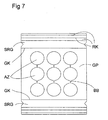
- Fig. 8 shows the sheet of Fig. 7 after bending as a basic module.
- the base plate GP the plurality of recesses AZ and the additional bores BB for the use of spacer elements can be seen.
- the (19mony SGR have after Mehrfachabkantung along the other bending lines RK from the vertical side wall outwardly projecting relief RG in the form of projections with a substantially triangular or trapezoidal course, especially the upwardly facing inclined relief surface RO is particularly advantageous.
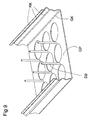
- FIG. 9 the basic module of FIG. 8 is inserted into the bores BB spacer elements DB in the form of z. B. of bolts with in the middle region of larger diameter and at the end regions in the bores BB matching smaller diameter stocked.
- FIG. 10 shows the insert carrier assembled after a cover module which is constructed and manufactured similar to the basic module has been fitted.
- the cover module again has recesses AZ and bores BB, in particular in the cover plate DP, in addition to threaded bores GB for screwing on a cover plate arrangement.
- the threaded holes GB can also be produced only after the assembly of the box of the insert carrier, possibly together with a post-processing of the recesses become.
- the side walls SDR of the deck module also show in the example shown a relief produced by Mehrfachabkantung, which is executed here as a recess SV against the vertical plane of the side wall plate SDR and vertically offset from the projections in the side walls SGR.
- the vertical edges of the side wall panels SGR and SDR are spatially complex following the relief structures, but can be readily specified as lines in the cutting plane for the development in the form of the flat blank.
- the fold can be made sufficiently accurately to ensure a good fit of the two modules to form the approximately cuboid insert carrier.
- Relief structures can also be present on only two opposite sides of the insert carrier, then preferably on the sides facing the flange strips and advantageously on the base plate continuing side walls.
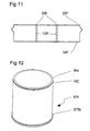
- FIG. 11 shows a sectional view through an assembled insert carrier according to FIG. 10, from which in particular also the position of the spacer elements DB between base plate GP and cover plate DP becomes clear.
- the spacer elements can be welded in the bores BB.
- Fig. 12 shows a circular insert EN, which is pushed from the sides of the base plate GP of the insert carrier through the recesses in the base plate and cover plate and thereby laterally engages closely from the edges of the recesses and is supported horizontally.
- a groove NE is introduced from the outer circumference of the insert, which undercuts the edge and also protrudes beyond the cover plate.
- the groove serves to vertically fix the insert against falling down by a locking member is inserted laterally into the groove.
- Preferably serves as such a locking member is a stepped edge of a cover sheet portion.
- FIG. 13 shows an insert carrier according to FIG. 10 with inserted inserts as well as a covering plate arrangement consisting of several sections ABL, ABR and ABF.
- the sections ABL and ABR each have the inserts half encompassing sheet edges, which complement each other.
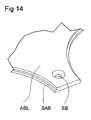
- the sheet edges have a vertical step SAB ( Figure 14) which engages the groove NE in the region of the upper edge of the insert.
- the sections ABL, ABR are placed with a small lateral distance to the inserts on the cover plate and pushed laterally to the inserts. The lateral displacement results in gaps which are closed by the strip-shaped filling sections ABF.
- the sections of the cover plate assembly are screwed onto the cover plate and have prepared holes SB for this purpose.
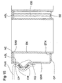
- Fig. 15 shows as a detail in a sectional view of the fixation of an insert in the insert carrier.
- the inserted from below into the base plate insert abuts with the step STN its lower edge region on the outer surface of the base plate GP and is thus prevented from further upward movement.
- Fig. 15 On the left edge in Fig. 15 is still an advantageous embodiment of the holder of the insert carrier of FIG. 13 in a symbolized by a longitudinal or transverse bar mold frame FOR indicated.
- a counter-relief adapted to the relief in the side wall SDR is formed, which has at least one opposing surface opposite the surface RO and horizontally overlapping it. Over these surfaces, between which advantageously elastic material EM with a layer thickness between z. B. 2 mm and 10 mm is inserted, applied during shaking from the mold frame to the insert carrier vertical forces for pressing the lower edge of the insert can be applied to a Rüttelunterlage and Hinttelioloen be allowed in the scope of compressibility of the elastic material.
- the counter-relief in the mold frame preferably supports the relief of the insert carrier as sketched upwards and downwards.
- the formation of a relief in a side wall of an insert carrier to the holder in a mold frame by bending a side wall forming sheet is also independent of the U-shapes of base module and cover module of particular advantage.
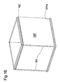
- Fig. 16 is out of a plurality of wall panels WP, which abut along vertical abutting edges SK, built use outlined in which the plurality of wall panels are profiled at their vertical abutting edges so that a displacement of the wall panels is prevented in the direction of the enclosed by them receiving space , After insertion of the assembled insert in the insert carrier is avoided by the tight enclosure in the recesses of the cover plate and base plate evading the wall panels of the enclosed receiving space away.
- the sketched in Fig. 16 Insert shows as the round insert of FIG. 12 is a supporting step in the lower edge region and an undercut groove in the upper edge region.
- Fig. 17 illustrates a further advantageous variant for mounting an insert carrier with side walls SW in a mold frame.
- WA relief modules RMK (FIG. 17A) or RMR (FIG. 17B) are inserted into wall recesses.
- In the direction of the wall surface normal horizontally displaceable counter-relief structures GK and GR of longitudinal and / or transverse strips of a mold frame releasably engage in the relief structures of the relief modules and define the insert carrier in the form of frame in all directions positively.
- Fig. 17A for. B. sketched a self-centering truncated cone shape.
- Fig. 17B the relief structure has a plurality of rotationally symmetric about an axis RA grooves with oblique edges, which are provided with elastic material EM.
- the relief modules and / or the counter-relief structures of the mold frame can be made of steel, other metals, high-strength plastics or combinations of such materials. In particular, between metallic surfaces of relief and counter-relief elastic damping material, in particular be inserted with rubber elastic properties.
- a further advantageous embodiment for holding an insert carrier is outlined in a molding machine, which advantageously dispensed on a use carrier on all sides horizontally surrounding the mold frame and only as an interface to the molding machine flange laterally braced against sidewalls of the insert carrier on opposite transverse sides releasably ,
- clamping elements are applied to the inner walls of the side walls or to supported there elements.
- the clamping elements are braced against flange, so that the outer surface of the side walls of the insert carrier is pressed in the direction of a vertical mating surface of the Flanschanowskien and thereby additionally positively fixed transversely to the surface normal of the mutually pressed surfaces.
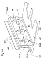
- Fig. 18 an insert carrier for the sake of clarity is opened, z. B. only in the form of a basic module with base GP and side walls SWS sketched.
- the insert carrier is as in the previous examples as a closed box.
- clamping bars SL are arranged via bolts SB, which in the first orientation shown in FIG. 18 fit through insertion openings SA in the side wall SWS of the insert carrier, so that in this position the clamping bars be moved with the flange in the direction of the double arrow and thus in the longitudinal direction LR and z. B. can be introduced from the outside through the insertion into the interior of the box.
- On the inner surface of the side wall SWS several holding contours HK are provided which z. B. can be performed as fitted in retaining recesses of the side wall elements.
- Holding contours and counter contours are preferably in pairs symmetrically to the horizontal axes of rotation BA of the bolt SB.
- the clamping bars SL are brought into the apparent in Fig. 19 position in which holding contours and mating contours directly opposite each other and for planar contact with each other can be brought.
- retaining contours are likewise provided on the outer surface of the side wall and counter-structures GKA (see Fig. 21) corresponding to the wall legs FLW of the flange arrangement are provided.
- the bolts SB are, z. B. by turning on the wall limb FLW externally supported and screwed onto threads of the bolt SB nuts MU, which are visible in the view of FIG.
- the retaining contours HK are embodied as double elements with frustoconical shape fitted in retaining recesses HB of the side wall from both sides.
- the counter contours GKI in the clamping strips SL and GKA in the wall leg FLW are designed as inserts in receptacles of clamping strips or wall legs. This advantageously allows a wide variation of the material pairings.
- the retaining contours HK and clamping bars SL and wall legs FLW be metallic and the deposits for the counter contours GKI and GKA made of plastic.
- the holding contours and counter contours can also be provided on only one side of the side wall, wherein a positive transverse anchoring on the outer surface of the side wall SWS to the wall leg FLW of the flange assembly is particularly advantageous.
- the shaping and positioning of the interlocking contours is accessible to a large number of variations.
- projections and depressions of the contours opposite be interchanged with the example sketched in FIG. It is particularly advantageous to provide the contours spaced in the vertical direction in the surface of the side wall.
- Holding contours can also be formed directly in the side wall, z. B. in the form of depressions. Instead of Sapnn advisorn but other, be supported on the inner surface of the side wall components used.
- Such components which may be in the simple case, only screws, nuts, threaded sleeves, etc., can also be used before closing the box of the insert carrier and be firmly connected to the side wall, so that for the attachment of the flange only the connection with such firmly existing elements is produced.
- FIG. 22 an embodiment is sketched, in which flange strips FL directly connected to opposite side walls of the insert carrier, in particular welded.
- FIG. 22 shows an edge region of the composite insert carrier in the left and right half, respectively, without depicting an insert itself.
- the flange strips are preferably welded to the base plate GP laterally upwardly extending side walls SWF.
- gusset plates can advantageously be inserted into the inside of the cavity and advantageously firmly connected on one side to the side walls SWF and on the other hand to the base plate GP and / or the cover plate DP be.
- the gusset plates For firm connection of the gusset plates with side walls and base plate and / or cover plate are sketched as in the example advantageously the gusset plates in the direction of the side walls and base plate and cover plate in the form of tabs LS, LG, LD continued, which in corresponding Slots WKO of the side walls or GKO and DKO protrude from the base plate or cover plate and can conveniently be determined there by plug welding.
- the gusset plates are used prior to placing the cover module on the base module in the latter, wherein the side wall and / or the base plate facing tabs are compared to the lengths of the recesses WKO or GKO shortened, so that in the embodiment in the left half of FIG the gusset plate is inserted vertically with the downwardly facing tab LG in the recess GKO and then pushed to the left into the recesses in the side wall.
- the gusset plate is first inserted laterally with the tabs LS in the recesses WKO the side wall SWF and then pushed down, the downwardly facing tab LG engages in the recess GKO of the base plate.
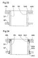
- Figs. 23 and 24 show modifications of the holder of an insert shown in Fig. 15 in the insert carrier.
- the insert EN is not supported on the base plate and forces acting upwards and downwards are produced exclusively by the engagement of the groove NE and the projection SAB via the covering parts ABL attached to the cover plate DP. ABR be intercepted.
- Such a holder can be provided in particular in applications where working with less jolting power.
- Fig. 24 an embodiment is shown in which between opposite surfaces of insert EN on the one hand and base plate, cover plate and cover plate on the other damping material, for example in the form of a lower damping profile DEG and / or an upper damping profile DEN is inserted.
- the damping material can, as outlined, be inserted between all contact or support surfaces, but can also be applied to one part These surfaces, for example, limited to vertical forces intercepting surfaces and / or surfaces for the use of down-pressing forces in the damping means DEG and upward lifting forces in the upper damping means DEN.
- the projections GAD in the lower edge region of the insert and / or SAD in the steps of the cover plate sections may be radially larger dimensions than in the example of FIG. 15.
- the damping profile DEN can, for. B. also be used as a single element in the example of FIG. 23.
- Fig. 25 shows a view of a cut-open insert carrier another advantageous stiffening of the insert carrier.
- a plate element PS is provided with a plurality of obliquely extending struts PSS, which engages the nodes PK converging struts with tabs PL in recesses PO of cover plate DP and base GP and is fixed there preferably by plug welding.
- the element PS which can be conveniently cut out of a flat plate, the advantage of material and weight savings.
- such a reinforcement is advantageous with one or more plate elements running in the longitudinal direction LR, but without being limited to only one or this direction.
- the shape of the plate element PS in one is accessible to a large variety of designs.
Landscapes
- Engineering & Computer Science (AREA)
- Manufacturing & Machinery (AREA)
- Chemical & Material Sciences (AREA)
- Ceramic Engineering (AREA)
- Mechanical Engineering (AREA)
- Connection Of Plates (AREA)
- Manufacturing Of Tubular Articles Or Embedded Moulded Articles (AREA)
- Press-Shaping Or Shaping Using Conveyers (AREA)
- Moulds, Cores, Or Mandrels (AREA)
- Panels For Use In Building Construction (AREA)
- Packaging For Recording Disks (AREA)
- Road Paving Structures (AREA)
- Rigid Containers With Two Or More Constituent Elements (AREA)
- Producing Shaped Articles From Materials (AREA)
- Artificial Fish Reefs (AREA)
Applications Claiming Priority (3)
| Application Number | Priority Date | Filing Date | Title |
|---|---|---|---|
| DE10254322A DE10254322A1 (de) | 2002-11-21 | 2002-11-21 | Anordnung zur Herstellung von Betonformsteinen |
| DE10254322 | 2002-11-21 | ||
| PCT/EP2003/011783 WO2004045817A1 (de) | 2002-11-21 | 2003-10-24 | Anordnung zur herstellung von betonformsteinen |
Publications (2)
| Publication Number | Publication Date |
|---|---|
| EP1565295A1 EP1565295A1 (de) | 2005-08-24 |
| EP1565295B1 true EP1565295B1 (de) | 2007-09-19 |
Family
ID=7715057
Family Applications (1)
| Application Number | Title | Priority Date | Filing Date |
|---|---|---|---|
| EP03811354A Expired - Lifetime EP1565295B1 (de) | 2002-11-21 | 2003-10-24 | Anordnung zur herstellung von betonformsteinen |
Country Status (8)
| Country | Link |
|---|---|
| US (1) | US20060081759A1 (da) |
| EP (1) | EP1565295B1 (da) |
| AT (1) | ATE373550T1 (da) |
| AU (1) | AU2003276164A1 (da) |
| CA (1) | CA2506859A1 (da) |
| DE (3) | DE10254322A1 (da) |
| DK (1) | DK1565295T3 (da) |
| WO (1) | WO2004045817A1 (da) |
Families Citing this family (5)
| Publication number | Priority date | Publication date | Assignee | Title |
|---|---|---|---|---|
| DE102004003896A1 (de) * | 2004-01-27 | 2005-08-11 | Kobra Formen Gmbh | Vorrichtung zur Herstellung von durch Rütteln verdichteten Formkörpern |
| CZ303347B6 (cs) * | 2007-06-11 | 2012-08-08 | Falta@Miloš | Pracovní podložka do vibrolisu a zpusob její výroby |
| CN108312322B (zh) * | 2018-02-11 | 2023-09-01 | 山东亮普建材科技有限公司 | 建筑模块生产设备 |
| CN110065147A (zh) * | 2019-06-03 | 2019-07-30 | 中交一公局海威工程建设有限公司 | 混凝土浇筑模具及混凝土浇筑方法 |
| CN114770698A (zh) * | 2022-03-30 | 2022-07-22 | 陆勇 | 一种具有防冻结构的混凝土试件加工用振实装置 |
Family Cites Families (36)
| Publication number | Priority date | Publication date | Assignee | Title |
|---|---|---|---|---|
| US257537A (en) * | 1882-05-09 | Febdeeiok van patten | ||
| US848697A (en) * | 1906-08-31 | 1907-04-02 | Manuel Silva | Concrete-block machine. |
| US1896372A (en) * | 1927-12-02 | 1933-02-07 | Richardson Co | Battery box mold |
| US2290910A (en) * | 1938-12-21 | 1942-07-28 | Champion Spark Plug Co | Semiautomatic press |
| US2308046A (en) * | 1939-12-23 | 1943-01-12 | Walter A Bishman | Apparatus for forming receptacles |
| US2413109A (en) * | 1941-04-11 | 1946-12-24 | Leipold Eugene | Apparatus for the manufacture of building blocks |
| US2529066A (en) * | 1946-06-17 | 1950-11-07 | Taft T Annas | Block molding machine |
| US2598254A (en) * | 1946-08-02 | 1952-05-27 | Jackson & Church Company | Machine for the manufacture of molded building units |
| US2532049A (en) * | 1948-08-11 | 1950-11-28 | Wittke Emil Paul | Mold for making hollow concrete blocks |
| US3095629A (en) * | 1959-11-17 | 1963-07-02 | Leonard D Long | Apparatus for making pre-cast cored building blocks |
| US3071834A (en) * | 1960-03-28 | 1963-01-08 | Fmc Corp | Molding apparatus |
| US3178791A (en) * | 1962-01-23 | 1965-04-20 | Babcock & Wilcox Co | Apparatus for molding refractory shapes |
| US3176372A (en) * | 1963-04-01 | 1965-04-06 | Thomas O Brown Jr | Machine for molding mastic articles |
| DE6601523U (de) * | 1964-08-06 | 1969-03-06 | Juergen H Kuesel | Formkasten zur herstellung von formsteinen aus formbaren material. |
| DE1264311B (de) * | 1964-08-06 | 1968-03-21 | Juergen H Kuesel | Formkasten zum Herstellen einer Vielzahl von in Reihen hinter- und nebeneinanderliegenden Steinen |
| DE1584523C3 (de) * | 1966-08-01 | 1973-10-11 | Juergen H. 2800 Bremen Kuesel | Formkasten zum Herstellen von Form steinen |
| US3674396A (en) * | 1970-09-21 | 1972-07-04 | Miles Lab | Biological specimen processing and embedding apparatus |
| DE2145746B2 (de) * | 1971-09-13 | 1975-11-13 | Manfred 7012 Schmiden Lebherz | Verfahren und Vorrichtung zur Herstellung eines Beton-Schalungssteines sowie Beton-Schalungsstein |
| US3932098A (en) * | 1974-12-18 | 1976-01-13 | Spartek Inc. | Case assembly with tungsten carbide inserts for ceramic tile die |
| US4005972A (en) * | 1975-04-04 | 1977-02-01 | Bearingwall Systems Inc. | Invertible apparatus for molding a concrete panel |
| US4238177A (en) * | 1978-04-24 | 1980-12-09 | Crile Eugene E | Molding machine with vibration isolation |
| US4218206A (en) * | 1978-10-02 | 1980-08-19 | Mullins Wayne L | Mold box apparatus |
| DE2934838A1 (de) * | 1979-08-29 | 1981-03-19 | Georges Rio de Janeiro Ruegner | Formkasten zur herstellung von betonsteinen |
| CA1154941A (en) * | 1980-06-13 | 1983-10-11 | Rodger Blackwood | Brick molding machine |
| US4351507A (en) * | 1981-01-16 | 1982-09-28 | Doublewal Corporation | Multi-part form with improved tie and stripping means |
| US4362497A (en) * | 1981-08-14 | 1982-12-07 | Igor Lifshitz | Food press form |
| US4941813A (en) * | 1988-12-13 | 1990-07-17 | Grubb Jr Lloyd T | Mold guidance system for block making machinery |
| US5248466A (en) * | 1992-01-31 | 1993-09-28 | Russell Iii William N | Method for making cast stone |
| DE19531800A1 (de) * | 1995-08-30 | 1997-03-06 | Kobra Formen & Anlagenbau Gmbh | Form zur Herstellung von Formsteinen |
| US5863792A (en) * | 1997-03-19 | 1999-01-26 | Becton Dickson And Company | Culture vessel assembly |
| JP2000127124A (ja) * | 1998-10-26 | 2000-05-09 | Shigeru Kobayashi | コンクリートブロック成形装置 |
| US6119804A (en) * | 1999-05-13 | 2000-09-19 | Owen; Thomas E. | Horizontally polarized shear-wave vibrator seismic source |
| US6758665B2 (en) * | 2000-12-07 | 2004-07-06 | Sigmund P. Cichos | Concrete block vibrator |
| DE10114398A1 (de) * | 2001-03-23 | 2002-09-26 | Kobra Formen Gmbh | Formrahmen für eine Form |
| DE10241238B4 (de) * | 2002-09-06 | 2007-09-27 | Kobra Formen Gmbh | Formeinsatz für Formmaschinen |
| DE602004007891T2 (de) * | 2003-02-11 | 2008-04-17 | Kvm Industrimaskiner A/S | Formeinrichtung mit kernen für betongiessmaschinen |
-
2002
- 2002-11-21 DE DE10254322A patent/DE10254322A1/de not_active Ceased
-
2003
- 2003-01-29 DE DE20301330U patent/DE20301330U1/de not_active Expired - Lifetime
- 2003-10-24 CA CA002506859A patent/CA2506859A1/en not_active Abandoned
- 2003-10-24 WO PCT/EP2003/011783 patent/WO2004045817A1/de not_active Ceased
- 2003-10-24 DE DE50308244T patent/DE50308244D1/de not_active Expired - Lifetime
- 2003-10-24 AT AT03811354T patent/ATE373550T1/de not_active IP Right Cessation
- 2003-10-24 AU AU2003276164A patent/AU2003276164A1/en not_active Abandoned
- 2003-10-24 EP EP03811354A patent/EP1565295B1/de not_active Expired - Lifetime
- 2003-10-24 US US10/535,759 patent/US20060081759A1/en not_active Abandoned
- 2003-10-24 DK DK03811354T patent/DK1565295T3/da active
Also Published As
| Publication number | Publication date |
|---|---|
| DK1565295T3 (da) | 2007-11-12 |
| AU2003276164A1 (en) | 2004-06-15 |
| DE20301330U1 (de) | 2003-04-30 |
| DE50308244D1 (de) | 2007-10-31 |
| US20060081759A1 (en) | 2006-04-20 |
| DE10254322A1 (de) | 2004-06-03 |
| CA2506859A1 (en) | 2004-06-03 |
| WO2004045817A1 (de) | 2004-06-03 |
| ATE373550T1 (de) | 2007-10-15 |
| EP1565295A1 (de) | 2005-08-24 |
Similar Documents
| Publication | Publication Date | Title |
|---|---|---|
| EP2643133B1 (de) | Form zur herstellung von betonformsteinen | |
| EP0730936B2 (de) | Rüttelform | |
| DE2900314A1 (de) | Verfahren und vorrichtung zum formen und zum mechanischen oder halbmechanischen setzen von pflastersteinen oder modulierten fliesen aus beton oder anderen werkstoffen | |
| WO2009147016A1 (de) | Form zur herstellung von betonformsteinen | |
| EP1565295A1 (de) | Anordnung zur herstellung von betonformsteinen | |
| EP3000571B1 (de) | Vorrichtung zur herstellung von betonformteilen | |
| EP1967340A2 (de) | Form zur Herstellung von Betonformkörpern | |
| DE2832295B2 (de) | Formtisch für Betonfertigplatten | |
| EP4137284B1 (de) | Formgebungssystem | |
| EP2501534A1 (de) | FORMVORRICHTUNG FÜR EINE SPRITZGIEßMASCHINE UND VERFAHREN ZUR HERSTELLUNG EINES GEGENSTANDES AUS EINEM ELASTOMEREN MATERIAL | |
| DE102018121564A1 (de) | Vorrichtung zum Herstellen von Steinformlingen für Mauerwerksteine, insbesondere Kalksandsteine, mit verstellbaren Formwänden | |
| WO2004065089A1 (de) | Auflastvorrichtung | |
| AT524345B1 (de) | Halb-Mauerstein und Verfahren zum Produzieren eines Halb-Mauersteins | |
| DE102006059205B4 (de) | Pflasterstein mit Natursteinoptik sowie Vorrichtung zu deren Herstellung | |
| DE102010016444A1 (de) | Form zur maschinellen Herstellung von Betonformsteinen | |
| WO2007101869A2 (de) | Vorrichtung zur herstellung von betonformkörpern | |
| WO2006005091A1 (de) | Vorrichtung zum herstellen eines hohlbausteins aus einer hydraulisch aushärtenden, feuchten bausteinmasse | |
| DE3920095C2 (da) | ||
| DE102006026115A1 (de) | Anordnung zur Herstellung von Betonformsteinen, Form für eine solche Anordnung und Verfahren zur Herstellung einer solchen Form | |
| DE20115860U1 (de) | Preßvorrichtung | |
| DE202006019944U1 (de) | Vorrichtung zur Herstellung von Betonformkörpern | |
| EP1870217A2 (de) | Verfahren sowie Form zum Herstellen von Bodenplatten aus zementgebundenem Material bzw. Beton | |
| DE69715524T2 (de) | Verfahren zur Herstellung eines Betonmastes, Vorrichtung zur Durchführung des Verfahrens und damit hergestellter Mast | |
| EP1874514B1 (de) | Vorrichtung zur herstellung von betonformsteinen | |
| EP2154414A1 (de) | Verfahren und Vorrichtung zur Befestigung eines Bauteils |
Legal Events
| Date | Code | Title | Description |
|---|---|---|---|
| PUAI | Public reference made under article 153(3) epc to a published international application that has entered the european phase |
Free format text: ORIGINAL CODE: 0009012 |
|
| 17P | Request for examination filed |
Effective date: 20050621 |
|
| AK | Designated contracting states |
Kind code of ref document: A1 Designated state(s): AT BE BG CH CY CZ DE DK EE ES FI FR GB GR HU IE IT LI LU MC NL PT RO SE SI SK TR |
|
| AX | Request for extension of the european patent |
Extension state: AL LT LV MK |
|
| DAX | Request for extension of the european patent (deleted) | ||
| GRAP | Despatch of communication of intention to grant a patent |
Free format text: ORIGINAL CODE: EPIDOSNIGR1 |
|
| RAP1 | Party data changed (applicant data changed or rights of an application transferred) |
Owner name: KOBRA FORMEN GMBH |
|
| GRAS | Grant fee paid |
Free format text: ORIGINAL CODE: EPIDOSNIGR3 |
|
| GRAA | (expected) grant |
Free format text: ORIGINAL CODE: 0009210 |
|
| AK | Designated contracting states |
Kind code of ref document: B1 Designated state(s): AT BE BG CH CY CZ DE DK EE ES FI FR GB GR HU IE IT LI LU MC NL PT RO SE SI SK TR |
|
| REG | Reference to a national code |
Ref country code: GB Ref legal event code: FG4D Free format text: NOT ENGLISH |
|
| REG | Reference to a national code |
Ref country code: CH Ref legal event code: EP |
|
| REF | Corresponds to: |
Ref document number: 50308244 Country of ref document: DE Date of ref document: 20071031 Kind code of ref document: P |
|
| REG | Reference to a national code |
Ref country code: DK Ref legal event code: T3 |
|
| REG | Reference to a national code |
Ref country code: IE Ref legal event code: FG4D Free format text: LANGUAGE OF EP DOCUMENT: GERMAN |
|
| REG | Reference to a national code |
Ref country code: CH Ref legal event code: NV Representative=s name: RIEDERER HASLER & PARTNER PATENTANWAELTE AG |
|
| PG25 | Lapsed in a contracting state [announced via postgrant information from national office to epo] |
Ref country code: FI Free format text: LAPSE BECAUSE OF FAILURE TO SUBMIT A TRANSLATION OF THE DESCRIPTION OR TO PAY THE FEE WITHIN THE PRESCRIBED TIME-LIMIT Effective date: 20070919 |
|
| REG | Reference to a national code |
Ref country code: HU Ref legal event code: AG4A Ref document number: E002466 Country of ref document: HU |
|
| PG25 | Lapsed in a contracting state [announced via postgrant information from national office to epo] |
Ref country code: ES Free format text: LAPSE BECAUSE OF FAILURE TO SUBMIT A TRANSLATION OF THE DESCRIPTION OR TO PAY THE FEE WITHIN THE PRESCRIBED TIME-LIMIT Effective date: 20071230 Ref country code: GR Free format text: LAPSE BECAUSE OF FAILURE TO SUBMIT A TRANSLATION OF THE DESCRIPTION OR TO PAY THE FEE WITHIN THE PRESCRIBED TIME-LIMIT Effective date: 20071220 |
|
| REG | Reference to a national code |
Ref country code: IE Ref legal event code: FD4D |
|
| EN | Fr: translation not filed | ||
| PG25 | Lapsed in a contracting state [announced via postgrant information from national office to epo] |
Ref country code: PT Free format text: LAPSE BECAUSE OF FAILURE TO SUBMIT A TRANSLATION OF THE DESCRIPTION OR TO PAY THE FEE WITHIN THE PRESCRIBED TIME-LIMIT Effective date: 20080219 Ref country code: GB Free format text: LAPSE BECAUSE OF FAILURE TO SUBMIT A TRANSLATION OF THE DESCRIPTION OR TO PAY THE FEE WITHIN THE PRESCRIBED TIME-LIMIT Effective date: 20070919 Ref country code: MC Free format text: LAPSE BECAUSE OF NON-PAYMENT OF DUE FEES Effective date: 20071031 Ref country code: SK Free format text: LAPSE BECAUSE OF FAILURE TO SUBMIT A TRANSLATION OF THE DESCRIPTION OR TO PAY THE FEE WITHIN THE PRESCRIBED TIME-LIMIT Effective date: 20070919 |
|
| PG25 | Lapsed in a contracting state [announced via postgrant information from national office to epo] |
Ref country code: RO Free format text: LAPSE BECAUSE OF FAILURE TO SUBMIT A TRANSLATION OF THE DESCRIPTION OR TO PAY THE FEE WITHIN THE PRESCRIBED TIME-LIMIT Effective date: 20070919 Ref country code: SE Free format text: LAPSE BECAUSE OF FAILURE TO SUBMIT A TRANSLATION OF THE DESCRIPTION OR TO PAY THE FEE WITHIN THE PRESCRIBED TIME-LIMIT Effective date: 20071219 |
|
| PLBE | No opposition filed within time limit |
Free format text: ORIGINAL CODE: 0009261 |
|
| STAA | Information on the status of an ep patent application or granted ep patent |
Free format text: STATUS: NO OPPOSITION FILED WITHIN TIME LIMIT |
|
| 26N | No opposition filed |
Effective date: 20080620 |
|
| PG25 | Lapsed in a contracting state [announced via postgrant information from national office to epo] |
Ref country code: FR Free format text: LAPSE BECAUSE OF FAILURE TO SUBMIT A TRANSLATION OF THE DESCRIPTION OR TO PAY THE FEE WITHIN THE PRESCRIBED TIME-LIMIT Effective date: 20080523 |
|
| PG25 | Lapsed in a contracting state [announced via postgrant information from national office to epo] |
Ref country code: IE Free format text: LAPSE BECAUSE OF FAILURE TO SUBMIT A TRANSLATION OF THE DESCRIPTION OR TO PAY THE FEE WITHIN THE PRESCRIBED TIME-LIMIT Effective date: 20070919 |
|
| PGFP | Annual fee paid to national office [announced via postgrant information from national office to epo] |
Ref country code: NL Payment date: 20081023 Year of fee payment: 6 |
|
| PG25 | Lapsed in a contracting state [announced via postgrant information from national office to epo] |
Ref country code: EE Free format text: LAPSE BECAUSE OF FAILURE TO SUBMIT A TRANSLATION OF THE DESCRIPTION OR TO PAY THE FEE WITHIN THE PRESCRIBED TIME-LIMIT Effective date: 20070919 |
|
| PGFP | Annual fee paid to national office [announced via postgrant information from national office to epo] |
Ref country code: CH Payment date: 20081027 Year of fee payment: 6 Ref country code: CZ Payment date: 20081020 Year of fee payment: 6 Ref country code: DK Payment date: 20081024 Year of fee payment: 6 |
|
| PGFP | Annual fee paid to national office [announced via postgrant information from national office to epo] |
Ref country code: AT Payment date: 20081023 Year of fee payment: 6 |
|
| PGFP | Annual fee paid to national office [announced via postgrant information from national office to epo] |
Ref country code: BE Payment date: 20081024 Year of fee payment: 6 Ref country code: IT Payment date: 20081025 Year of fee payment: 6 |
|
| PG25 | Lapsed in a contracting state [announced via postgrant information from national office to epo] |
Ref country code: SI Free format text: LAPSE BECAUSE OF FAILURE TO SUBMIT A TRANSLATION OF THE DESCRIPTION OR TO PAY THE FEE WITHIN THE PRESCRIBED TIME-LIMIT Effective date: 20070919 |
|
| PG25 | Lapsed in a contracting state [announced via postgrant information from national office to epo] |
Ref country code: CY Free format text: LAPSE BECAUSE OF FAILURE TO SUBMIT A TRANSLATION OF THE DESCRIPTION OR TO PAY THE FEE WITHIN THE PRESCRIBED TIME-LIMIT Effective date: 20070919 |
|
| PG25 | Lapsed in a contracting state [announced via postgrant information from national office to epo] |
Ref country code: LU Free format text: LAPSE BECAUSE OF NON-PAYMENT OF DUE FEES Effective date: 20071024 Ref country code: BG Free format text: LAPSE BECAUSE OF FAILURE TO SUBMIT A TRANSLATION OF THE DESCRIPTION OR TO PAY THE FEE WITHIN THE PRESCRIBED TIME-LIMIT Effective date: 20071219 |
|
| PG25 | Lapsed in a contracting state [announced via postgrant information from national office to epo] |
Ref country code: TR Free format text: LAPSE BECAUSE OF FAILURE TO SUBMIT A TRANSLATION OF THE DESCRIPTION OR TO PAY THE FEE WITHIN THE PRESCRIBED TIME-LIMIT Effective date: 20070919 |
|
| PGFP | Annual fee paid to national office [announced via postgrant information from national office to epo] |
Ref country code: HU Payment date: 20081022 Year of fee payment: 6 |
|
| BERE | Be: lapsed |
Owner name: KOBRA FORMEN G.M.B.H. Effective date: 20091031 |
|
| REG | Reference to a national code |
Ref country code: NL Ref legal event code: V1 Effective date: 20100501 |
|
| REG | Reference to a national code |
Ref country code: CH Ref legal event code: PL |
|
| REG | Reference to a national code |
Ref country code: DK Ref legal event code: EBP |
|
| PG25 | Lapsed in a contracting state [announced via postgrant information from national office to epo] |
Ref country code: NL Free format text: LAPSE BECAUSE OF NON-PAYMENT OF DUE FEES Effective date: 20100501 Ref country code: HU Free format text: LAPSE BECAUSE OF NON-PAYMENT OF DUE FEES Effective date: 20091025 |
|
| PG25 | Lapsed in a contracting state [announced via postgrant information from national office to epo] |
Ref country code: CZ Free format text: LAPSE BECAUSE OF NON-PAYMENT OF DUE FEES Effective date: 20091024 Ref country code: AT Free format text: LAPSE BECAUSE OF NON-PAYMENT OF DUE FEES Effective date: 20091024 |
|
| PG25 | Lapsed in a contracting state [announced via postgrant information from national office to epo] |
Ref country code: LI Free format text: LAPSE BECAUSE OF NON-PAYMENT OF DUE FEES Effective date: 20091031 Ref country code: BE Free format text: LAPSE BECAUSE OF NON-PAYMENT OF DUE FEES Effective date: 20091031 Ref country code: CH Free format text: LAPSE BECAUSE OF NON-PAYMENT OF DUE FEES Effective date: 20091031 |
|
| PG25 | Lapsed in a contracting state [announced via postgrant information from national office to epo] |
Ref country code: DK Free format text: LAPSE BECAUSE OF NON-PAYMENT OF DUE FEES Effective date: 20091031 |
|
| PG25 | Lapsed in a contracting state [announced via postgrant information from national office to epo] |
Ref country code: IT Free format text: LAPSE BECAUSE OF NON-PAYMENT OF DUE FEES Effective date: 20091024 |
|
| REG | Reference to a national code |
Ref country code: DE Ref legal event code: R082 Ref document number: 50308244 Country of ref document: DE Representative=s name: BAUR & WEBER PATENTANWAELTE, DE Ref country code: DE Ref legal event code: R082 Ref document number: 50308244 Country of ref document: DE Representative=s name: BAUR & WEBER PATENTANWAELTE PARTG MBB, DE |
|
| PGFP | Annual fee paid to national office [announced via postgrant information from national office to epo] |
Ref country code: DE Payment date: 20181031 Year of fee payment: 16 |
|
| REG | Reference to a national code |
Ref country code: DE Ref legal event code: R119 Ref document number: 50308244 Country of ref document: DE |
|
| PG25 | Lapsed in a contracting state [announced via postgrant information from national office to epo] |
Ref country code: DE Free format text: LAPSE BECAUSE OF NON-PAYMENT OF DUE FEES Effective date: 20200501 |