EP1565658B1 - Systeme hydraulique a deux circuits - Google Patents
Systeme hydraulique a deux circuits Download PDFInfo
- Publication number
- EP1565658B1 EP1565658B1 EP03782096A EP03782096A EP1565658B1 EP 1565658 B1 EP1565658 B1 EP 1565658B1 EP 03782096 A EP03782096 A EP 03782096A EP 03782096 A EP03782096 A EP 03782096A EP 1565658 B1 EP1565658 B1 EP 1565658B1
- Authority
- EP
- European Patent Office
- Prior art keywords
- valve
- pressure
- control
- summing
- consumer
- Prior art date
- Legal status (The legal status is an assumption and is not a legal conclusion. Google has not performed a legal analysis and makes no representation as to the accuracy of the status listed.)
- Expired - Lifetime
Links
- 230000009977 dual effect Effects 0.000 title claims 11
- 238000006073 displacement reaction Methods 0.000 claims description 9
- 238000011144 upstream manufacturing Methods 0.000 claims description 7
- 230000001186 cumulative effect Effects 0.000 description 8
- 230000011664 signaling Effects 0.000 description 8
- 238000010586 diagram Methods 0.000 description 3
- 230000000712 assembly Effects 0.000 description 2
- 238000000429 assembly Methods 0.000 description 2
- 230000000694 effects Effects 0.000 description 2
- 230000010363 phase shift Effects 0.000 description 2
- 230000036316 preload Effects 0.000 description 2
- 241001261858 Alsodes Species 0.000 description 1
- 230000001133 acceleration Effects 0.000 description 1
- 230000000903 blocking effect Effects 0.000 description 1
- 230000001419 dependent effect Effects 0.000 description 1
- 238000001514 detection method Methods 0.000 description 1
- 238000011161 development Methods 0.000 description 1
- 230000018109 developmental process Effects 0.000 description 1
- 230000002028 premature Effects 0.000 description 1
- 238000010079 rubber tapping Methods 0.000 description 1
- 238000005303 weighing Methods 0.000 description 1
Images



Classifications
-
- F—MECHANICAL ENGINEERING; LIGHTING; HEATING; WEAPONS; BLASTING
- F15—FLUID-PRESSURE ACTUATORS; HYDRAULICS OR PNEUMATICS IN GENERAL
- F15B—SYSTEMS ACTING BY MEANS OF FLUIDS IN GENERAL; FLUID-PRESSURE ACTUATORS, e.g. SERVOMOTORS; DETAILS OF FLUID-PRESSURE SYSTEMS, NOT OTHERWISE PROVIDED FOR
- F15B11/00—Servomotor systems without provision for follow-up action; Circuits therefor
- F15B11/02—Systems essentially incorporating special features for controlling the speed or actuating force of an output member
-
- F—MECHANICAL ENGINEERING; LIGHTING; HEATING; WEAPONS; BLASTING
- F15—FLUID-PRESSURE ACTUATORS; HYDRAULICS OR PNEUMATICS IN GENERAL
- F15B—SYSTEMS ACTING BY MEANS OF FLUIDS IN GENERAL; FLUID-PRESSURE ACTUATORS, e.g. SERVOMOTORS; DETAILS OF FLUID-PRESSURE SYSTEMS, NOT OTHERWISE PROVIDED FOR
- F15B11/00—Servomotor systems without provision for follow-up action; Circuits therefor
- F15B11/16—Servomotor systems without provision for follow-up action; Circuits therefor with two or more servomotors
- F15B11/161—Servomotor systems without provision for follow-up action; Circuits therefor with two or more servomotors with sensing of servomotor demand or load
- F15B11/163—Servomotor systems without provision for follow-up action; Circuits therefor with two or more servomotors with sensing of servomotor demand or load for sharing the pump output equally amongst users or groups of users, e.g. using anti-saturation, pressure compensation
-
- E—FIXED CONSTRUCTIONS
- E02—HYDRAULIC ENGINEERING; FOUNDATIONS; SOIL SHIFTING
- E02F—DREDGING; SOIL-SHIFTING
- E02F9/00—Component parts of dredgers or soil-shifting machines, not restricted to one of the kinds covered by groups E02F3/00 - E02F7/00
- E02F9/20—Drives; Control devices
- E02F9/22—Hydraulic or pneumatic drives
- E02F9/2221—Control of flow rate; Load sensing arrangements
- E02F9/2239—Control of flow rate; Load sensing arrangements using two or more pumps with cross-assistance
-
- E—FIXED CONSTRUCTIONS
- E02—HYDRAULIC ENGINEERING; FOUNDATIONS; SOIL SHIFTING
- E02F—DREDGING; SOIL-SHIFTING
- E02F9/00—Component parts of dredgers or soil-shifting machines, not restricted to one of the kinds covered by groups E02F3/00 - E02F7/00
- E02F9/20—Drives; Control devices
- E02F9/22—Hydraulic or pneumatic drives
- E02F9/2278—Hydraulic circuits
- E02F9/2292—Systems with two or more pumps
-
- E—FIXED CONSTRUCTIONS
- E02—HYDRAULIC ENGINEERING; FOUNDATIONS; SOIL SHIFTING
- E02F—DREDGING; SOIL-SHIFTING
- E02F9/00—Component parts of dredgers or soil-shifting machines, not restricted to one of the kinds covered by groups E02F3/00 - E02F7/00
- E02F9/20—Drives; Control devices
- E02F9/22—Hydraulic or pneumatic drives
- E02F9/2278—Hydraulic circuits
- E02F9/2296—Systems with a variable displacement pump
-
- F—MECHANICAL ENGINEERING; LIGHTING; HEATING; WEAPONS; BLASTING
- F15—FLUID-PRESSURE ACTUATORS; HYDRAULICS OR PNEUMATICS IN GENERAL
- F15B—SYSTEMS ACTING BY MEANS OF FLUIDS IN GENERAL; FLUID-PRESSURE ACTUATORS, e.g. SERVOMOTORS; DETAILS OF FLUID-PRESSURE SYSTEMS, NOT OTHERWISE PROVIDED FOR
- F15B11/00—Servomotor systems without provision for follow-up action; Circuits therefor
- F15B11/16—Servomotor systems without provision for follow-up action; Circuits therefor with two or more servomotors
- F15B11/161—Servomotor systems without provision for follow-up action; Circuits therefor with two or more servomotors with sensing of servomotor demand or load
- F15B11/165—Servomotor systems without provision for follow-up action; Circuits therefor with two or more servomotors with sensing of servomotor demand or load for adjusting the pump output or bypass in response to demand
-
- F—MECHANICAL ENGINEERING; LIGHTING; HEATING; WEAPONS; BLASTING
- F15—FLUID-PRESSURE ACTUATORS; HYDRAULICS OR PNEUMATICS IN GENERAL
- F15B—SYSTEMS ACTING BY MEANS OF FLUIDS IN GENERAL; FLUID-PRESSURE ACTUATORS, e.g. SERVOMOTORS; DETAILS OF FLUID-PRESSURE SYSTEMS, NOT OTHERWISE PROVIDED FOR
- F15B11/00—Servomotor systems without provision for follow-up action; Circuits therefor
- F15B11/16—Servomotor systems without provision for follow-up action; Circuits therefor with two or more servomotors
- F15B11/17—Servomotor systems without provision for follow-up action; Circuits therefor with two or more servomotors using two or more pumps
-
- F—MECHANICAL ENGINEERING; LIGHTING; HEATING; WEAPONS; BLASTING
- F15—FLUID-PRESSURE ACTUATORS; HYDRAULICS OR PNEUMATICS IN GENERAL
- F15B—SYSTEMS ACTING BY MEANS OF FLUIDS IN GENERAL; FLUID-PRESSURE ACTUATORS, e.g. SERVOMOTORS; DETAILS OF FLUID-PRESSURE SYSTEMS, NOT OTHERWISE PROVIDED FOR
- F15B2211/00—Circuits for servomotor systems
- F15B2211/20—Fluid pressure source, e.g. accumulator or variable axial piston pump
- F15B2211/205—Systems with pumps
- F15B2211/2053—Type of pump
- F15B2211/20546—Type of pump variable capacity
-
- F—MECHANICAL ENGINEERING; LIGHTING; HEATING; WEAPONS; BLASTING
- F15—FLUID-PRESSURE ACTUATORS; HYDRAULICS OR PNEUMATICS IN GENERAL
- F15B—SYSTEMS ACTING BY MEANS OF FLUIDS IN GENERAL; FLUID-PRESSURE ACTUATORS, e.g. SERVOMOTORS; DETAILS OF FLUID-PRESSURE SYSTEMS, NOT OTHERWISE PROVIDED FOR
- F15B2211/00—Circuits for servomotor systems
- F15B2211/20—Fluid pressure source, e.g. accumulator or variable axial piston pump
- F15B2211/205—Systems with pumps
- F15B2211/20576—Systems with pumps with multiple pumps
-
- F—MECHANICAL ENGINEERING; LIGHTING; HEATING; WEAPONS; BLASTING
- F15—FLUID-PRESSURE ACTUATORS; HYDRAULICS OR PNEUMATICS IN GENERAL
- F15B—SYSTEMS ACTING BY MEANS OF FLUIDS IN GENERAL; FLUID-PRESSURE ACTUATORS, e.g. SERVOMOTORS; DETAILS OF FLUID-PRESSURE SYSTEMS, NOT OTHERWISE PROVIDED FOR
- F15B2211/00—Circuits for servomotor systems
- F15B2211/30—Directional control
- F15B2211/305—Directional control characterised by the type of valves
- F15B2211/30505—Non-return valves, i.e. check valves
-
- F—MECHANICAL ENGINEERING; LIGHTING; HEATING; WEAPONS; BLASTING
- F15—FLUID-PRESSURE ACTUATORS; HYDRAULICS OR PNEUMATICS IN GENERAL
- F15B—SYSTEMS ACTING BY MEANS OF FLUIDS IN GENERAL; FLUID-PRESSURE ACTUATORS, e.g. SERVOMOTORS; DETAILS OF FLUID-PRESSURE SYSTEMS, NOT OTHERWISE PROVIDED FOR
- F15B2211/00—Circuits for servomotor systems
- F15B2211/30—Directional control
- F15B2211/305—Directional control characterised by the type of valves
- F15B2211/30525—Directional control valves, e.g. 4/3-directional control valve
- F15B2211/3053—In combination with a pressure compensating valve
- F15B2211/30555—Inlet and outlet of the pressure compensating valve being connected to the directional control valve
-
- F—MECHANICAL ENGINEERING; LIGHTING; HEATING; WEAPONS; BLASTING
- F15—FLUID-PRESSURE ACTUATORS; HYDRAULICS OR PNEUMATICS IN GENERAL
- F15B—SYSTEMS ACTING BY MEANS OF FLUIDS IN GENERAL; FLUID-PRESSURE ACTUATORS, e.g. SERVOMOTORS; DETAILS OF FLUID-PRESSURE SYSTEMS, NOT OTHERWISE PROVIDED FOR
- F15B2211/00—Circuits for servomotor systems
- F15B2211/30—Directional control
- F15B2211/31—Directional control characterised by the positions of the valve element
- F15B2211/3105—Neutral or centre positions
- F15B2211/3111—Neutral or centre positions the pump port being closed in the centre position, e.g. so-called closed centre
-
- F—MECHANICAL ENGINEERING; LIGHTING; HEATING; WEAPONS; BLASTING
- F15—FLUID-PRESSURE ACTUATORS; HYDRAULICS OR PNEUMATICS IN GENERAL
- F15B—SYSTEMS ACTING BY MEANS OF FLUIDS IN GENERAL; FLUID-PRESSURE ACTUATORS, e.g. SERVOMOTORS; DETAILS OF FLUID-PRESSURE SYSTEMS, NOT OTHERWISE PROVIDED FOR
- F15B2211/00—Circuits for servomotor systems
- F15B2211/30—Directional control
- F15B2211/31—Directional control characterised by the positions of the valve element
- F15B2211/3144—Directional control characterised by the positions of the valve element the positions being continuously variable, e.g. as realised by proportional valves
-
- F—MECHANICAL ENGINEERING; LIGHTING; HEATING; WEAPONS; BLASTING
- F15—FLUID-PRESSURE ACTUATORS; HYDRAULICS OR PNEUMATICS IN GENERAL
- F15B—SYSTEMS ACTING BY MEANS OF FLUIDS IN GENERAL; FLUID-PRESSURE ACTUATORS, e.g. SERVOMOTORS; DETAILS OF FLUID-PRESSURE SYSTEMS, NOT OTHERWISE PROVIDED FOR
- F15B2211/00—Circuits for servomotor systems
- F15B2211/30—Directional control
- F15B2211/315—Directional control characterised by the connections of the valve or valves in the circuit
- F15B2211/3157—Directional control characterised by the connections of the valve or valves in the circuit being connected to a pressure source, an output member and a return line
- F15B2211/31576—Directional control characterised by the connections of the valve or valves in the circuit being connected to a pressure source, an output member and a return line having a single pressure source and a single output member
-
- F—MECHANICAL ENGINEERING; LIGHTING; HEATING; WEAPONS; BLASTING
- F15—FLUID-PRESSURE ACTUATORS; HYDRAULICS OR PNEUMATICS IN GENERAL
- F15B—SYSTEMS ACTING BY MEANS OF FLUIDS IN GENERAL; FLUID-PRESSURE ACTUATORS, e.g. SERVOMOTORS; DETAILS OF FLUID-PRESSURE SYSTEMS, NOT OTHERWISE PROVIDED FOR
- F15B2211/00—Circuits for servomotor systems
- F15B2211/30—Directional control
- F15B2211/315—Directional control characterised by the connections of the valve or valves in the circuit
- F15B2211/3157—Directional control characterised by the connections of the valve or valves in the circuit being connected to a pressure source, an output member and a return line
- F15B2211/31582—Directional control characterised by the connections of the valve or valves in the circuit being connected to a pressure source, an output member and a return line having multiple pressure sources and a single output member
-
- F—MECHANICAL ENGINEERING; LIGHTING; HEATING; WEAPONS; BLASTING
- F15—FLUID-PRESSURE ACTUATORS; HYDRAULICS OR PNEUMATICS IN GENERAL
- F15B—SYSTEMS ACTING BY MEANS OF FLUIDS IN GENERAL; FLUID-PRESSURE ACTUATORS, e.g. SERVOMOTORS; DETAILS OF FLUID-PRESSURE SYSTEMS, NOT OTHERWISE PROVIDED FOR
- F15B2211/00—Circuits for servomotor systems
- F15B2211/30—Directional control
- F15B2211/32—Directional control characterised by the type of actuation
- F15B2211/329—Directional control characterised by the type of actuation actuated by fluid pressure
-
- F—MECHANICAL ENGINEERING; LIGHTING; HEATING; WEAPONS; BLASTING
- F15—FLUID-PRESSURE ACTUATORS; HYDRAULICS OR PNEUMATICS IN GENERAL
- F15B—SYSTEMS ACTING BY MEANS OF FLUIDS IN GENERAL; FLUID-PRESSURE ACTUATORS, e.g. SERVOMOTORS; DETAILS OF FLUID-PRESSURE SYSTEMS, NOT OTHERWISE PROVIDED FOR
- F15B2211/00—Circuits for servomotor systems
- F15B2211/40—Flow control
- F15B2211/405—Flow control characterised by the type of flow control means or valve
- F15B2211/40515—Flow control characterised by the type of flow control means or valve with variable throttles or orifices
-
- F—MECHANICAL ENGINEERING; LIGHTING; HEATING; WEAPONS; BLASTING
- F15—FLUID-PRESSURE ACTUATORS; HYDRAULICS OR PNEUMATICS IN GENERAL
- F15B—SYSTEMS ACTING BY MEANS OF FLUIDS IN GENERAL; FLUID-PRESSURE ACTUATORS, e.g. SERVOMOTORS; DETAILS OF FLUID-PRESSURE SYSTEMS, NOT OTHERWISE PROVIDED FOR
- F15B2211/00—Circuits for servomotor systems
- F15B2211/60—Circuit components or control therefor
- F15B2211/605—Load sensing circuits
- F15B2211/6051—Load sensing circuits having valve means between output member and the load sensing circuit
- F15B2211/6052—Load sensing circuits having valve means between output member and the load sensing circuit using check valves
-
- F—MECHANICAL ENGINEERING; LIGHTING; HEATING; WEAPONS; BLASTING
- F15—FLUID-PRESSURE ACTUATORS; HYDRAULICS OR PNEUMATICS IN GENERAL
- F15B—SYSTEMS ACTING BY MEANS OF FLUIDS IN GENERAL; FLUID-PRESSURE ACTUATORS, e.g. SERVOMOTORS; DETAILS OF FLUID-PRESSURE SYSTEMS, NOT OTHERWISE PROVIDED FOR
- F15B2211/00—Circuits for servomotor systems
- F15B2211/60—Circuit components or control therefor
- F15B2211/605—Load sensing circuits
- F15B2211/6051—Load sensing circuits having valve means between output member and the load sensing circuit
- F15B2211/6057—Load sensing circuits having valve means between output member and the load sensing circuit using directional control valves
Definitions
- the invention relates to a hydraulic two-circuit system for controlling consumers of a mobile device, in particular a tracked device according to the preamble of patent claims 1.
- a disadvantage is further that is switched very early in the known solutions to a single-circuit system, since the Summierventilan instrument the circles already summed when more pressure medium is requested, as can be supplied by the pump.
- the present invention seeks to provide a two-circuit system in which the required for a load pressure independent control of the consumers to be summed measuring orifices are optimally adapted to the two-circuit mode, and in which premature summation can be prevented.
- the summation of the pressure medium flows takes place only after the orifice plate of the main axis associated with the consumer and the pressure compensator, so that this only has to be adapted to the pump quantity of the associated circuit. Since the summation thus takes place only after the metering orifice of the summed consumer, all metering orifices of the summed main axes can be matched to the pump quantity of the respective pump. By this measure, the controllability is greatly improved because in the superposition of multiple consumers, the degree of subsaturation ( ⁇ p) between pump pressure and load pressure does not drop too much.
- the summing valve arrangement has a summing proportional valve, which forms a summing orifice, which is followed by a summing pressure balance.
- the control of this summing proportional valve can be done electrically, mechanically or hydraulically.
- the Summierventilan instrument a LS-reporting valve, via which the summation of the respective LS signal is passed to the LUDV pressure compensator of the summation. If, in this case, the highest load pressure in the quantity-receiving circuit is lower than in the quantity-delivering circuit, then the pump pressure in the receiving circuit is not raised. Conversely, when the receiving circuit has a higher load pressure than the donor circuit, the pump pressure is increased in the amount-donating circuit.
- the early switching over to a single circuit can be further prevented by the control signal actuating the summing valve arrangement being selected such that it does not summate until the consumer in the two-circuit system has already been activated, for example accelerated, via its consumer valve axis.
- a proportional directional control valve with a metering orifice and a directional part is used in the main axis associated with each consumer, wherein the metering orifice is followed by a LUDV pressure compensator.
- the control pressure in response to the operation of a donor device, such as a pilot control device to the summation proportional valve can be applied.
- the Summierventilanordung may further be assigned to a control valve, via which the pump pressure leading and the load pressure leading lines are connected to each other.
- the control of this control valve for example, via a control pressure, which is delivered on the basis of a predetermined by the operator manual control signal. That is, by means of this control valve, the two-circuit system can be switched independently of a subsaturation in the circles in a single-circuit system. This may be necessary, for example, when the crawler undercarriage is driven in superposition with other consumers.
- control valve and the LS signaling valve can also be integrated in the totalizing proportional valve. In a preferred variant, this is carried out with an additional switching position in which the two lines leading the pump pressure of the two circuits are connected to each other.
- This can be achieved, for example, by designing the control spring arrangement biasing a valve spool of the totalizing proportional valve into its basic position (blocking position) in such a way that the control spring preload can be reduced on one side and the valve spool is then displaced into said switching position due to the unilaterally reduced forces.
- a control spring of the summation proportional valve can be hydraulically biased by means of a control pressure, wherein a control pressure leading control line by means of an override valve with the tank is connected, so that this control pressure is lowered and correspondingly reduces the bias of the control spring.
- nozzles may be connected upstream of the summation points of consumers usually having low load pressure, so that the desired distribution of the quantity supplied between low-pressure and high-pressure consumers may be obtained for the quantity supplied from the other circuit.
- the pressure medium flow from the connected circuit opens into a line section between a load-holding valve of the consumer valve axis and a directional part of the proportional valve.
- FIG. 1 shows a basic scheme of an excavator control, which is constructed as a two-circuit system with two hydraulic circuits 2, 4. About the two circles can be 8, 10 of the excavator, such as the drives of a chassis with two tracks or the equipment of the excavator, such as a slewing gear, a handle, a spoon or a boom control.
- the pressure medium supply of the two circuits 2, 4 takes place in each case via a variable displacement pump 6, 7, which are preferably controlled as a function of the maximum load pressure in the respective circuit.
- a summing valve arrangement 12 is provided, via which a presettable amount of pressure medium can be supplied by the variable displacement pump 7 to the consumer 8.
- a summing line 24 branches off, leading to the summing valve arrangement 12.
- This has a summation orifice 26, which is followed by a LUDV Summier horrwaage 28.
- This is like the pressure compensators 16 of the consumer valve axes in the opening direction acted upon by the pressure downstream of the metering orifice 26 and in the closing direction with the load pressure applied in the circuit 4.
- This load pressure is reported in the present case via the LS line 18 to the pressure compensator 28.
- the pressure compensator 28 is a load-holding valve 21 connected downstream.
- the summing line 24 opens downstream of the pressure compensator 16, the load-holding valve 21 and the load valve axis associated with the consumer 8 in the leading to the consumer 8 working line 30 a. That is, the summation takes place only after the metering orifice 14, the pressure compensator 16 and the load-holding valve 21, so that their cross-sections are adapted only to the maximum, supplied by the pump 6 pressure medium volume flow.
- the summing valve arrangement 12 also has an LS signaling valve 32.
- the LS signaling valve 32 blocks the connection the LS line 18 to the pressure compensator 28 from.
- the LS line 18 is connected to the pressure compensator 28.
- the switching of the LS signaling valve 32 can be done, for example, in dependence on the control of the variable orifice 14.
- pressure medium is fed from the circuit 4 into the circuit 2.
- the LS-reporting valve 32 can be omitted and the one control side of the pressure compensator 28 can be permanently connected to the LS line 18.
- a summation in the opposite direction so that pressure medium from the circuit 2 is fed into the circuit 4. Because then a LS-reporting valve is necessary, this is also in FIG. 1 located.
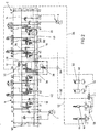
- FIG. 2 is a part of a circuit diagram of a dual-circuit control of a crawler excavator shown.
- the two-circuit control in turn has two circuits 2, 4, which can be connected to one another by means of a summing valve arrangement 12.
- Each of the circles 2, 4 supplies some consumers, with the circle 2 serving, for example, the left caterpillar, the spoon and the boom, while the circle 4 supplies the right caterpillar, the stem, the slewing gear (not shown) and an optional consumer with pressure medium ,
- Each circuit 2, 4 is associated with a variable displacement pump 6, 7, which is controlled in response to the highest in the respective circuit 2, 4 applied load pressure.
- Each of the consumers is assigned a consumer valve axis that is proportional includes adjustable directional control valve 34 through which a speed part (LUDV orifice plate 14) and a directional part are formed. Downstream of the speed part (LUDV measuring orifice 14), the LUDV pressure compensator 16 is provided which, as in the previously described embodiment, is acted upon in the opening direction by the pressure downstream of the metering orifice of the proportional valve 34 and in the closing direction by the highest load pressure in this circuit.
- the consumer valve axes assigned to other consumers have a similar structure.
- the summing axis of the summing valve assembly 12 has a summing proportional valve 36 which forms the summing orifice 26. Downstream of the summation proportional valve 36, the summation pressure compensator 28 is provided, via which the pressure drop across the summation orifice 26 can be kept constant independent of the load pressure.
- the summing valve assembly 12 is also formed with an LS-reporting valve 32, via which the LS line 18 or the LS line 20 can be switched to the pressure compensator 28.
- the dual-circuit system is manually switched to a recirculation system to ensure a sufficient and uniform pressure medium supply of the chassis and thus a straight ahead.
- This switching to a single-circuit system can in the embodiment according to FIG. 2 via a control valve 38, which in its spring-biased basic position the pump pressure leading pump lines 40, 42 of the circles 2, 4 and the two LS lines 18, 20 connects with each other.
- the control valve 38 can be switched by means of a control pressure into its passage position, wherein this control pressure is tapped as a function of the control signals generated by the operator.
- the summation proportional valve 36 of the summing axis is hydraulically controlled.
- the excavator has a large number of pilot control units in its cab, with in FIG. 2 by way of example manually operated pilot control devices 44, 46 are provided for actuating the stem and the slewing gear (pilot control device 44) and the boom and the bucket (pilot control device 46).
- the pilot units 44, 46, 48, 50 operate on the basis of directly controlled pressure reducing valves.
- control units reference is made to the literature, for example to the Bosch Rexroth data sheet RD 64 552.
- a control pressure is delivered according to the deflection, which is used to control the associated consumers.
- the output from the pilot control unit 44 for controlling the stem control pressure is tapped via a pilot line 52 and guided to a control side of the summation proportional valve 36.
- the highest of the pilot control 46 output control pressures for the operation of the boom or the spoon is a shuttle valve and a further pilot line 54 tapped and guided to the other control surface of the summation proportional valve 36.
- control pressure is tapped and guided via a control channel 60 and a switching valve 62 to a shuttle valve 64, at the other input a comparatively high, manually preselected control pressure can be applied.
- the higher of these two pressures is then guided to an effective in the opening direction control surface of the control valve 38.
- the switching valve 62 connects in its basic position the control channel 60 to the tank, so that the control valve 38 at unconfirmed pilot units 48, 50 only by the externally applied control pressure - for example, by switching a switch "Ein Vietnamese system" in its the two circles 2, 4 connecting Switching position can be switched.
- the actuation of the switching valve 62 by means of the highest, of the two foot-operated control devices 48, 50 output control pressure, which is tapped via a shuttle valve assembly 58.
- the switching valve 62 is switched to its passage position in which the highest output from the control unit 44, 46 control pressure via the control channel 60 and the Shuttle valve 64 is guided to the control valve 38 so that it can be switched independently of the voltage applied to the summing proportional valve 36 control pressure difference for connecting the two circuits 2, 4.
- This switching can be done in the above operating condition or manually by giving up the required control pressure from the outside.
- the summing proportional valve 36 has two pressure ports P1, P2 connected to the pump lines 40, 42 of the circuits 2, 4, respectively. Between the two pressure ports P1, P2 two summing S1, S2 are provided, which are connected to the summing 24 of the circuit 2 and a summing line 66 of the circuit 4.
- the summing proportional valve 36 further has an output port P "and a return port P '.
- the output port P" is connected to the input port P and the return port P' is connected to the output port A of the summing pressure gauge 28.
- the pressure in one channel between the ports P " and P is tapped via a control line and guided to an effective in the opening direction of the Summiertikwaage 28 control surface.
- the Summiertikwaage 28 is biased by an often existing, but not mandatory, weak spring and by the load pressure in its closing direction.
- This load pressure is tapped via the LS-reporting valve 32, which is designed as a proportional proportional directional control valve.
- the LS signaling valve 32 has two input terminals LS1 and LS2 and an output terminal X.
- the two input terminals LS1, LS2 are connected to the LS line 20 of the circuit 2 and the LS line 18 of the circuit 4, respectively.
- the output terminal X is connected via a control channel with a connection LS of the summation pressure compensator 28 and further with the effective in the closing direction control surface of this pressure compensator.
- the control of the LS-reporting valve 32 is carried out by tapping on the Pilot control lines 52, 54 applied control pressure difference. That is, the LS detection valve 32 is supplied with the same control pressure difference as the valve spool of the cumulative proportional valve 36.
- the proportional valve 34 has a pressure port P and an output port P 'which is connected to the input port P of the pressure compensator 16.
- the pressure applied to the connection P ' is conducted via a control line to an effective control surface of the pressure compensator 16 in the opening direction.
- the pressure compensator 16 is acted upon by a spring and by the present in the LS line 20 load pressure.
- the pressure balance 16 further has an output terminal A and a control terminal LS which is connected to the LS line 20.
- the output port A of the pressure compensator 16 is connected via a branching pressure channel with two ports P "and P" '.
- a tank connection T of the proportional valve 14 is connected to a tank channel 74 common to both circuits 2, 4.
- the control of the proportional valve 34 via control pressures, which are guided via control ports a5, b5 to the control surfaces of the proportional valve 34.
- the ports A, B, P ', P are connected to the tank port T, the ports P"', P are shut off.
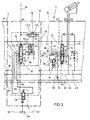
- FIG. 3 can also be removed, the summing 24 via a summing 68 and a check valve 70, which is also the function of the pressure compensator 28 downstream load-holding valve 21 from FIG. 1 fulfilled, connected to the branching part of the connection channel 76.
- the summing channel 68 opens into the branch channel 80 between the load-holding valve 82 and the associated port P ".
- a higher control pressure is applied to the port a5 than to the port b5, so that the valve spool of the proportional valve 84 as shown in FIG FIG. 3 is moved upwards.
- the connections P and P ' are connected to one another and a corresponding opening of the metering orifice 14 is set.
- the pressure medium then flows via the connection P 'to the connection P of the pressure compensator and acts on it in the opening direction.
- the pressure compensator 16 adjusts itself into a control position in which the pressure drop across the metering orifice 14 can be kept constant independent of the load pressure.
- the basic function of a LUDV consumer valve axle is known, so that further explanations are dispensable.
- the other consumer valve axes are carried out accordingly, wherein the in FIG. 2 illustrated embodiment in the circuit 2, the consumer valve axes of the spoon and the jib and in circle 4, the user's valve axis of the stem with the summing line 24 and 66 is connected.
- the consumer valve axes are not connected in both effective directions with the summing lines 24, 66, but only in the direction in which the greater pressure medium requirement is present, ie, for example, the boom in the direction of lifting.
- a summation is preferably carried out only for the pressure medium flow leading to the cylinder space.
- the summing proportional valve 36 is displaced into the positions marked (b) by the higher control pressure in the pilot control line 54, thereby opening the summing orifice 26.
- the input port P2 of the summing proportional valve 36 connected to the pump line 42 of the circuit 4 is then connected via the metering orifice 26 to the output port P ", which in turn is connected to the input port P of the summing pressure gauge 28.
- the pressure downstream of the summing orifice 26 acts in the opening direction on the Weighing plunger so that it is moved to a control position in which the input port P is connected to the output port A.
- the pressure medium then flows from this output port A via the port P 'and the directional portion of the totalizing proportional valve 36 to the summing S1, with the summing 24 of the circle 2 is connected so that the summing Consumer valve axis, ie in the present case, the boom in the circle 2 is additionally supplied with pressure medium from the circuit 4.
- the piston of the LS-reporting valve 32 in the illustration according to FIG. 3 shifted to the right, so that the LS pressure of the circuit 4 via the LS-reporting valve 32 to the effective in the closing direction control surface of the Summierdruckwaage 28 is performed.
- the summation can be performed out of phase with the respective consumer valve axis.
- Such a phase shift can be adjusted, for example, by adjusting the control range of the summation axis to an upwardly shifted range between, for example, 17 to 24 bar by suitable selection of the bias of the control springs, while the control range of the consumer valve axes is, for example, 6 to 24 bar. That is, the summation takes place only when the control pressure difference at the terminals a4 and b4 is greater than 17 bar. Up to this threshold, ie at control pressure differences smaller than 17 bar, the system operates as a two-circuit system and can only be reversed by actuation of the control valve 38 in a recirculation system.
- control valve 38 and the LS notification valve 32 are formed separately from the summation proportional valve 36.
- each axis is designed with a LUDV metering orifice 14 and a downstream LUDV pressure compensator 16, wherein some of the consumer valve axes (chassis, bucket, boom (circle 2) and handle can be summed.
- the summing valve assembly 12 in turn includes a summation proportional valve 136 with a Summiermessbrende 26 and a downstream Summierdruckwaage 28.
- the valve spool of the summation proportional valve 136 is again applied via the control terminals a4 and b4, the pilot line 52, 54 and the controllers 44, 46 with a control pressure difference to the Summation.
- the totalizing proportional valve 136 has the two pressure ports P1, P2, the summing ports S1, S2 and the port P "located downstream of the metering orifice and the return port P 'located upstream of the directional port.
- two LS connections LS1 and LS2 and a further control connection LS are provided.
- the two connections LS 1 and LS 2 are connected to the LS lines 20 and 18, the summing connections S1, S2 are connected to the summing lines 24, 66 and the two pump connections P1, P2 are connected to the pump lines 40, 42.
- connection P "leads - as in the above-described embodiment to the input connection P of the summing pressure balance 28, the output A of which is connected to the return connection P 'via a connection channel
- the pressure prevailing downstream of the metering orifice 26 is conducted via a further control line to a control surface of the pressure compensating piston which is effective in the opening direction.
- the cumulative proportional valve 136 is biased by a control spring assembly to its home position (0). In this basic position all connections are blocked. By applying a control pressure, the valve spool can be moved into the control positions indicated by (a), (b), through which the opening of the metering orifice 26 and the direction of the pressure medium flow is determined. In this respect, the function of the cumulative proportional valve 136 corresponds to that of the in FIG. 2 described embodiment. In addition to these control positions, the cumulative proportional valve 136 has a fourth switching position (c), in which the two ports P1 and P2 and LS1 and LS2 are connected to each other and all other connections are shut off.
- the valve spool of the cumulative proportional valve 136 is biased by two control spring assemblies 86, 88.
- the bias voltage - As explained above - can be chosen so that when controlling the load and the summation axis is a phase shift between the consumer valve axes and the summation axis.
- the summing proportional valve 136 has a fourth position (c). Applied via a control channel 92 and an over-control valve 94 with a high control pressure of, for example, 30 bar, a piston 90 is held on a stop. In this stop position, the control spring assembly 88 is acted upon by its basic bias, in which the valve spool is in its basic position (0).
- the control of the over-control valve 94 via a shuttle valve 96 whose function the shuttle valve 64 from FIG. 2 equivalent. That is, the input ports of the shuttle valve 96 are connected to the control port 60 (see FIG FIG. 2 ) and connected to a leading to a control unit, not shown control line over which the operator manually a control pressure can be generated.
- the larger of these two control pressures (maximum control pressure delivered by the controllers 47, 46, 50, 48, or manual control pressure) is applied to the control surface of the over-control valve 94 via the shuttle valve 96 so that it is urged against the force of a return spring (a).
- characterized switching position is movable, in which the control channel 92 is connected to the tank T.
- the high control pressure leading control line 98 is connected in the switching position (a) of the over-control valve 94 with another control channel 100, as in FIG. 4 shown below, is guided to a shuttle valve 102 whose other input port is connected to the pilot line 52. That is, the larger of the two in the further control channel 100 or the pilot line 52 applied control pressure is passed through the shuttle valve 102 to the port a4 and acts on the spool of Summing proportional valve 136 in the direction of the fourth switching position (c).
- the piston 90 When switching the over-control valve 94 in the switching position (a), the piston 90 is relieved and moved to a rear stop and correspondingly reduces the bias of the control spring assembly 88.
- the control pressure in the control line 98 is reported by means of the over-control valve 94 in the other control channel 100 and guided to the shuttle valve 102.
- the valve slide is then moved into the fourth switching position (c) in which the two pump connections P1, P2 and correspondingly also the pump lines 40 , 42 and LS1 and LS2 are interconnected - the arrangement is then switched to a single-circuit system and this mode is required, for example, when driving and simultaneously operating the equipment. That is, by this switching position (c), the function of the control valve 38 is off FIG. 2 integrated into the totalizer proportional valve.
- the cumulative proportional valve 136 is moved to one of the positions marked with (a) or (b). For example, when summing the stem (see FIG. 2 ) associated consumer valve axis, a relatively high control pressure is applied to the port a4 by actuation of the pilot control device 44, so that the valve spool is moved to one of the (a) marked positions.
- the axial displacement of the valve spool predetermines the opening of the metering orifice 26, through which the pump port P1 and output port P "are connected to each other Regulation position brought so that the input terminal P is connected to the output terminal A.
- the pressure medium flows via this output terminal A of the summing pressure balance back to the return port P 'and from there via the summing S2 in the summing line 66 and on to be summed consumer (stem).
- the feeding of the pressure medium flow to be summed takes place as in the FIG. 3 illustrated embodiment in turn via summing 68, which are connected via a check valve 70 leading to the directional part of a proportional valve 34 branch channels 78 or 80, wherein usually a summation takes place only in the direction in which there is an increased pressure medium requirement.
- the two connections LS1 and LS are connected to each other so that the LS pressure of the summing circuit 2 is applied to the pressure compensator 28.
- the pressure compensator 28 is moved to its end position, in which the LS port is connected to the port P, so that this higher pressure than new maximum load pressure is reported in the LS line 20.
- the summation of a consumer in circuit 2 is carried out by applying the higher control pressure to the port b4 in a corresponding manner, in which case the summation proportional valve is moved to the (b) marked control positions.
- the embodiment according to FIG. 5 differs from the one after the Figures 2 and 3 only by a different design of the LS-reporting valve 32. While the LS-signaling valve 32 after the Figures 2 and 3 when summing the two LS lines 18 and 20 can be separated from each other and depending on the direction of summation, the LS line 18 or the LS line 20 connects to the one control side of the pressure compensator 28, the LS-reporting valve 32 after FIG. 5 at a summation, a connection between the two LS lines 18 and 20 and between these two lines 18, 20 and the one control side of the pressure compensator 28 ago.
- the two circles 2 and 4 are always at the same pressure level, which is determined by the highest load pressure of all operated in the two circuits 2, 4 hydraulic consumers.
- the pressure level is increased in the receiving circle amount, if there is the highest load pressure is lower than the amount in the donating circle, the embodiment appears after FIG. 5 from the energy balance ago not so cheap as the embodiments of the FIGS. 2 to 4 ,
- FIG. 6a is in the two lateral switching positions of the LS-signaling valve 32 between the two LS lines 18, 20 each connected a check valve 140 which blocks from the LS line 18 of the second circuit to the LS line 20 of the first circle.
- the LS pressure in this first circuit is lower than in the second circuit, the pressure in the first circuit remains at the low level. If, on the other hand, the LS pressure in the first circuit is higher than in the second circuit, this higher LS pressure can be reported in the second circuit.
- FIG. 6b For example, the functions "connecting one control side of the pressure compensator 28 to the LS circuit of the second circuit" and “reporting a higher LS pressure of the first circuit to the second circuit" are divided into two valves 32, 33.
- the LS notification valve 32 is similar to that of the embodiment of the Figures 2 and 3 ,
- An LS-through valve 33 is controlled simultaneously with the LS-reporting valve 32 and switches depending on the direction of summation one or the other check valve 140 between the two LS lines 18, 20th
- the LS pressure of the first circuit is reported in the second circle, even if the load pressure of the summed consumer or, although lower, the LS pressure of the first circle but higher than the LS pressure of the second circle. Should it here as in the embodiments of the FIGS. 2 to 4 only on the comparison of Load pressures of summed consumers arrive with the LS pressure of the second circuit, so the highest load pressure of the summed consumers would have to be selected separately and regardless of the leading to the variable displacement LS lines in the lines 18, 20 of the Figures 6a and 6b queue.
- a hydraulic dual-circuit system for controlling consumers of a mobile device, in particular a chain device, wherein the two circuits can be summed by means of a summing valve arrangement for selected consumers.
- the pressure medium supply of the consumers takes place in each case via a LUDV measuring diaphragm and a LUDV pressure compensator.
- the summing valve arrangement is designed such that the summed volume flow from the summed circuit downstream of the metering orifice is fed into the other circuit and / or that the summation takes place relatively late, ie out of phase with the summed consumer.
Landscapes
- Engineering & Computer Science (AREA)
- General Engineering & Computer Science (AREA)
- Physics & Mathematics (AREA)
- Fluid Mechanics (AREA)
- Mechanical Engineering (AREA)
- Mining & Mineral Resources (AREA)
- Civil Engineering (AREA)
- Structural Engineering (AREA)
- Fluid-Pressure Circuits (AREA)
- Operation Control Of Excavators (AREA)
- Arrangement And Driving Of Transmission Devices (AREA)
Claims (10)
- Système hydraulique à double circuit servant à commander des récepteurs d'un appareil mobile, notamment d'un appareil à chaîne, à chaque circuit (2, 4) hydraulique étant associée une pompe à débit variable (6, 7) commandée selon la pression de charge maximale, par le biais de laquelle les récepteurs associés peuvent être alimentés en fluide sous pression et les deux circuits (2, 4) pouvant être reliés par le biais d'un ensemble de soupapes additif (12) de telle sorte que la pompe (6, 7) d'un circuit (2, 4) refoule du fluide sous pression dans l'autre circuit (4, 2) de sorte qu'au moins un récepteur raccordé à ce circuit (4, 2) puisse être alimenté par les deux pompes (6, 7) en fluide sous pression et un ensemble de soupapes LUDV avec orifice de mesure (14) et balance de pression (16) étant associé au récepteur, le fluide sous pression étant alimenté par le biais de l'ensemble de soupapes additif (12) du circuit (2, 4) raccordé par le biais d'une conduite additive (24, 66) en aval de l'orifice de mesure (14) et de la balance de pression (16) du récepteur additif et l'ensemble de soupapes additif (12) présentant une soupape proportionnelle additive (36) avec une balance de pression additive (28) montée en aval, caractérisé en ce que l'ensemble de soupapes additif (12) présente une soupape de signalisation LS (32), par le biais de laquelle un côté de commande de la balance de pression additive (28) peut être alimenté en pression de charge maximale des deux circuits ou de l'un des circuits (2, 4).
- Système à double circuit selon la revendication 1, dans lequel la conduite additive (24, 66) débouche en aval de l'orifice de mesure (14) et en amont d'une partie directionnelle d'une soupape proportionnelle (34) réalisant l'orifice de mesure (14).
- Système à double circuit selon la revendication 1 ou 2, dans lequel la commande de la soupape proportionnelle additive (36) est effectuée hydrauliquement par alimentation au moyen d'une pression de commande.
- Système à double circuit selon la revendication 3, dans lequel la pression de commande est appliquée en fonction de l'actionnement d'un bloc d'alimentation (44, 46, 48, 50) ou en fonction d'une autre logique sur la soupape proportionnelle additive (36).
- Système à double circuit selon l'une quelconque des revendications précédentes, dans lequel l'ensemble de soupapes additif (12) présente hormis la soupape proportionnelle additive (36) une soupape de commande (38), par le biais de laquelle peuvent être reliées des conduites (40, 42 ; 18, 20) des deux circuits (2, 4) guidant la pression de pompe et la pression de charge en fonction d'un signal de commande.
- Système à double circuit selon les revendications 4 et 5, dans lequel les fonctions de la soupape de signalisation LS (32) et/ou de la soupape de commande (38) sont intégrées dans la soupape proportionnelle additive (136).
- Système à double circuit selon l'une quelconque des revendications précédentes, dans lequel un tiroir principal de la soupape proportionnelle (34) associée au récepteur et de la soupape proportionnelle additive (36) est précontraint au moyen de ressorts de commande dans une position de base, la précontrainte du ressort de commande associé à la soupape proportionnelle additive (36) étant supérieure à celle de la soupape proportionnelle (34) associée au récepteur.
- Système à double circuit selon l'une quelconque des revendications précédentes, dans lequel au moins un récepteur (8, 10) additif est alimenté par le biais d'un dispositif d'étranglement (138).
- Système à double circuit selon la revendication 6, avec une soupape de surrégulation (24), par le biais de laquelle la soupape proportionnelle additive (136) peut être alimentée en un signal de commande de telle sorte que son tiroir de soupape puisse être déplacé dans une position finale (C) prédéterminée, dans laquelle les deux circuits (2, 4) sont reliés.
- Système à double circuit selon l'une quelconque des revendications précédentes, dans lequel des soupapes de retenue de charge (82, 84) sont montées en amont des récepteurs et la conduite additive (24, 66) débouche entre la soupape de retenue de charge (82, 84) et une partie directionnelle de la soupape proportionnelle (34).
Applications Claiming Priority (3)
| Application Number | Priority Date | Filing Date | Title |
|---|---|---|---|
| DE10256118 | 2002-11-29 | ||
| DE10256118 | 2002-11-29 | ||
| PCT/DE2003/003827 WO2004051092A1 (fr) | 2002-11-29 | 2003-11-19 | Systeme hydraulique a deux circuits |
Publications (2)
| Publication Number | Publication Date |
|---|---|
| EP1565658A1 EP1565658A1 (fr) | 2005-08-24 |
| EP1565658B1 true EP1565658B1 (fr) | 2008-03-19 |
Family
ID=32308894
Family Applications (1)
| Application Number | Title | Priority Date | Filing Date |
|---|---|---|---|
| EP03782096A Expired - Lifetime EP1565658B1 (fr) | 2002-11-29 | 2003-11-19 | Systeme hydraulique a deux circuits |
Country Status (8)
| Country | Link |
|---|---|
| EP (1) | EP1565658B1 (fr) |
| JP (1) | JP2006508311A (fr) |
| KR (1) | KR20050086826A (fr) |
| CN (1) | CN1314904C (fr) |
| AT (1) | ATE389813T1 (fr) |
| AU (1) | AU2003289805A1 (fr) |
| DE (2) | DE10354022A1 (fr) |
| WO (1) | WO2004051092A1 (fr) |
Cited By (1)
| Publication number | Priority date | Publication date | Assignee | Title |
|---|---|---|---|---|
| DE102011111416A1 (de) * | 2011-08-23 | 2013-02-28 | Robert Bosch Gmbh | LUDV-Energieaustauscheinrichtung mit Austauschwegeventil |
Families Citing this family (9)
| Publication number | Priority date | Publication date | Assignee | Title |
|---|---|---|---|---|
| WO2008031483A1 (fr) * | 2006-09-13 | 2008-03-20 | Robert Bosch Gmbh | Système de commande hydraulique pour l'alimentation d'un fluide sous pression régulée en fonction de la demande (régulée en fonction de la détection de la charge) de plusieurs consommateurs hydrauliques |
| DE102006053897A1 (de) * | 2006-11-15 | 2008-05-21 | Robert Bosch Gmbh | Hydraulisches Zweikreissystem und Zusammenschaltventilanordnung |
| DE102008038793A1 (de) * | 2008-04-24 | 2009-10-29 | Robert Bosch Gmbh | Hydraulisches Zweikreissystem und Verfahren zum Ansteuern von Verbrauchern eines Zweikreissystems |
| JP5791703B2 (ja) * | 2010-04-30 | 2015-10-07 | イートン コーポレーションEaton Corporation | 複合流体ポンプの組合せ回路 |
| JP5528276B2 (ja) | 2010-09-21 | 2014-06-25 | 株式会社クボタ | 作業機の油圧システム |
| US8783025B2 (en) | 2011-02-28 | 2014-07-22 | Deere & Company | Split valve pump controlled hydraulic system |
| CA2839457A1 (fr) | 2011-07-01 | 2013-01-10 | Eaton Corporation | Systemes hydrauliques utilisant des systemes combines de pompe a boucle ouverte et a boucle fermee |
| DE102012010847A1 (de) * | 2012-05-31 | 2013-12-05 | Liebherr-France Sas | Hydraulischer Steuerblock und Hydrauliksystem |
| CN107061400A (zh) * | 2017-04-17 | 2017-08-18 | 北汽福田汽车股份有限公司 | 液压控制系统和工程机械 |
Family Cites Families (5)
| Publication number | Priority date | Publication date | Assignee | Title |
|---|---|---|---|---|
| FR2689575B1 (fr) * | 1992-04-06 | 1994-07-08 | Rexroth Sigma | Distributeur hydraulique a compensation de pression et une selection de pression maximale pour piloter une pompe et commande hydraulique multiple incluant de tels distributeurs. |
| JPH06123123A (ja) * | 1992-05-22 | 1994-05-06 | Hitachi Constr Mach Co Ltd | 油圧駆動装置 |
| JPH11218102A (ja) * | 1997-11-11 | 1999-08-10 | Komatsu Ltd | 圧油供給装置 |
| JP2000087904A (ja) * | 1998-09-14 | 2000-03-28 | Komatsu Ltd | 圧油供給装置 |
| JP4212225B2 (ja) * | 2000-07-28 | 2009-01-21 | 株式会社小松製作所 | 建設機械における走行油圧回路 |
-
2003
- 2003-11-19 EP EP03782096A patent/EP1565658B1/fr not_active Expired - Lifetime
- 2003-11-19 DE DE10354022A patent/DE10354022A1/de not_active Withdrawn
- 2003-11-19 JP JP2004556006A patent/JP2006508311A/ja active Pending
- 2003-11-19 AT AT03782096T patent/ATE389813T1/de not_active IP Right Cessation
- 2003-11-19 AU AU2003289805A patent/AU2003289805A1/en not_active Abandoned
- 2003-11-19 DE DE50309431T patent/DE50309431D1/de not_active Expired - Fee Related
- 2003-11-19 KR KR1020057009439A patent/KR20050086826A/ko not_active Withdrawn
- 2003-11-19 WO PCT/DE2003/003827 patent/WO2004051092A1/fr not_active Ceased
- 2003-11-19 CN CNB2003801030818A patent/CN1314904C/zh not_active Expired - Fee Related
Cited By (1)
| Publication number | Priority date | Publication date | Assignee | Title |
|---|---|---|---|---|
| DE102011111416A1 (de) * | 2011-08-23 | 2013-02-28 | Robert Bosch Gmbh | LUDV-Energieaustauscheinrichtung mit Austauschwegeventil |
Also Published As
| Publication number | Publication date |
|---|---|
| DE50309431D1 (de) | 2008-04-30 |
| WO2004051092A1 (fr) | 2004-06-17 |
| JP2006508311A (ja) | 2006-03-09 |
| DE10354022A1 (de) | 2004-06-09 |
| CN1711426A (zh) | 2005-12-21 |
| ATE389813T1 (de) | 2008-04-15 |
| EP1565658A1 (fr) | 2005-08-24 |
| AU2003289805A1 (en) | 2004-06-23 |
| KR20050086826A (ko) | 2005-08-30 |
| CN1314904C (zh) | 2007-05-09 |
Similar Documents
| Publication | Publication Date | Title |
|---|---|---|
| DE69319400T2 (de) | Hydraulische schaltungsanordnung für erdbewegungsmaschinen | |
| DE60113002T2 (de) | Hydraulische antriebseinrichtung | |
| DE69416636T2 (de) | Flüssigkeits-Steuersystem | |
| DE102004012382B4 (de) | Hydraulische Anordnung | |
| DE112017003054B4 (de) | Hydraulisches ansteuersystem | |
| DE4100988A1 (de) | Hydraulisches antriebssystem | |
| DE4137963C2 (de) | Ventilanordnung zur lastunabhängigen Steuerung mehrerer hydraulischer Verbraucher | |
| DE19909480A1 (de) | Druckausgleichsventil, Druckentlastungsregelventil und hydraulisch betriebene Vorrichtung | |
| DE4036720C2 (de) | Steuerschaltung für die lastunabhängige Aufteilung eines Druckmittelstromes | |
| DE102012207422A1 (de) | Hydraulische Steueranordnung mit Lastdruckminderungund hydraulischer Ventilblock dafür | |
| EP1165895A1 (fr) | Dispositif de commande hydraulique sensible a une charge pour une machine de travail | |
| DE3508339C2 (fr) | ||
| EP2142808B1 (fr) | Ensemble de commande hydraulique | |
| DE102006003414B3 (de) | Hydraulische Schaltungsanordnung | |
| DE102013214734A1 (de) | Hydraulische Steueranordnung und Verfahren zur Versorgung mehrere Verbraucher damit | |
| EP1565658A1 (fr) | Systeme hydraulique a deux circuits | |
| DE19720454B4 (de) | Hydrostatisches Antriebssystem | |
| DE112022005139T5 (de) | Hydrauliksteuersystem in einer Arbeitsmaschine | |
| DE112022004868T5 (de) | Hydraulisches steuersystem in einer arbeitsmaschine | |
| WO2016091528A1 (fr) | Agencement de soupapes hydraulique, bloc de soupapes hydraulique ayant un tel agencement de soupapes, et mécanisme d'entraînement hydraulique ayant un tel bloc de soupapes hydraulique | |
| EP0656447B1 (fr) | Commande pour la répartition du fluide hydraulique pour systèmes hydrauliques avec plusieurs consommateurs | |
| EP2279354B1 (fr) | Système hydraulique à deux circuits et procédé de commande de consommateurs d'un système à deux circuits | |
| DE19603899A1 (de) | Hydraulische Steuervorrichtung zur Druckmittelversorgung mehrerer hydraulischer Verbraucher | |
| EP1558849B1 (fr) | Systeme hydraulique a double circuit | |
| DE4135013C2 (de) | Hydraulisches Antriebssystem |
Legal Events
| Date | Code | Title | Description |
|---|---|---|---|
| PUAI | Public reference made under article 153(3) epc to a published international application that has entered the european phase |
Free format text: ORIGINAL CODE: 0009012 |
|
| 17P | Request for examination filed |
Effective date: 20050406 |
|
| AK | Designated contracting states |
Kind code of ref document: A1 Designated state(s): AT BE BG CH CY CZ DE DK EE ES FI FR GB GR HU IE IT LI LU MC NL PT RO SE SI SK TR |
|
| AX | Request for extension of the european patent |
Extension state: AL LT LV MK |
|
| DAX | Request for extension of the european patent (deleted) | ||
| GRAP | Despatch of communication of intention to grant a patent |
Free format text: ORIGINAL CODE: EPIDOSNIGR1 |
|
| GRAS | Grant fee paid |
Free format text: ORIGINAL CODE: EPIDOSNIGR3 |
|
| GRAA | (expected) grant |
Free format text: ORIGINAL CODE: 0009210 |
|
| AK | Designated contracting states |
Kind code of ref document: B1 Designated state(s): AT BE BG CH CY CZ DE DK EE ES FI FR GB GR HU IE IT LI LU MC NL PT RO SE SI SK TR |
|
| REG | Reference to a national code |
Ref country code: GB Ref legal event code: FG4D Free format text: NOT ENGLISH |
|
| REG | Reference to a national code |
Ref country code: CH Ref legal event code: EP |
|
| REF | Corresponds to: |
Ref document number: 50309431 Country of ref document: DE Date of ref document: 20080430 Kind code of ref document: P |
|
| REG | Reference to a national code |
Ref country code: IE Ref legal event code: FG4D Free format text: LANGUAGE OF EP DOCUMENT: GERMAN |
|
| RAP2 | Party data changed (patent owner data changed or rights of a patent transferred) |
Owner name: BOSCH REXROTH AG |
|
| PG25 | Lapsed in a contracting state [announced via postgrant information from national office to epo] |
Ref country code: FI Free format text: LAPSE BECAUSE OF FAILURE TO SUBMIT A TRANSLATION OF THE DESCRIPTION OR TO PAY THE FEE WITHIN THE PRESCRIBED TIME-LIMIT Effective date: 20080319 |
|
| NLT2 | Nl: modifications (of names), taken from the european patent patent bulletin |
Owner name: BOSCH REXROTH AG Effective date: 20080528 |
|
| NLV1 | Nl: lapsed or annulled due to failure to fulfill the requirements of art. 29p and 29m of the patents act | ||
| PG25 | Lapsed in a contracting state [announced via postgrant information from national office to epo] |
Ref country code: SI Free format text: LAPSE BECAUSE OF FAILURE TO SUBMIT A TRANSLATION OF THE DESCRIPTION OR TO PAY THE FEE WITHIN THE PRESCRIBED TIME-LIMIT Effective date: 20080319 |
|
| REG | Reference to a national code |
Ref country code: IE Ref legal event code: FD4D |
|
| PG25 | Lapsed in a contracting state [announced via postgrant information from national office to epo] |
Ref country code: SK Free format text: LAPSE BECAUSE OF FAILURE TO SUBMIT A TRANSLATION OF THE DESCRIPTION OR TO PAY THE FEE WITHIN THE PRESCRIBED TIME-LIMIT Effective date: 20080319 Ref country code: CZ Free format text: LAPSE BECAUSE OF FAILURE TO SUBMIT A TRANSLATION OF THE DESCRIPTION OR TO PAY THE FEE WITHIN THE PRESCRIBED TIME-LIMIT Effective date: 20080319 Ref country code: PT Free format text: LAPSE BECAUSE OF FAILURE TO SUBMIT A TRANSLATION OF THE DESCRIPTION OR TO PAY THE FEE WITHIN THE PRESCRIBED TIME-LIMIT Effective date: 20080826 Ref country code: SE Free format text: LAPSE BECAUSE OF FAILURE TO SUBMIT A TRANSLATION OF THE DESCRIPTION OR TO PAY THE FEE WITHIN THE PRESCRIBED TIME-LIMIT Effective date: 20080619 Ref country code: ES Free format text: LAPSE BECAUSE OF FAILURE TO SUBMIT A TRANSLATION OF THE DESCRIPTION OR TO PAY THE FEE WITHIN THE PRESCRIBED TIME-LIMIT Effective date: 20080630 |
|
| PG25 | Lapsed in a contracting state [announced via postgrant information from national office to epo] |
Ref country code: NL Free format text: LAPSE BECAUSE OF FAILURE TO SUBMIT A TRANSLATION OF THE DESCRIPTION OR TO PAY THE FEE WITHIN THE PRESCRIBED TIME-LIMIT Effective date: 20080319 Ref country code: RO Free format text: LAPSE BECAUSE OF FAILURE TO SUBMIT A TRANSLATION OF THE DESCRIPTION OR TO PAY THE FEE WITHIN THE PRESCRIBED TIME-LIMIT Effective date: 20080319 |
|
| ET | Fr: translation filed | ||
| PLBE | No opposition filed within time limit |
Free format text: ORIGINAL CODE: 0009261 |
|
| STAA | Information on the status of an ep patent application or granted ep patent |
Free format text: STATUS: NO OPPOSITION FILED WITHIN TIME LIMIT |
|
| PG25 | Lapsed in a contracting state [announced via postgrant information from national office to epo] |
Ref country code: IE Free format text: LAPSE BECAUSE OF FAILURE TO SUBMIT A TRANSLATION OF THE DESCRIPTION OR TO PAY THE FEE WITHIN THE PRESCRIBED TIME-LIMIT Effective date: 20080319 Ref country code: DK Free format text: LAPSE BECAUSE OF FAILURE TO SUBMIT A TRANSLATION OF THE DESCRIPTION OR TO PAY THE FEE WITHIN THE PRESCRIBED TIME-LIMIT Effective date: 20080319 |
|
| 26N | No opposition filed |
Effective date: 20081222 |
|
| PGFP | Annual fee paid to national office [announced via postgrant information from national office to epo] |
Ref country code: IT Payment date: 20081124 Year of fee payment: 6 |
|
| PG25 | Lapsed in a contracting state [announced via postgrant information from national office to epo] |
Ref country code: BG Free format text: LAPSE BECAUSE OF FAILURE TO SUBMIT A TRANSLATION OF THE DESCRIPTION OR TO PAY THE FEE WITHIN THE PRESCRIBED TIME-LIMIT Effective date: 20080619 Ref country code: EE Free format text: LAPSE BECAUSE OF FAILURE TO SUBMIT A TRANSLATION OF THE DESCRIPTION OR TO PAY THE FEE WITHIN THE PRESCRIBED TIME-LIMIT Effective date: 20080319 |
|
| PGFP | Annual fee paid to national office [announced via postgrant information from national office to epo] |
Ref country code: FR Payment date: 20081118 Year of fee payment: 6 |
|
| BERE | Be: lapsed |
Owner name: BOSCH REXROTH A.G. Effective date: 20081130 |
|
| PG25 | Lapsed in a contracting state [announced via postgrant information from national office to epo] |
Ref country code: MC Free format text: LAPSE BECAUSE OF NON-PAYMENT OF DUE FEES Effective date: 20081130 |
|
| PGFP | Annual fee paid to national office [announced via postgrant information from national office to epo] |
Ref country code: GB Payment date: 20081121 Year of fee payment: 6 |
|
| REG | Reference to a national code |
Ref country code: CH Ref legal event code: PL |
|
| PG25 | Lapsed in a contracting state [announced via postgrant information from national office to epo] |
Ref country code: CY Free format text: LAPSE BECAUSE OF FAILURE TO SUBMIT A TRANSLATION OF THE DESCRIPTION OR TO PAY THE FEE WITHIN THE PRESCRIBED TIME-LIMIT Effective date: 20080319 Ref country code: BE Free format text: LAPSE BECAUSE OF NON-PAYMENT OF DUE FEES Effective date: 20081130 |
|
| PG25 | Lapsed in a contracting state [announced via postgrant information from national office to epo] |
Ref country code: DE Free format text: LAPSE BECAUSE OF NON-PAYMENT OF DUE FEES Effective date: 20090603 Ref country code: LI Free format text: LAPSE BECAUSE OF NON-PAYMENT OF DUE FEES Effective date: 20081130 Ref country code: CH Free format text: LAPSE BECAUSE OF NON-PAYMENT OF DUE FEES Effective date: 20081130 |
|
| PG25 | Lapsed in a contracting state [announced via postgrant information from national office to epo] |
Ref country code: AT Free format text: LAPSE BECAUSE OF NON-PAYMENT OF DUE FEES Effective date: 20081119 |
|
| GBPC | Gb: european patent ceased through non-payment of renewal fee |
Effective date: 20091119 |
|
| PG25 | Lapsed in a contracting state [announced via postgrant information from national office to epo] |
Ref country code: LU Free format text: LAPSE BECAUSE OF NON-PAYMENT OF DUE FEES Effective date: 20081119 Ref country code: HU Free format text: LAPSE BECAUSE OF FAILURE TO SUBMIT A TRANSLATION OF THE DESCRIPTION OR TO PAY THE FEE WITHIN THE PRESCRIBED TIME-LIMIT Effective date: 20080920 |
|
| REG | Reference to a national code |
Ref country code: FR Ref legal event code: ST Effective date: 20100730 |
|
| PG25 | Lapsed in a contracting state [announced via postgrant information from national office to epo] |
Ref country code: TR Free format text: LAPSE BECAUSE OF FAILURE TO SUBMIT A TRANSLATION OF THE DESCRIPTION OR TO PAY THE FEE WITHIN THE PRESCRIBED TIME-LIMIT Effective date: 20080319 |
|
| PG25 | Lapsed in a contracting state [announced via postgrant information from national office to epo] |
Ref country code: GR Free format text: LAPSE BECAUSE OF FAILURE TO SUBMIT A TRANSLATION OF THE DESCRIPTION OR TO PAY THE FEE WITHIN THE PRESCRIBED TIME-LIMIT Effective date: 20080620 Ref country code: FR Free format text: LAPSE BECAUSE OF NON-PAYMENT OF DUE FEES Effective date: 20091130 |
|
| PG25 | Lapsed in a contracting state [announced via postgrant information from national office to epo] |
Ref country code: GB Free format text: LAPSE BECAUSE OF NON-PAYMENT OF DUE FEES Effective date: 20091119 |
|
| PG25 | Lapsed in a contracting state [announced via postgrant information from national office to epo] |
Ref country code: IT Free format text: LAPSE BECAUSE OF NON-PAYMENT OF DUE FEES Effective date: 20091119 |