EP1565764B1 - Dispositif de mesure sensible a l'emplacement spatial - Google Patents
Dispositif de mesure sensible a l'emplacement spatial Download PDFInfo
- Publication number
- EP1565764B1 EP1565764B1 EP03778257A EP03778257A EP1565764B1 EP 1565764 B1 EP1565764 B1 EP 1565764B1 EP 03778257 A EP03778257 A EP 03778257A EP 03778257 A EP03778257 A EP 03778257A EP 1565764 B1 EP1565764 B1 EP 1565764B1
- Authority
- EP
- European Patent Office
- Prior art keywords
- pmt
- light
- measuring device
- channels
- channel
- Prior art date
- Legal status (The legal status is an assumption and is not a legal conclusion. Google has not performed a legal analysis and makes no representation as to the accuracy of the status listed.)
- Expired - Lifetime
Links
Images

Classifications
-
- G—PHYSICS
- G01—MEASURING; TESTING
- G01T—MEASUREMENT OF NUCLEAR OR X-RADIATION
- G01T1/00—Measuring X-radiation, gamma radiation, corpuscular radiation, or cosmic radiation
- G01T1/29—Measurement performed on radiation beams, e.g. position or section of the beam; Measurement of spatial distribution of radiation
- G01T1/2914—Measurement of spatial distribution of radiation
- G01T1/2921—Static instruments for imaging the distribution of radioactivity in one or two dimensions; Radio-isotope cameras
-
- G—PHYSICS
- G01—MEASURING; TESTING
- G01J—MEASUREMENT OF INTENSITY, VELOCITY, SPECTRAL CONTENT, POLARISATION, PHASE OR PULSE CHARACTERISTICS OF INFRARED, VISIBLE OR ULTRAVIOLET LIGHT; COLORIMETRY; RADIATION PYROMETRY
- G01J1/00—Photometry, e.g. photographic exposure meter
- G01J1/42—Photometry, e.g. photographic exposure meter using electric radiation detectors
-
- H—ELECTRICITY
- H01—ELECTRIC ELEMENTS
- H01J—ELECTRIC DISCHARGE TUBES OR DISCHARGE LAMPS
- H01J31/00—Cathode ray tubes; Electron beam tubes
- H01J31/08—Cathode ray tubes; Electron beam tubes having a screen on or from which an image or pattern is formed, picked up, converted, or stored
- H01J31/50—Image-conversion or image-amplification tubes, i.e. having optical, X-ray, or analogous input, and optical output
- H01J31/506—Image-conversion or image-amplification tubes, i.e. having optical, X-ray, or analogous input, and optical output tubes using secondary emission effect
- H01J31/507—Image-conversion or image-amplification tubes, i.e. having optical, X-ray, or analogous input, and optical output tubes using secondary emission effect using a large number of channels, e.g. microchannel plates
Definitions
- the invention relates to a measuring device with a spatially resolving multi-channel secondary electron multiplier (MC-PMT) for converting light into an electrical signal.
- MC-PMT multi-channel secondary electron multiplier
- Such a measuring device is for example off Y. Shao, RW Silverman, SR Cherry, "Evaluation of Hamamatsu R5900 series PMTs for readout of high-resolution scintillator arrays", Nucl. Instr. Meth. A 454 (2000), 279-299 and Y. Yoshizawa, H. Ohtsu, N. Ota, T. Watanabe, J. Takeuchi, "The development and the study of R5900-00-M64 for scintillating / optical fiber read out", 1997 IEEE Nuclear Science Symposium Conference Record, Albuquerque , NM known. Incident ⁇ radiation is converted by a converter into flashes of light.
- the flashes of light strike a photocathode of the MC-PMT.
- electrons leak out of the cathode and are amplified in the electron multiplier (dynode stages) to an electrical measurement signal. In this way it is possible to determine the radiation intensity and the energy of the radiation depending on the location.
- the known location-sensitive measuring devices have the disadvantage that the incident radiation as a function of the location of the impact of the ⁇ -radiation on the converter cause a different strong measurement signal.
- This apparatus-related, location-dependent Differences are made higher demands on the subsequent electronics.
- PMTs can convert minute light events into electrical signals by accelerating individual photon-triggered electrons in the vacuum of the photomultiplier tube and generating an avalanche of secondary electrons at so-called dynodes.
- MC-PMT multichannel photomultipliers
- the electron multiplying stages (dynodes) are formed into individual channels. Each entry region on the photocathode is thus assigned an anode pin at the output.
- the MC-PMT behaves like a multitude of densely packed single PMTs.
- the charges arriving at the individual anodes of the channels thus represent a considerably amplified image of the light distribution on the photocathode, a location-accurate assignment of the light events corresponding to the raster formed by the channels being given.
- PMT for example, a spatially resolved detection of scintillation events, as required for nuclear medicine, can be achieved.
- optical crosstalk between adjacent channels may occur.
- the light Upon illumination of a pixel of the photo-cathode, for example by optical fibers, the light passes through scattering in the cathode window and reflections in the photomultiplier tube to a small extent in adjacent channels, resulting in optical crosstalk.
- the optical crosstalk between adjacent channels depends on design-related properties of the photomultiplier tube, such as the thickness of the cathode window, and on the type of coupling, for example the fibers and has a disturbing effect on the resolution of the PMT.
- For precise positioning of the optical fibers above the centers of the channels Y. Shao, SR Cherry, S. Siegel, RW Silverman, S.
- the location information is achieved through the use of individual channels with a corresponding readout electronics.
- a disadvantage arises in these detectors, the problem of different depending on the lighting location measuring signals.
- the measuring signals do not change continuously, but between the individual channels.
- Out DE 196 02 177 C 2 is a location-sensitive measuring device, in which the problem of individually different strength measuring signals is reduced in a simple manner known.
- a film, a film, a glass sheet or an LCD layer for light attenuation that is, for light absorption is provided.
- the degree of light attenuation (absorption degree) varies depending on the location.
- the film, the film, the glass sheet or the LCD layer have areas of different degrees of blackening.
- the degree of blackening, and thus the degree of absorption is the more dependent on the location, the greater the apparatus-related measuring signals which the measuring device would have output without the light attenuation at these locations.
- the disadvantage is also a maximum blackened film still pass a certain amount of light. This leads in particular to those places where maximum light attenuation is required to false (too high) measurement results. In those places where undiminished passage of the light would be desirable, the use of a film, albeit un-blackened, results in still undesirable light attenuation resulting in low measurement results.
- the object of the invention is to provide a measuring device to be provided with the apparatus-related, location-dependent differences of the output signals are prevented, and such spatially resolved measurement signals as they are emitted from a sample to be examined.
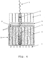
- the measuring device comprises a MC-PMT and a light-impermeable shadow mask.
- the measuring device according to the invention is the light impermeable shadow mask regularly between the converter and the MC-PMT.
- the opaque shadow mask is completely impermeable to light. It has holes of different sizes. This causes improved light attenuation devices to be improved compared to prior art devices.
- the output signals of the MC-PMT can be homogenized by a suitable choice of the shadow mask, and then no longer influenced by equipment-related conditions. For a particular measuring device, the degree of light attenuation by location of the hole size is selected depending on the location so that device-related, location-dependent differences of the electrical measurement signals are thereby reduced.
- the light-impermeable shadow mask is advantageously made of a metal, for.
- a metal for.
- nickel silver alloy of tin, zinc and copper.
- Such metals are impermeable to light and easy to process into a shadow mask. It is of course also possible to use a corresponding other metal.
- the light-impermeable shadow mask advantageously has a thickness of about 50 ⁇ m, depending on the material. This ensures, for example, that the mask is flexible enough to adapt to any surface curvature of the MC-PMT.
- the number of holes in the mask is advantageously dependent on the number of individual channels of the MC-PMT.
- An MC-PMT with x channels advantageously has a light-impermeable shadow mask with also x holes. As a result, a hole can be assigned to each channel of a shadow mask become.
- the geometry of the holes is not fixed. Suitable geometries are, for example, circles or even squares.
- all holes of a shadow mask have the same geometry.
- the size of individual holes of the mask varies depending on the sensitivity of the individual channels of the MC-PMT.
- a channel, which generates a large apparatus-related measurement signal, a small hole is assigned.
- a channel which generates a small apparatus-related measurement signal is assigned a large hole.
- the holes of the light-impermeable mask act as diaphragms to equalize the gain of the channels of an MC-PMT and homogenize instrumental differences in the measurement signals.
- the holes of the mask are arranged in front of the channels of the MC-PMT such that the incident light passes through the holes and is limited in each case to the middle of the channels of the MC-PMT. This advantageously works to reduce crosstalk of light between adjacent channels.
- a PMT in particular with a multiplicity of individual channels and in particular with 64 channels, is provided as MC-PMT.
- the light-impermeable shadow mask as a diaphragm arrangement, so arranged between the PMT as MC-PMT and the converter that the light entering the channels is limited to each of the channel center.
- the crosstalk of light between adjacent channels is greatly reduced.
- the detector Since the detector has individual channels, it is possible to measure the detectors necessary for the creation of the masks in comparison to DE 196 02 177 C2 greatly simplify.
- the detector surface is illuminated uniformly while the signals are measured at the individual channels. An expensive and time-consuming scanning of the detector is eliminated.
- Measurement results obtained with such measuring arrangements show a particularly good homogenization of the output signals and a strong suppression of crosstalk.
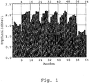
- the MC-PMT are measured using a blue LED. This shows without a light-impermeable shadow mask between photocathode and PMT a very inhomogeneous sensitivity pattern of the individual channels of the MC-PMT.
- FIG. 1 shows an example of the 64 channels of a PMT whose relative sensitivity varies between 1.0 and 2.5. For example, channel 57 has sensitivity 1 and channel 31 sensitivity 2.5.
- a corresponding shadow mask is made for only one MC-PMT.
- Each channel receives an aperture whose opening area is inversely proportional to the previously measured sensitivity.
- the maximum aperture size is set previously and assigned to the least sensitive anode.
- the masks are made of a light-impermeable material, e.g. As metal or plastic, made in any thickness.
- a light-impermeable material e.g. As metal or plastic, made in any thickness.
- the method for creating the holes can also be used on conventional manufacturing methods.
- the measured sensitivities of the individual channels of the MC-PMT are used to create the opaque shadow masks
- Fig. 2 shows the template for such a light-impermeable shadow mask for a particular MC-PMT, the maximum hole size being 2 x 2 mm 2 (this corresponds to the least sensitive channel).
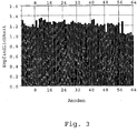
- Measuring the sensitivities and converting these values to a hole template is done individually and accurately for each MC-PMT. Such a metal mask homogenizes the sensitivity of the PMT, as in figure 3 shown. The relative sensitivity for the least sensitive channel remains at 1.0, the maximum value after compensation is 1.3.
- the invention relates to PMT of the MC-PMT type.
Landscapes
- Physics & Mathematics (AREA)
- General Physics & Mathematics (AREA)
- Spectroscopy & Molecular Physics (AREA)
- Health & Medical Sciences (AREA)
- Life Sciences & Earth Sciences (AREA)
- High Energy & Nuclear Physics (AREA)
- Molecular Biology (AREA)
- Measurement Of Radiation (AREA)
- Photometry And Measurement Of Optical Pulse Characteristics (AREA)
- Measurement Of The Respiration, Hearing Ability, Form, And Blood Characteristics Of Living Organisms (AREA)
Claims (7)
- Dispositif de mesure comportant un photomultiplicateur à plusieurs canaux (MC-PMT) (10) à résolution spatiale servant à convertir de la lumière en des signaux de mesure électriques dépendant de la localisation, comportant un masque perforé (4) imperméable à la lumière devant le MC-PMT (10), sachant que les alésages du masque perforé imperméable à la lumière sont disposés devant les canaux du PMT, caractérisé en ce que le masque perforé présente des alésages de taille différente, sachant que la taille des alésages est choisie en fonction de la localisation de telle sorte que des différences des signaux de mesure électriques inhérentes à la localisation, dues aux appareillages sont ainsi atténuées.
- Dispositif de mesure selon la revendication précédente,
caractérisé par
un masque perforé imperméable à la lumière en métal, de préférence en argentan. - Dispositif de mesure selon l'une quelconque des revendications précédentes,
caractérisé par
un masque perforé présentant une épaisseur de 50 µm. - Dispositif de mesure selon l'une quelconque des revendications précédentes,
caractérisé en ce que
le masque perforé comporte une multitude d'alésages, laquelle est identique à la multitude de canaux du MC-PMT. - Dispositif de mesure selon l'une quelconque des revendications précédentes,
caractérisé en ce que
les alésages du masque perforé sont disposés de telle manière devant les canaux du MC-PMT que la lumière entrante est concentrée sur la moitié de chaque canal de sorte qu'on évite une intermodulation entre les canaux. - Dispositif de mesure selon l'une quelconque des revendications précédentes,
caractérisé en ce que
la taille d'un alésage est inversement proportionnelle à la sensibilité d'un canal associé. - Dispositif de mesure selon l'une quelconque des revendications précédentes,
caractérisé par
un photomultiplicateur à plusieurs canaux ou par une pluralité de photomultiplicateurs à plusieurs canaux (MC-PMT) (10).
Applications Claiming Priority (3)
| Application Number | Priority Date | Filing Date | Title |
|---|---|---|---|
| DE10255245 | 2002-11-26 | ||
| DE10255245A DE10255245A1 (de) | 2002-11-26 | 2002-11-26 | Ortsempfindliche Meßeinrichtung |
| PCT/DE2003/003733 WO2004049003A1 (fr) | 2002-11-26 | 2003-11-12 | Dispositif de mesure sensible a l'emplacement spatial |
Publications (2)
| Publication Number | Publication Date |
|---|---|
| EP1565764A1 EP1565764A1 (fr) | 2005-08-24 |
| EP1565764B1 true EP1565764B1 (fr) | 2012-05-09 |
Family
ID=32308736
Family Applications (1)
| Application Number | Title | Priority Date | Filing Date |
|---|---|---|---|
| EP03778257A Expired - Lifetime EP1565764B1 (fr) | 2002-11-26 | 2003-11-12 | Dispositif de mesure sensible a l'emplacement spatial |
Country Status (4)
| Country | Link |
|---|---|
| EP (1) | EP1565764B1 (fr) |
| AT (1) | ATE557414T1 (fr) |
| DE (1) | DE10255245A1 (fr) |
| WO (1) | WO2004049003A1 (fr) |
Family Cites Families (7)
| Publication number | Priority date | Publication date | Assignee | Title |
|---|---|---|---|---|
| US4092540A (en) * | 1976-10-26 | 1978-05-30 | Raytheon Company | Radiographic camera with internal mask |
| DE3533582A1 (de) * | 1985-09-20 | 1987-04-02 | Messerschmitt Boelkow Blohm | Bildsensor zur aufnahme von szenen oder objekten mit tiefenstrukturierter oberflaeche |
| NL8900040A (nl) | 1989-01-09 | 1990-08-01 | Philips Nv | Roentgenbeeldversterkerbuis met selectief filter. |
| DE4032193A1 (de) * | 1990-10-08 | 1992-04-09 | Iwg Eastmed Medizintechnik Gmb | Optoelektronische kamera |
| JPH04274793A (ja) * | 1991-02-28 | 1992-09-30 | Shimadzu Corp | 放射線検出器 |
| DE4311982A1 (de) * | 1992-04-08 | 1993-10-14 | Peter Dipl Ing Diedrich | Optoelektronische Kamera |
| DE19602177C2 (de) * | 1996-01-23 | 1998-12-17 | Forschungszentrum Juelich Gmbh | Ortsempfindliche Meßeinrichtung |
-
2002
- 2002-11-26 DE DE10255245A patent/DE10255245A1/de not_active Withdrawn
-
2003
- 2003-11-12 AT AT03778257T patent/ATE557414T1/de active
- 2003-11-12 EP EP03778257A patent/EP1565764B1/fr not_active Expired - Lifetime
- 2003-11-12 WO PCT/DE2003/003733 patent/WO2004049003A1/fr not_active Ceased
Also Published As
| Publication number | Publication date |
|---|---|
| WO2004049003A1 (fr) | 2004-06-10 |
| EP1565764A1 (fr) | 2005-08-24 |
| ATE557414T1 (de) | 2012-05-15 |
| DE10255245A1 (de) | 2004-06-09 |
Similar Documents
| Publication | Publication Date | Title |
|---|---|---|
| EP0909947B1 (fr) | Système de mesure optique pour la détection d'émissions luminescentes ou fluorescentes | |
| EP1569012B1 (fr) | Procédé pour la détection de rayonnement ionisant | |
| DE69300980T2 (de) | Bildverstärkerröhre, insbesondere für Nahfokusröhre | |
| DE2605865A1 (de) | Streak-kamera-roehre | |
| CA1119316A (fr) | Camera a rayons gamma | |
| DE3709298C2 (fr) | ||
| DE2453772A1 (de) | Schnellansprechende kamera fuer bildwandlerroehren | |
| DE3704716A1 (de) | Ortsempfindlicher detektor | |
| DE112020006001T5 (de) | Ladungsträgerdetektor, ladungsträgerstrahlvorrichtung, strahlungsdetektor und strahlungsdetektionsvorrichtung | |
| DE69615242T2 (de) | Mikrokanalplatte und Photovervielfacherröhre | |
| DE69412159T2 (de) | Streifen - Elektronenstrahlröhre | |
| DE3785932T2 (de) | Optische abbildungsvorrichtung mit hoher auflösung. | |
| DE3638893C2 (fr) | ||
| DE2610751A1 (de) | Vorrichtung zur lokalisation von lichterscheinungen | |
| EP1565764B1 (fr) | Dispositif de mesure sensible a l'emplacement spatial | |
| DE102011077057A1 (de) | Strahlungsdetektor und bildgebendes System | |
| DE1030939B (de) | Bildverstaerker mit einem zwischen dem ein Elektronenbild aussendenden Eingangsschirm und dem Phosphoreszenzschirm angeordneten Elektronenverstaerkungsschirm | |
| DE4223773C2 (de) | Verfahren zur Unterscheidung und gleichzeitigen oder getrennten Messung von Einzel- und Mehrelektronenereignissen in einem optoelektronischen Detektor | |
| DE2750132C2 (fr) | ||
| WO2010094272A2 (fr) | Gamma-caméra spect, scanner spect et utilisations d'une gamma-caméra spect | |
| DE3042980A1 (de) | Temporal disperse sensorroehre | |
| JPH0424672B2 (fr) | ||
| DE69604635T2 (de) | Elektronenröhre | |
| DE69613131T2 (de) | Röntgenbilddetektor und Bildauslesevorrichtung | |
| DE19602177C2 (de) | Ortsempfindliche Meßeinrichtung |
Legal Events
| Date | Code | Title | Description |
|---|---|---|---|
| PUAI | Public reference made under article 153(3) epc to a published international application that has entered the european phase |
Free format text: ORIGINAL CODE: 0009012 |
|
| 17P | Request for examination filed |
Effective date: 20050507 |
|
| AK | Designated contracting states |
Kind code of ref document: A1 Designated state(s): AT BE BG CH CY CZ DE DK EE ES FI FR GB GR HU IE IT LI LU MC NL PT RO SE SI SK TR |
|
| RIN1 | Information on inventor provided before grant (corrected) |
Inventor name: LARUE, HORST Inventor name: STREUN, MATTHIAS Inventor name: CHRIST, DANIELA Inventor name: WEBER, SIMONE |
|
| RIN1 | Information on inventor provided before grant (corrected) |
Inventor name: LARUE, HORST Inventor name: CHRIST, DANIELA Inventor name: STREUN, MATTHIAS Inventor name: WEBER, SIMONE |
|
| 17Q | First examination report despatched |
Effective date: 20110824 |
|
| REG | Reference to a national code |
Ref country code: DE Ref legal event code: R079 Ref document number: 50314334 Country of ref document: DE Free format text: PREVIOUS MAIN CLASS: G01T0001290000 Ipc: H01J0031500000 |
|
| GRAP | Despatch of communication of intention to grant a patent |
Free format text: ORIGINAL CODE: EPIDOSNIGR1 |
|
| RIC1 | Information provided on ipc code assigned before grant |
Ipc: H01J 31/50 20060101AFI20111201BHEP Ipc: G01T 1/29 20060101ALI20111201BHEP Ipc: G01J 1/42 20060101ALI20111201BHEP |
|
| RAP1 | Party data changed (applicant data changed or rights of an application transferred) |
Owner name: FORSCHUNGSZENTRUM JUELICH GMBH |
|
| RIN1 | Information on inventor provided before grant (corrected) |
Inventor name: BEER, SIMONE Inventor name: CHRIST, DANIELA Inventor name: STREUN, MATTHIAS Inventor name: LARUE, HORST |
|
| GRAS | Grant fee paid |
Free format text: ORIGINAL CODE: EPIDOSNIGR3 |
|
| RIN1 | Information on inventor provided before grant (corrected) |
Inventor name: LARUE, HORST Inventor name: CHRIST, DANIELA Inventor name: STREUN, MATTHIAS Inventor name: BEER, SIMONE |
|
| GRAA | (expected) grant |
Free format text: ORIGINAL CODE: 0009210 |
|
| AK | Designated contracting states |
Kind code of ref document: B1 Designated state(s): AT BE BG CH CY CZ DE DK EE ES FI FR GB GR HU IE IT LI LU MC NL PT RO SE SI SK TR |
|
| REG | Reference to a national code |
Ref country code: GB Ref legal event code: FG4D Free format text: NOT ENGLISH |
|
| REG | Reference to a national code |
Ref country code: CH Ref legal event code: EP Ref country code: AT Ref legal event code: REF Ref document number: 557414 Country of ref document: AT Kind code of ref document: T Effective date: 20120515 |
|
| REG | Reference to a national code |
Ref country code: IE Ref legal event code: FG4D Free format text: LANGUAGE OF EP DOCUMENT: GERMAN |
|
| REG | Reference to a national code |
Ref country code: DE Ref legal event code: R096 Ref document number: 50314334 Country of ref document: DE Effective date: 20120705 |
|
| REG | Reference to a national code |
Ref country code: NL Ref legal event code: VDEP Effective date: 20120509 |
|
| PG25 | Lapsed in a contracting state [announced via postgrant information from national office to epo] |
Ref country code: FI Free format text: LAPSE BECAUSE OF FAILURE TO SUBMIT A TRANSLATION OF THE DESCRIPTION OR TO PAY THE FEE WITHIN THE PRESCRIBED TIME-LIMIT Effective date: 20120509 Ref country code: SE Free format text: LAPSE BECAUSE OF FAILURE TO SUBMIT A TRANSLATION OF THE DESCRIPTION OR TO PAY THE FEE WITHIN THE PRESCRIBED TIME-LIMIT Effective date: 20120509 Ref country code: CY Free format text: LAPSE BECAUSE OF FAILURE TO SUBMIT A TRANSLATION OF THE DESCRIPTION OR TO PAY THE FEE WITHIN THE PRESCRIBED TIME-LIMIT Effective date: 20120509 |
|
| PG25 | Lapsed in a contracting state [announced via postgrant information from national office to epo] |
Ref country code: SI Free format text: LAPSE BECAUSE OF FAILURE TO SUBMIT A TRANSLATION OF THE DESCRIPTION OR TO PAY THE FEE WITHIN THE PRESCRIBED TIME-LIMIT Effective date: 20120509 Ref country code: GR Free format text: LAPSE BECAUSE OF FAILURE TO SUBMIT A TRANSLATION OF THE DESCRIPTION OR TO PAY THE FEE WITHIN THE PRESCRIBED TIME-LIMIT Effective date: 20120810 Ref country code: PT Free format text: LAPSE BECAUSE OF FAILURE TO SUBMIT A TRANSLATION OF THE DESCRIPTION OR TO PAY THE FEE WITHIN THE PRESCRIBED TIME-LIMIT Effective date: 20120910 |
|
| PG25 | Lapsed in a contracting state [announced via postgrant information from national office to epo] |
Ref country code: RO Free format text: LAPSE BECAUSE OF FAILURE TO SUBMIT A TRANSLATION OF THE DESCRIPTION OR TO PAY THE FEE WITHIN THE PRESCRIBED TIME-LIMIT Effective date: 20120509 Ref country code: CZ Free format text: LAPSE BECAUSE OF FAILURE TO SUBMIT A TRANSLATION OF THE DESCRIPTION OR TO PAY THE FEE WITHIN THE PRESCRIBED TIME-LIMIT Effective date: 20120509 Ref country code: SK Free format text: LAPSE BECAUSE OF FAILURE TO SUBMIT A TRANSLATION OF THE DESCRIPTION OR TO PAY THE FEE WITHIN THE PRESCRIBED TIME-LIMIT Effective date: 20120509 Ref country code: EE Free format text: LAPSE BECAUSE OF FAILURE TO SUBMIT A TRANSLATION OF THE DESCRIPTION OR TO PAY THE FEE WITHIN THE PRESCRIBED TIME-LIMIT Effective date: 20120509 Ref country code: DK Free format text: LAPSE BECAUSE OF FAILURE TO SUBMIT A TRANSLATION OF THE DESCRIPTION OR TO PAY THE FEE WITHIN THE PRESCRIBED TIME-LIMIT Effective date: 20120509 Ref country code: NL Free format text: LAPSE BECAUSE OF FAILURE TO SUBMIT A TRANSLATION OF THE DESCRIPTION OR TO PAY THE FEE WITHIN THE PRESCRIBED TIME-LIMIT Effective date: 20120509 |
|
| PG25 | Lapsed in a contracting state [announced via postgrant information from national office to epo] |
Ref country code: IT Free format text: LAPSE BECAUSE OF FAILURE TO SUBMIT A TRANSLATION OF THE DESCRIPTION OR TO PAY THE FEE WITHIN THE PRESCRIBED TIME-LIMIT Effective date: 20120509 |
|
| PLBE | No opposition filed within time limit |
Free format text: ORIGINAL CODE: 0009261 |
|
| STAA | Information on the status of an ep patent application or granted ep patent |
Free format text: STATUS: NO OPPOSITION FILED WITHIN TIME LIMIT |
|
| 26N | No opposition filed |
Effective date: 20130212 |
|
| PG25 | Lapsed in a contracting state [announced via postgrant information from national office to epo] |
Ref country code: ES Free format text: LAPSE BECAUSE OF FAILURE TO SUBMIT A TRANSLATION OF THE DESCRIPTION OR TO PAY THE FEE WITHIN THE PRESCRIBED TIME-LIMIT Effective date: 20120820 |
|
| BERE | Be: lapsed |
Owner name: FORSCHUNGSZENTRUM JULICH G.M.B.H. Effective date: 20121130 |
|
| REG | Reference to a national code |
Ref country code: DE Ref legal event code: R097 Ref document number: 50314334 Country of ref document: DE Effective date: 20130212 |
|
| GBPC | Gb: european patent ceased through non-payment of renewal fee |
Effective date: 20121112 |
|
| PG25 | Lapsed in a contracting state [announced via postgrant information from national office to epo] |
Ref country code: BG Free format text: LAPSE BECAUSE OF FAILURE TO SUBMIT A TRANSLATION OF THE DESCRIPTION OR TO PAY THE FEE WITHIN THE PRESCRIBED TIME-LIMIT Effective date: 20120809 |
|
| REG | Reference to a national code |
Ref country code: IE Ref legal event code: MM4A |
|
| PG25 | Lapsed in a contracting state [announced via postgrant information from national office to epo] |
Ref country code: BE Free format text: LAPSE BECAUSE OF NON-PAYMENT OF DUE FEES Effective date: 20121130 |
|
| PG25 | Lapsed in a contracting state [announced via postgrant information from national office to epo] |
Ref country code: IE Free format text: LAPSE BECAUSE OF NON-PAYMENT OF DUE FEES Effective date: 20121112 |
|
| PG25 | Lapsed in a contracting state [announced via postgrant information from national office to epo] |
Ref country code: GB Free format text: LAPSE BECAUSE OF NON-PAYMENT OF DUE FEES Effective date: 20121112 |
|
| REG | Reference to a national code |
Ref country code: AT Ref legal event code: MM01 Ref document number: 557414 Country of ref document: AT Kind code of ref document: T Effective date: 20121130 |
|
| PG25 | Lapsed in a contracting state [announced via postgrant information from national office to epo] |
Ref country code: AT Free format text: LAPSE BECAUSE OF NON-PAYMENT OF DUE FEES Effective date: 20121130 |
|
| PG25 | Lapsed in a contracting state [announced via postgrant information from national office to epo] |
Ref country code: TR Free format text: LAPSE BECAUSE OF FAILURE TO SUBMIT A TRANSLATION OF THE DESCRIPTION OR TO PAY THE FEE WITHIN THE PRESCRIBED TIME-LIMIT Effective date: 20120509 Ref country code: MC Free format text: LAPSE BECAUSE OF NON-PAYMENT OF DUE FEES Effective date: 20121130 |
|
| PG25 | Lapsed in a contracting state [announced via postgrant information from national office to epo] |
Ref country code: LU Free format text: LAPSE BECAUSE OF NON-PAYMENT OF DUE FEES Effective date: 20121112 |
|
| PG25 | Lapsed in a contracting state [announced via postgrant information from national office to epo] |
Ref country code: HU Free format text: LAPSE BECAUSE OF FAILURE TO SUBMIT A TRANSLATION OF THE DESCRIPTION OR TO PAY THE FEE WITHIN THE PRESCRIBED TIME-LIMIT Effective date: 20031112 |
|
| PGFP | Annual fee paid to national office [announced via postgrant information from national office to epo] |
Ref country code: DE Payment date: 20141011 Year of fee payment: 12 Ref country code: CH Payment date: 20141120 Year of fee payment: 12 |
|
| PGFP | Annual fee paid to national office [announced via postgrant information from national office to epo] |
Ref country code: FR Payment date: 20141118 Year of fee payment: 12 |
|
| REG | Reference to a national code |
Ref country code: DE Ref legal event code: R119 Ref document number: 50314334 Country of ref document: DE |
|
| REG | Reference to a national code |
Ref country code: CH Ref legal event code: PL |
|
| PG25 | Lapsed in a contracting state [announced via postgrant information from national office to epo] |
Ref country code: CH Free format text: LAPSE BECAUSE OF NON-PAYMENT OF DUE FEES Effective date: 20151130 Ref country code: LI Free format text: LAPSE BECAUSE OF NON-PAYMENT OF DUE FEES Effective date: 20151130 |
|
| REG | Reference to a national code |
Ref country code: FR Ref legal event code: ST Effective date: 20160729 |
|
| PG25 | Lapsed in a contracting state [announced via postgrant information from national office to epo] |
Ref country code: DE Free format text: LAPSE BECAUSE OF NON-PAYMENT OF DUE FEES Effective date: 20160601 |
|
| PG25 | Lapsed in a contracting state [announced via postgrant information from national office to epo] |
Ref country code: FR Free format text: LAPSE BECAUSE OF NON-PAYMENT OF DUE FEES Effective date: 20151130 |