EP1566355A1 - Procédé et dispositif pour diviser une pile de feuilles - Google Patents
Procédé et dispositif pour diviser une pile de feuilles Download PDFInfo
- Publication number
- EP1566355A1 EP1566355A1 EP04003972A EP04003972A EP1566355A1 EP 1566355 A1 EP1566355 A1 EP 1566355A1 EP 04003972 A EP04003972 A EP 04003972A EP 04003972 A EP04003972 A EP 04003972A EP 1566355 A1 EP1566355 A1 EP 1566355A1
- Authority
- EP
- European Patent Office
- Prior art keywords
- stack
- pliers
- partial
- gripping means
- holding
- Prior art date
- Legal status (The legal status is an assumption and is not a legal conclusion. Google has not performed a legal analysis and makes no representation as to the accuracy of the status listed.)
- Withdrawn
Links
- 238000000034 method Methods 0.000 title claims abstract description 35
- 239000000463 material Substances 0.000 claims description 13
- 238000012546 transfer Methods 0.000 claims description 8
- 230000000903 blocking effect Effects 0.000 claims description 6
- 238000006073 displacement reaction Methods 0.000 claims description 2
- 230000008569 process Effects 0.000 abstract description 5
- 230000033001 locomotion Effects 0.000 description 12
- 238000003860 storage Methods 0.000 description 8
- 239000003550 marker Substances 0.000 description 6
- 238000012545 processing Methods 0.000 description 3
- 230000009471 action Effects 0.000 description 2
- 230000006835 compression Effects 0.000 description 2
- 238000007906 compression Methods 0.000 description 2
- 238000010276 construction Methods 0.000 description 2
- 238000005520 cutting process Methods 0.000 description 2
- 238000013461 design Methods 0.000 description 2
- 238000012986 modification Methods 0.000 description 2
- 230000004048 modification Effects 0.000 description 2
- 230000000284 resting effect Effects 0.000 description 2
- 241000638935 Senecio crassissimus Species 0.000 description 1
- 230000009286 beneficial effect Effects 0.000 description 1
- 230000015572 biosynthetic process Effects 0.000 description 1
- 230000001447 compensatory effect Effects 0.000 description 1
- 230000001627 detrimental effect Effects 0.000 description 1
- 238000011161 development Methods 0.000 description 1
- 230000018109 developmental process Effects 0.000 description 1
- 238000009826 distribution Methods 0.000 description 1
- 230000003993 interaction Effects 0.000 description 1
- 230000035515 penetration Effects 0.000 description 1
- 238000012805 post-processing Methods 0.000 description 1
- 238000003825 pressing Methods 0.000 description 1
- 238000000926 separation method Methods 0.000 description 1
- 238000004904 shortening Methods 0.000 description 1
- 230000007704 transition Effects 0.000 description 1
Images











Classifications
-
- B—PERFORMING OPERATIONS; TRANSPORTING
- B65—CONVEYING; PACKING; STORING; HANDLING THIN OR FILAMENTARY MATERIAL
- B65H—HANDLING THIN OR FILAMENTARY MATERIAL, e.g. SHEETS, WEBS, CABLES
- B65H31/00—Pile receivers
- B65H31/30—Arrangements for removing completed piles
- B65H31/3036—Arrangements for removing completed piles by gripping the pile
- B65H31/3045—Arrangements for removing completed piles by gripping the pile on the outermost articles of the pile for clamping the pile
-
- B—PERFORMING OPERATIONS; TRANSPORTING
- B65—CONVEYING; PACKING; STORING; HANDLING THIN OR FILAMENTARY MATERIAL
- B65H—HANDLING THIN OR FILAMENTARY MATERIAL, e.g. SHEETS, WEBS, CABLES
- B65H2301/00—Handling processes for sheets or webs
- B65H2301/40—Type of handling process
- B65H2301/42—Piling, depiling, handling piles
- B65H2301/422—Handling piles, sets or stacks of articles
- B65H2301/4224—Gripping piles, sets or stacks of articles
- B65H2301/42242—Gripping piles, sets or stacks of articles by acting on the outermost articles of the pile for clamping the pile
Definitions
- a method for splitting a total stack formed from sheet material with The features of the preamble of claim 1 is known from DE 299 20 428 U1 known.
- a first pincer-shaped gripping means Its pliers base is designed as a separating knife, by means of a pivot drive is pivotable about a vertical axis. In terms of penetration into the still closed front of the total pile is a cutting edge suitable Sharpness for this Malawiingurende gripping means, the function of a Aufsp Sons has required. After swiveling in this gripping means and closing the pliers becomes the upper by raising this gripping means Partial stack in the vertical corner area of the total stack raised from the remaining stack. This forms a gap between the partial stack and the remaining stack.
- the above-described first gripping means thus serves, in the sense of the preamble of claim 1, not only as a lifting means for lifting the upper part of the stack from the remaining stack to form the initial gap between them, but as a holding means for detecting the raised part of the stack.
- the others Gripping means are used to detect the sub-stack in a spaced to the holding means located portion of the sub-stack.
- the invention further relates to a device for dividing a sheet material formed total stack according to the preamble of claim 8.
- a device for dividing a sheet material formed total stack according to the preamble of claim 8.
- Such a device is disclosed in the above-described DE 299 20 428 U1.
- total stacks formed from sheet material are not homogeneously structured, i.e.
- the individual sheet layers are not positioned exactly horizontally.
- different thicknesses of the respective result Leaf so that usually the central, i. middle area of the Leaf arched slightly upwards over the leaf margin or even the Leaf layers are curled overall.
- EP 1 116 677 A2 is a device for transporting and positioning known from sheet material formed part stacks.
- Gripper tongs Use when the gripper is open around a horizontal top Axis is pivotable.
- the gripper lower part by means of a kinematic fairly simple movement in the sub-stack formed below Slit be retracted.
- the object of the invention is to provide a method and a device of the initially so-called type, that a damage-free distribution of a Total pile in a partial pile and a remainder pile in the range of one Side of the total stack is guaranteed. This division should be structurally low Effort be possible.
- Lifting the sub-stack can be done for example by means of an auxiliary gripper, one from the overall stack outstanding chip marker grabs, previously, for example in the formation of the total pile, at a defined height partly in the Total stack is inserted.
- auxiliary gripper detects the chip marker, then the auxiliary gripper is moved upwards and raises by means of the chip marker the partial stack of the remaining stack in the vertical Corner area of the total pile.
- the Partial stack can be lowered by means of the holding means, so that the partial stack already during the initial procedure of the gripping means on the lower part of the pliers rests.
- the pliers base floating, it can, resting on the remaining stack, the deviate from the vertical leaf surface contour, for example, as previously described, is undulating. Then, if the pliers base reaches the desired position between the partial stack and the remaining stack has, it is blocked and the gripping means closed, so that it the Partial stack between them is stuck.
- the inventive method thus comes next to the holding means, that especially in the vertical corner region detects the partial stack, with a single further gripping means that with floating mounted pliers lower part is moved to the desired position and there takes the partial stack.
- a plurality of gripping means with floating mounted pliers lower part provide that can be blocked.
- one or provide a plurality of support means the raised from the remainder of the stack of parts between the contact area of the gripping means on the part stack and the area in which the sub-stack is held support. This supporting the part pile For example, by a proppant, which in the gap between Partial stack and residual stack retractable, in particular einschwenkbar, wherein the support means is movable following the gripping means.
- this means of the holding means and the Gripping means must be firmly grasped, and the holding means in particular in vertical corner area of the overall stack is positioned, it will be beneficial considered when the gripping means, with floating mounted pliers base, is moved to the middle of the total pile.
- the partial stack is thus in the middle and in the vertical corner area.
- you can the gripping means are also moved beyond the middle of the total stack.
- the latter procedure is particularly indicated when the partial stack to be taken from the remaining stack has a width such that the sub-stack of the gripping means and the holding means alone not manipulated safely can be.
- the support means supports the partial stack in particular in the area of the middle of the partial stack or of the total stack.
- the Gripping means is then moved beyond the middle of the total stack, in particular until the end of the total pile, thus the end of the total pile, facing away from the point of attack of the holding means on the partial stack accordingly is.
- the holding means and the gripping means engage the partial stack when transferring to a transfer unit in the area the middle and one edge. In the region of the end remote from the gripping means the partial stack rests on the chip marker.
- the partial stack by means of this holding holding means can be raised and lowered, wherein the retaining means in the Lifting or lowering in a plane parallel to the plate plane of the rest of the pile free is mobile.
- This is a compensatory movement in a horizontal x-y plane ensures that the partial stack when lifting the Remaining stack or lowering from the raised position in the direction of Residual stack does not shift relative to the rest of the stack. Otherwise would have the clamping of the sub-stack by means of the holding means and the exclusive Movement possibility of the holding means vertically upwards or vertically to below the result that due to the attack of the holding means on the partial stack in Corner area of the sub-stack of these in the leaf level of the remaining stack would have to move. This would be detrimental to the exact alignment of the individual Sheet layers of the total pile.
- the inventive device for dividing a sheet material formed Total stack is characterized by the features of claim 11.
- the pliers lower part is mounted via a ball joint in a housing.
- the pliers lower part freely pivot with respect to the housing.
- This free pivoting of the pliers lower part forms an aspect of its floating storage.
- Pliers lower part is also floating in the vertical direction, is provided that it is resiliently mounted in a bearing part for the pliers lower part.
- These Storage forms the second aspect of the floating support of the pliers base.
- the free movement of the pliers lower part relative to the ball joint can be, for example, by means for blocking ball joint and Pick up housing of pliers lower part.
- the vertical mobility of the pliers lower part relative to its bearing part can be blocked by means of the housing of the pliers lower part and the bearing part pick up. Is the pliers lower part locked and having this and the pliers shell Gripping means closed, the partial stack by the holding means and the Gripping means taken and raised to retract the transfer unit.
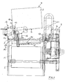
- the plan view of the overall device of Figure 1 illustrates a table 1, the inclusion of a part of a total stack removed sub-stack. 2 serves.
- the table 1 takes a drivable Feed roller 3 on.
- the table 1 is movably mounted in a frame 4, and admittedly, starting from the retracted position shown in FIG Direction of the arrow A into the total pile. This is in the page view the device shown in Figures 16 and 17.
- the frame 4 the table 1 is horizontal movably receives, vertically in a stand 8 movable.
- the means of power for Method of the table 1 and the frame 4 are not illustrated.
- the vertical one Movability of the table 1 allows this with respect to the current Align the height of the remainder of the stack from which a partial stack is to be removed.
- a support arm 11 is also movably mounted, which is parallel to the front Surface 9 of the stack 7 is arranged.
- the support arm 11 takes a holding gripper 12 and a movable in the longitudinal direction of the support arm 11 Verfahrgreifer 13 on.
- the Verfahrgreifer 13 is mounted in rails 14 of the support arm 11 and by means of a attached to the support arm 11 pneumatic cylinder 15 movable.
- the Verfahrgreifer 13 is designed as a gripper and has a Pliers base 16 on.
- the carrier connected to the support arm 11 64 of the traversing gripper is pivotable about a vertical axis in the support arm 11 mounted so that in a pivoted by about 10 ° end position of the support arm 11 and in position, but previously opened holding gripper 12th by shortening the carrier 64 of the partial stack 2 with its surface 9 in one to the conveyor roller 3 parallel position can be pivoted.
- auxiliary gripper 18 is provided which is vertically movable, and with the one between the partial stack 2 and the remaining stack 6 in the region of Side surface 19 inserted chip 20 can be taken.
- This chip is called formed rigid plate. According to the strength of each to be formed Partial stacks are a variety of chips inserted laterally in the total stack 7.
- FIG. 1 shows a unit 21 of supply lines for the units of FIGS Figure 1 described device, in two positions, a first Position with retracted table and a second position, the unit 21 would take in front table 1.
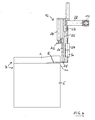
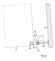
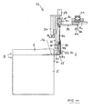
- Figures 2 and 3 illustrate the process step in which the holding gripper 12 by moving the support arm 11 in the open from the auxiliary gripper 18 Slot 5 enters, in a side view and a plan view, in the latter the stack is only indicated by dash-dotted lines.
- the auxiliary gripper 18 not shown, but only the from this raised chip 20. This is in the area of one through the corner 10 of the total stack 7 extending vertical edge of the total stack, thus inserted in a vertical corner region 65 of the total stack 7 in this and thus shares the partial stack 2 from the remaining stack 6.
- the auxiliary gripper 18 of the chip 20 rests on the remaining stack 6. If the chip 20 is raised by means of the auxiliary gripper 18, as he in particular is illustrated to figure 2, there is a lifting of the sub-stack 2 in the corner region 65th
- the support gripper 12 mounted in the support arm 11 has a pliers upper part 22, which is vertically movable in a vertical guide 23, wherein a pneumatic cylinder 24 for performing the movement of the tong upper 22 at this attacks.
- a pliers lower part 25 of the holding gripper 12 is fixed with a vertical Guide 23 having rail 26 connected in an opposite direction 27 is vertically displaceable. This countermotion is fixed with a carrier 28 connected, which engages the support arm 11.
- two pneumatic cylinders 29 and 30 are effective. Of the Pneumatic cylinder 29 is connected to the carrier 28 and the pneumatic cylinder 29 connected pneumatic cylinder 30 connected to the pliers lower part 25. These two pneumatic cylinders serve to raise and lower the lower part of the pliers 25 by moving the rail 26 in the counter guide 27.
- the holding gripper is 12 with his pliers lower part 25 in the means of the raised Chips 20 formed gap 5 in the area of the corner 10 of the total stack 7 retracted.
- the holding gripper 12 is open.
- the pliers base 16 is remote from the holding gripper 12 Page, the total stack 7 facing, with a about a Provided 90 ° angle extending rounding 31, wherein the pliers lower part 16, from the rounding 31 associated relatively sharp edge starting conically expanded.
- the total stack 7 facing area and the Holding gripper 12 remote from the area of the pliers lower part 16 is thus sword-shaped educated.
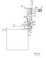
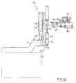
- FIG. 9 shows a side view of the traversing gripper 13, which with his pliers base 16 in between the partial stack 2 and the remaining stack 6 arranged extended gap 5 is retracted.
- a linear guide provided, which is a guide rail 40 which is attached to the carrier 11 is and cooperating with the guide rail 40 guide carriage 69 has.
- a bearing plate 39 is attached, the the Verfahrgreifer, in a manner to be described in more detail, to a pivotally receives vertical axis.
- the Verfahrgreifer 13 has a in one vertical guide 32 displaceable pliers upper part 33 on which a Pneumatic cylinder 34 attacks.
- the pliers lower part 16 is in a lockable Bearing 35 mounted, which is mounted on the one hand indirectly in springs 36, wherein a stop 38 by means of a pneumatic cylinder 37 indirectly on the Pliers lower part 16 acts, so that the pliers lower part 16 vertically downwards is firm and therefore can not influence in this direction.
- the top view according to FIG. 10 illustrates that illustrated in FIG Process step, the position of the pliers lower part 16 of the traversing gripper 13 and arranged next to this holding gripper 12th
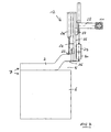
- FIG. 12 illustrates that simultaneously the closed holding gripper 12 by extending the Kobenstangen the cylinder 29 and 30 is lowered until its lower tongs part 25 slightly is located above the remaining stack 6. Then, as for the side view after the Figure 13 and the plan view of Figure 14 illustrates the Verfahrgreifer 13 across the total stack 7 with floating mounted pliers base 16.
- the table 1 with the feed roller 3 moves into the widened gap 5 between partial stacks 2 and residual stack 6, which is due to the lifting movement of the two grippers 12 and 13 extends over the entire width of the overall stack 7, a.
- the front End position of table 1 and conveyor roller 3 is shown in phantom in FIG Line illustrated.
- the support arm 11 on which the holding gripper 12 and the Verfahrgreifer 13 are attached, from the Conveyor roller 3 moved away, bringing the partial stack 2 of the grippers 12 and 13th is pulled on the table 1. Due to the pivotable mounting of the traversing gripper 13 in the support arm 11, the partial stack 2 when adopting the Table 1, at now open holding gripper 12, are pivoted, so that the partial stack 2, as illustrated for FIG.
- Figures 18 and 19 illustrate a modified design, which is a special Storage of the holding gripper concerns.
- the pliers lower part 25 and the Pliers upper part 22 of the holding gripper 12 exclusively vertically movable, such as it is the case in the embodiment of Figures 2 to 8, has a lifting of the sub-stack 2 with the result that the lowest layer of the sub-stack 2, relative to the area resting on the remainder stack 6 in the plane of Surface of the remaining stack 6, thus in the X and Y direction must move.
- the lower sheet layer of the sub-stack is thus not relative to shifted upper sheet layer of the remaining stack 6.
- FIGS 20 to 25 illustrate the structure of the Verfahrgreifers 13:
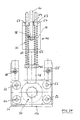
- FIG. 20 shows a side view of the representation of the travel gripper 13 in total.
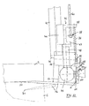
- FIG. 21 illustrates the lower region of the travel gripper. without pliers base 16 and without the connected thereto Casing.
- FIG. 22 shows a side view of the lower area of Verfahrgreifers 13 in the floating position of the pliers lower part 16, the between the partial stack 2 and the remaining stack 6 is introduced while FIG 23 in a corresponding side view of these parts the locked position of the Pliers lower part 16 illustrates, with between the pliers lower part 16 and the tongs upper part 33 clamped part stack 2.
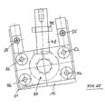
- Figure 24 illustrates a View B according to FIG. 23 of the lower region of the traveling gripper 13 chained pliers base 16, while Figure 25 is a corresponding view illustrated in floating position pliers lower part 16 illustrates.
- the vertical guide 32 This is illustrated in the vertical guide 32 by means of a guide carriage 43 movably mounted pliers lower part 33, by means of the pneumatic cylinder 34 is movable.
- the vertical guide 32 also takes a carriage 44, which serves to support the pliers lower part 16.
- the leadership 32 and a perpendicular thereto arranged bearing part 45 for the pliers lower part 16 form, based on the Verfahrgreifer 13, a non-movable unit.
- a bearing element 46 With the guide carriage 44, a bearing element 46 is connected in that has substantially the shape of a U, whose one leg 47 shortened is trained. At the shortened leg 47 is a vertically directed shaft 48th attached, which receives a ball 49 at the lower end. With this is a centering bolt 50 bolted.
- a connected to the pliers lower part 16 shared Housing 51 encloses the ball 49. Ball 49 and housing 51 form the Ball joint 35.
- the housing 51 In the housing 51 are guide shafts 52 for a centering plate 53 mounted, which by means of a housing 51 mounted in the pneumatic cylinder 54 in the direction of the housing 51 and away from it is movable. Is the piston rod 50 of the pneumatic cylinder 54 extended, contact bevels 66 bore of the centering plate 53 corresponding slopes 67 of the centering 50, whereby the housing 51 with pliers lower part 16 on the fixed Centering pin 50 is centered. As a result, the pliers base 16 is directed corresponding to the horizontal axis of the centering pin 50. This condition is shown in FIG.
- the pliers base can do accordingly the specification of the upper sheet layer of the rest of the stack and the lower sheet layer of the sub-stack 2 to be slightly inclined about this axis. By further centering means If desired, this tendency could also be eliminated. Is the By contrast, the centering plate 53 retracted, the housing 51 with pliers lower part can 16 move freely in all planes, as can be seen from the figure 22 is. Since the diameter of the hole 68 in the housing 51 is much larger is the diameter of the shaft 48, is the free movement of the pliers lower part 16 ensured. By a not illustrated adjustment The ball socket from below can be adjusted to the ease of movement of the joint become.
- each of the helical springs 36 passes through one of the guide rods 56.
- Another one central hole 59 of the leg 58 passes through a pull rod 60, which in the area its stopper 38 has its lower end. This is through a on the Tension rod plugged stop disk 61 formed, which rests on a nut 62, which screwed onto a threaded portion 63 of the tension rod 60 is.
- the pneumatic cylinder 37 serves for the vertical movement of the tension rod 60.
- the stop 38 When starting up the tension rod 60, the stop 38 contacts the leg 58 of the bearing element 36, so that the floating bearing of the bearing element 46 and thus of the pliers lower part 16 as a result of action of the springs 36 is repealed.
- the pliers lower part is thus in the vertical direction fixed down by means of the stop 38 and can thus counter-forces, by means of the tongs upper part 33 are exerted when gripping the partial stack 2, take up.
- FIG. 24 shows in the viewing direction B according to FIG. 23 the blocked position of the Ball 49 enclosing housing 51 and the pliers lower part 16, further the non-blocked state of the bearing element 46.
- Figure 25 shows, exclusively based on the area of storage of the ball 49, the unblockten State of the housing 51, at about the longitudinal axis of the centering pin 50th tilted housing 51.
- the illustrations of the pliers lower part 16 according to the Figures 22 and 25 illustrates clearly that the pliers base 16 a arbitrary orientation of the sheet layers in the stack can follow freely, due to floating support of the pliers lower part 16.
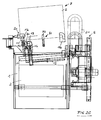
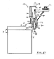
- Figure 26 illustrates the interaction of the support means 72, as a tongue is formed with the holding gripper 12 and the Verfahrgreifer 13.
- the tongue 72 is, as can be seen in addition to Figure 27, at right angles to a positioned rear bearing plate 73 and connected thereto.
- the bearing plate 73 receives a carriage 74 which is slidably mounted in a rail 75 is.
- the displacement takes place by means of a pneumatic cylinder 76, on the one hand on the carriage 74, on the other hand on a pivot arm 77 engages, with the Rail 75 is connected.
- This pivot arm 77 is in a horizontal arm 78 pivotally mounted about the axis 79, by means of a pneumatic cylinder 80, which engages the pivot arm 77 and the arm 78.
- the arm 78 is perpendicular to the pivoting plane of the pivot arm 77, in the support arm 11 via not slidably mounted adjusting means shown in detail.
- the tongue 72 can be in between the Partial stack 2 and the remaining stack 6 formed gap 5 retract and the tongue 72 raise and lower by means of the pneumatic cylinder 76.
- the operation of the device using the proppant or The tongue 72 is preferably as follows:
- the holding gripper 12 holds the partial stack 2.
- the Verfahrgreifer 13 is floating until about the middle of the total stack 7 method, based on the front surface.
- the pivoted support means 72 follows the Verfahrgreifer 13, by the arm 78 is moved in the longitudinal direction of the support arm 11. Then the Verfahrgreifer 13 is closed and raises the partial stack 2.
- the Swivel device pivots the tongue 72 in the gap 5. The Verfahrgreifer 13 lowers again and floats on the remaining stack 6.
- the partial stack 2 puts as a result on the tongue 72. Then the floating position traversing gripper 13 further moved through the total stack 7, to the end of the stack, which faces away from the holding gripper 12.
- Figure 26 shows the pivoting device 81 with the tongue 72 on the one hand in the swung out, left starting position, on the other hand in their pivoted central position, also the traversing gripper 13 before retracting into the gap 5 and when reaching its right end position.
- no support means 72 is provided, so that this embodiment corresponds to that of Figures 1 and 2.
- the object of the additional support element according to the figures 26 and 27 assumes in this further embodiment of the holding gripper 12, the at raised chip 20, based on the direction of travel of Verfahrgreifers 13th moves into a position behind the moving gripper 13 located in the middle position, and then the traversing gripper from this middle position on until the chip 20 remote from the end of the total stack 7 moves.
- the Partial stack is then over the closed in the middle position Holding gripper 12 and located in the final position traversing 13th raised and additionally at the end facing away from the Verfahrgreifer 13 of the stack 7 carried by the chip 20.
- This situation is illustrated in FIG. It can then the table 1 with the feed roller 3 in the open Slot 2 between partial stack 2 and rest stack 6 retract to the partial stack. 2 to take over.
Landscapes
- Engineering & Computer Science (AREA)
- Mechanical Engineering (AREA)
- Pile Receivers (AREA)
Priority Applications (1)
| Application Number | Priority Date | Filing Date | Title |
|---|---|---|---|
| EP04003972A EP1566355A1 (fr) | 2004-02-21 | 2004-02-21 | Procédé et dispositif pour diviser une pile de feuilles |
Applications Claiming Priority (1)
| Application Number | Priority Date | Filing Date | Title |
|---|---|---|---|
| EP04003972A EP1566355A1 (fr) | 2004-02-21 | 2004-02-21 | Procédé et dispositif pour diviser une pile de feuilles |
Publications (1)
| Publication Number | Publication Date |
|---|---|
| EP1566355A1 true EP1566355A1 (fr) | 2005-08-24 |
Family
ID=34707359
Family Applications (1)
| Application Number | Title | Priority Date | Filing Date |
|---|---|---|---|
| EP04003972A Withdrawn EP1566355A1 (fr) | 2004-02-21 | 2004-02-21 | Procédé et dispositif pour diviser une pile de feuilles |
Country Status (1)
| Country | Link |
|---|---|
| EP (1) | EP1566355A1 (fr) |
Cited By (4)
| Publication number | Priority date | Publication date | Assignee | Title |
|---|---|---|---|---|
| EP2251285A1 (fr) * | 2009-05-11 | 2010-11-17 | Adolf Mohr Maschinenfabrik GmbH & Co. KG | Dispositif destiné à enlever une pile partielle de produits en forme de feuilles à partir d'une pile entière |
| DE102010056593B4 (de) * | 2010-06-25 | 2013-01-03 | Baumann Maschinenbau Solms Gmbh & Co. Kg | Verfahren zur Ermittlung einer Ortsposition einer Seitenkante eines Materialstapels |
| DE102010017593B4 (de) * | 2010-06-25 | 2013-01-03 | Baumann Maschinenbau Solms Gmbh & Co. Kg | Verfahren und Anordnung zum Aufnehmen eines Teilstapels einer abgezählten Anzahl von Materialbögen von einem Materialstapel |
| CN112623842A (zh) * | 2020-12-05 | 2021-04-09 | 东莞市悦声纸业有限公司 | 一种叠置纸片堆推料输送机构 |
Citations (3)
| Publication number | Priority date | Publication date | Assignee | Title |
|---|---|---|---|---|
| US5417543A (en) * | 1992-07-10 | 1995-05-23 | Focke & Co. (Gmbh & Co.) | Process and apparatus for handling blank stacks |
| DE19955878A1 (de) * | 1999-11-21 | 2001-05-23 | Kerber Guido | Verfahren und Einrichtung zum Aufteilen von Blattstapeln |
| EP1116677A2 (fr) * | 2000-01-13 | 2001-07-18 | Baumann Maschinenbau Solms GmbH & Co. KG | Dispositif pour le transport et le positionnement de rames de matériau en feuille empilé |
-
2004
- 2004-02-21 EP EP04003972A patent/EP1566355A1/fr not_active Withdrawn
Patent Citations (3)
| Publication number | Priority date | Publication date | Assignee | Title |
|---|---|---|---|---|
| US5417543A (en) * | 1992-07-10 | 1995-05-23 | Focke & Co. (Gmbh & Co.) | Process and apparatus for handling blank stacks |
| DE19955878A1 (de) * | 1999-11-21 | 2001-05-23 | Kerber Guido | Verfahren und Einrichtung zum Aufteilen von Blattstapeln |
| EP1116677A2 (fr) * | 2000-01-13 | 2001-07-18 | Baumann Maschinenbau Solms GmbH & Co. KG | Dispositif pour le transport et le positionnement de rames de matériau en feuille empilé |
Cited By (4)
| Publication number | Priority date | Publication date | Assignee | Title |
|---|---|---|---|---|
| EP2251285A1 (fr) * | 2009-05-11 | 2010-11-17 | Adolf Mohr Maschinenfabrik GmbH & Co. KG | Dispositif destiné à enlever une pile partielle de produits en forme de feuilles à partir d'une pile entière |
| DE102010056593B4 (de) * | 2010-06-25 | 2013-01-03 | Baumann Maschinenbau Solms Gmbh & Co. Kg | Verfahren zur Ermittlung einer Ortsposition einer Seitenkante eines Materialstapels |
| DE102010017593B4 (de) * | 2010-06-25 | 2013-01-03 | Baumann Maschinenbau Solms Gmbh & Co. Kg | Verfahren und Anordnung zum Aufnehmen eines Teilstapels einer abgezählten Anzahl von Materialbögen von einem Materialstapel |
| CN112623842A (zh) * | 2020-12-05 | 2021-04-09 | 东莞市悦声纸业有限公司 | 一种叠置纸片堆推料输送机构 |
Similar Documents
| Publication | Publication Date | Title |
|---|---|---|
| DE69100158T2 (de) | Greif- und Übertragungszange. | |
| EP0453933B1 (fr) | Dispositif pour couper des produits lamellaires empilés | |
| DE69317051T2 (de) | Speicher für bögen mit zurückziehbarer rampe | |
| EP0429941B1 (fr) | Dispositif pour couper des feuilles empilées | |
| DE2407941A1 (de) | Verfahren und vorrichtung zum handhaben von stoffstuecken | |
| DE3524511A1 (de) | Papierblatt-handhabungsvorrichtung | |
| CH697146A5 (de) | Greifvorrichtung zur Handhabung von Wafern. | |
| EP1767477A1 (fr) | Procédé et appareil pour l'insertion d'articles plats dans une machine de traitement | |
| EP1484270A2 (fr) | Dispositif et procédé de traitement ultérieur d'une rame résiduelle avec ménagement et sans déchets | |
| DE19722295C2 (de) | Vorrichtung zum Ablegen von Blättern | |
| EP0936035B1 (fr) | Méthode pour régler la position d'une lame lors du changement de lame, ainsi qu'une machine équipée de moyens pour changer de lame | |
| EP3227069B1 (fr) | Installation de division de plaques pour diviser des pièces en forme de plaque et procédé pour faire fonctionner celle-ci | |
| DE2847083B2 (de) | Vorrichtung zum Vereinzeln gewebter, gestickter oder vliesartiger Stoff stücke von einem Stapel | |
| DE102013206159B4 (de) | Plattenaufteilanlage | |
| EP3398742B1 (fr) | Dispositif de sciage pour couper des pièces en forme de plaque | |
| EP1566355A1 (fr) | Procédé et dispositif pour diviser une pile de feuilles | |
| EP0751086A2 (fr) | Dispositif pour extraire les inclusions d'air de piles de papier | |
| EP1083138A2 (fr) | Dispositif pour séparer des sacs vides | |
| DE3933625C1 (fr) | ||
| EP2123412A1 (fr) | Machine de coupe destinée à la coupe de articles empilés, en forme de feuilles, et procédé | |
| DE3915284C2 (fr) | ||
| CH617409A5 (en) | System for jogging material sheets to form a stack | |
| CH621287A5 (en) | Machine for breaking out cutouts | |
| DD220005A1 (de) | Beschickungsvorrichtung fuer in fliesslinie angeordnete naehautomaten | |
| DE102010016938B4 (de) | Vorrichtung und Verfahren zum Abnehmen eines Teilstapels von einem Blätterstapel |
Legal Events
| Date | Code | Title | Description |
|---|---|---|---|
| PUAI | Public reference made under article 153(3) epc to a published international application that has entered the european phase |
Free format text: ORIGINAL CODE: 0009012 |
|
| 17P | Request for examination filed |
Effective date: 20050308 |
|
| AK | Designated contracting states |
Kind code of ref document: A1 Designated state(s): AT BE BG CH CY CZ DE DK EE ES FI FR GB GR HU IE IT LI LU MC NL PT RO SE SI SK TR |
|
| AX | Request for extension of the european patent |
Extension state: AL LT LV MK |
|
| AKX | Designation fees paid |
Designated state(s): AT BE BG CH CY CZ DE DK EE ES FI FR GB GR HU IE IT LI LU MC NL PT RO SE SI SK TR |
|
| STAA | Information on the status of an ep patent application or granted ep patent |
Free format text: STATUS: THE APPLICATION HAS BEEN WITHDRAWN |
|
| 18W | Application withdrawn |
Effective date: 20080211 |