EP1566492B1 - Küchenspüle mit Restebecken - Google Patents
Küchenspüle mit Restebecken Download PDFInfo
- Publication number
- EP1566492B1 EP1566492B1 EP05002462A EP05002462A EP1566492B1 EP 1566492 B1 EP1566492 B1 EP 1566492B1 EP 05002462 A EP05002462 A EP 05002462A EP 05002462 A EP05002462 A EP 05002462A EP 1566492 B1 EP1566492 B1 EP 1566492B1
- Authority
- EP
- European Patent Office
- Prior art keywords
- kitchen sink
- edge region
- region
- cup
- receiving trough
- Prior art date
- Legal status (The legal status is an assumption and is not a legal conclusion. Google has not performed a legal analysis and makes no representation as to the accuracy of the status listed.)
- Expired - Lifetime
Links
Images


Classifications
-
- E—FIXED CONSTRUCTIONS
- E03—WATER SUPPLY; SEWERAGE
- E03C—DOMESTIC PLUMBING INSTALLATIONS FOR FRESH WATER OR WASTE WATER; SINKS
- E03C1/00—Domestic plumbing installations for fresh water or waste water; Sinks
- E03C1/12—Plumbing installations for waste water; Basins or fountains connected thereto; Sinks
- E03C1/18—Sinks, whether or not connected to the waste-pipe
Definitions
- the invention relates to a kitchen sink, preferably for installation in a kitchen worktop, with at least one basin, which is surrounded by a mirror, wherein in the mirror a receiving trough is formed, which is formed in its bordering the mirror edge region substantially spherical segment-like concave.
- a sink of this kind is known, for example from the DE-U 299 03 012 ,
- the receiving trough in this known sink is a total of spherical segment or spherical cap-like concave and formed so that a hemispherical residual shell is to be used in it.
- Object of the present invention is therefore to provide a kitchen sink as indicated above in such a way that the receiving trough is safe to combine with inserts of various kinds.
- This object is achieved in that the surrounded by the edge region of the central region of the receiving trough is pot-shaped, that is, in the receiving trough with substantially vertical walls is set down discontinued.
- This design has the advantage that now essentially spherical bowls, sieves, colanders of various diameters can be placed in the receiving trough. These are then based either on the substantially spherical segment-like curved edge region or on the ring-shaped in principle annular transition from this edge region to the cup-shaped central region. In particular, the feet which are usually present on such bowls etc. can also come to lie in the pot-like middle region, so that there is a line-shaped support between sink and bowl, etc.
- a buffer element can also be provided at the transition from the edge region to the cup-shaped middle region in order to avoid scratching either the bowls, screens, strainer, etc. used or else a corresponding scratching of the kitchen sink in this transition region.
- This buffer element may be both a ring encircling the central cup-shaped region, which ring is made in particular of plastic, and also buffers provided only in segments.
- the bottom of the middle pot-like area is preferably still a drain to integrate, resulting in a useful residual pool.
- a particularly preferred element for insertion into the receiving trough according to the invention is a salad spinner. This can be offset by means of a cable or a befindliches on the cover of the spinner gear transmission in high speeds, in which case possibly occurring imbalances can be absorbed by the receiving trough.
- FIG. 1 can be seen a kitchen sink, which consists of stainless steel in the example shown here. But it is also possible to make them from ceramic or plastic (possibly with appropriate admixtures).
- the kitchen sink has a peripheral edge 2, with which it rests on a cutting edge of a kitchen worktop 3.
- the kitchen sink shown here has a deep basin 4, which is surrounded by a substantially horizontally formed mirror 5.
- This mirror is in the example shown here in the left in the drawing area of the sink in a drainer 6 over.
- a receiving recess 7, which is essentially circular in plan view, is formed between the basin 4 and the draining surface 5.
- This receptacle is at her on the mirror 5 adjacent edge region 8 spherical segment convex curved.
- edge region 8 Surrounded by the edge region 8 middle region 9 of the receiving trough 7 is pot-shaped with a substantially vertical wall 10 which circulates in a circle around a substantially horizontal bottom 11.
- drain 12 In the bottom 11 a (not dargesteller more) drain 12 is present.
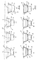
- FIG. 2 various bowls are shown, which are inserted into a receiving trough 7, which has a central region, which is designed pot-shaped as described above.
- a receiving trough 7 which has a central region, which is designed pot-shaped as described above.
- the outer wall of the bowl 13 is flat on the edge region 8 of the receiving trough 7 at.
- the existing in the bowl peripheral base 14 comes to rest in the central region 9 of the receiving trough 7, so that it is not hindered by the flat contact the outside of the bowl 8 to the edge region 8.
- bowls 15 are used with smaller radii than the ball radius of the edge region 8 in the receiving troughs 7. It can be seen that the bowls 15 with their outer walls touch the edge region 8 of the receiving troughs 7 only more or less linear. But it is still a relatively tip over insertion of the bowls 15 guaranteed in the receiving troughs 7.
- the feet 14 of the bowls 15 come to rest in the cup-shaped, lowered central region 9 of the receiving troughs 7, so that stabilization takes place here.
- FIG. 2d Another example is still in the Figure 2d shown.
- a hemispherical bowl 16 which has a smaller radius than the radius of the spherical edge portion 8 of the receiving trough 7, when inserted into the receiving trough in a linear system.
- This linear system is located at the junction 17 of the cup-like, lowered middle area 9 to the edge region 8, that is approximately in the area where the wall 10 merges into the edge region 8. Since the bowl 16 receives a total of a circular support at the junction 17, it is kept stable in the receiving trough 7.
- FIGS. 3a-d are bowls that are essentially similar to the bowls in the bowls FIGS. 2a-d , used in the receiving troughs 7.
- a buffer member 18 which covers the transition 17 and so a metallic contact between the usually made of stainless steel bowls 13 to 16 with the edge region 8 or the transition 17 at prevents the metallic sink.
- the buffer element 18, which consists of a suitable plastic, is provided on its inside with a through hole 19, in which the feet 14 of the bowls engage, so as to stabilize the bowls in their position.
- the buffer element has a shape adapted to the shape of the transition 17 contour.
- a strainer 20 can also be inserted into the receiving trough 7, so that it comes into contact with the edge region 8.
- the liquid exiting through holes 21 at the bottom of the sieve can drop directly into the cup-like lowered central region 9 and can be removed from there either via the drain 12 or else be collected via a collecting bowl inserted into this cup-shaped lowered central region. (Last is not shown.)
- a spin basket 22 is inserted into the wire 20, which is seated on a molded into the screen pin 23 and is offset by a pulling mechanism 24 in rotation.
- befind Anlagen washed salad is thereby spun dry and the running water occurs at the lower end of the wire 20 through the holes 21 in the pot-like lowered central region 9 of the receiving trough. 7
- the screen 20 shown here has a ring on the bottom of rotating base 25. About this it can also be supported against the wall 10, which may be intercepted occurring during spin unbalance.
Landscapes
- Engineering & Computer Science (AREA)
- Environmental & Geological Engineering (AREA)
- Health & Medical Sciences (AREA)
- Life Sciences & Earth Sciences (AREA)
- Hydrology & Water Resources (AREA)
- Public Health (AREA)
- Water Supply & Treatment (AREA)
- Sink And Installation For Waste Water (AREA)
- Combinations Of Kitchen Furniture (AREA)
- Food-Manufacturing Devices (AREA)
Description
- Die Erfindung betrifft eine Küchenspüle, vorzugsweise zum Einbau in eine Küchenarbeitsplatte, mit wenigstens einem Becken, das von einem Spiegel umgeben ist, wobei in den Spiegel eine Aufnahmemulde eingeformt ist, die in ihrem an den Spiegel angrenzenden Randbereich im wesentlichen kugelsegmentartig konkav gewölbt ausgebildet ist.
- Eine Spüle dieser Art ist beispielsweise bekannt aus der
DE-U 299 03 012 . Die Aufnahmemulde bei dieser vorbekannten Spüle ist insgesamt kugelsegment- bzw. kugelkappenartig konkav gewölbt und so ausgebildet, dass in ihr eine halbkugelige Resteschale einzusetzen ist. - Von Benutzern derartiger Küchenspülen wird dabei als nachteilig empfunden, dass nur speziell vorgesehene Resteschalen zu verwenden sind, die in ihrer Form genau an die kugelkappenartige Form der Abtropfmulde angepasst sind. Andere Schüsseln, Siebe, Seiher o. ä., die in gut ausgerüsteten Küchen üblicherweise vorhanden sind, die kugelig ausgebildet sind aber einen anderen Kugeldurchmesser haben als die Aufnahmemulde bzw. die ihr zugeordnete Resteschale sind in der Aufnahmemulde nicht einzusetzen: Insbesondere, wenn der Durchmesser solcher anderer Elemente kleiner ist als der der Aufnahmemulde sind diese Elemente nicht zu fixieren und tendieren daher zum Kippen.
- Aufgabe der vorliegenden Erfindung ist es daher, eine Küchenspüle wie oben angegeben derart weiterzubilden, dass die Aufnahmemulde mit Einsätzen der unterschiedlichsten Art sicher zu kombinieren ist.
- Diese Aufgabe wird erfindungsgemäß dadurch gelöst, dass der vom Randbereich umgebene mittlere Bereich der Aufnahmemulde topfartig ausgebildet ist, das heißt, in die Aufnahmemulde mit im Wesentlichen senkrechten Wänden nach unten abgesetzt ausgeformt ist.
- Diese Ausführung hat den Vorteil, dass jetzt im Wesentlichen kugelförmige Schüsseln, Siebe, Seiher unterschiedlichster Durchmesser in die Aufnahmemulde gesetzt werden können. Diese stützen sich dann entweder am im Wesentlichen kugelsegmentartig gewölbten Randbereich ab oder aber an dem im Prinzip ringförmig ausgebildeten Übergang von diesem Randbereich zum topfartigen mittleren Bereich. Insbesondere können die an derartigen Schüsseln etc. üblicherweise vorhandenen Füße dabei auch in dem topfartigen Mittelbereich zu liegen kommen, so dass eine linienförmige Auflage zwischen Spüle und Schüssel etc. vorliegt.
- Vorteilhafterweise kann dabei an dem Übergang vom Randbereich zum topfartigen mittleren Bereich auch ein Pufferelement vorgesehen werden, um ein Verkratzen entweder der eingesetzten Schüsseln, Siebe, Seiher etc. zu vermeiden oder aber auch ein entsprechendes Verkratzen der Küchenspüle in diesem Übergangsbereich.
- Bei diesem Pufferelement kann es sich sowohl um einen um den mittleren topfartig abgesenkten Bereich umlaufenden Ring handeln, der insbesondere aus Kunststoff besteht, als auch um lediglich segmentartig vorgesehene Puffer.
- In den Boden des mittleren topfartigen Bereiches ist vorzugsweise noch ein Ablauf zu integrieren, wodurch sich ein nützliches Restebecken ergibt.
- Es ist weiterhin möglich, in den topfartigen Bereich eine an diesen formmäßig angepasste Schale einzusetzen. Damit besteht auch die Möglichkeit, von einem darüber sitzenden Sieb oder Seiher ablaufende Säfte o. ä. aufzufangen.
- Alternativ besteht aber auch die Möglichkeit, eine derartige Schale als einzusetzenden Restesieb auszubilden mit entsprechenden Lochung, so dass in die als Restebecken fungierende Aufnahmemulde kommenden Küchenabfällen o. ä in diesem Restesieb zu liegen kommen, abtropfen können und dann in einem relativ trockenen Zustand zu entsorgen sind, wobei das abtropfende Wasser durch die genannten Lochungen (Öffnungen) abfließt.
- Bei einem besonders bevorzugten Element zum Einsetzen in die erfindungsgemäße Aufnahmemulde handelt es sich um eine Salatschleuder. Diese kann über einen Seilzug oder über ein an dem Deckel der Schleuder befindliches Zahnradgetriebe in hohe Drehzahlen versetzt werden, wobei dann bei ihr eventuell auftretende Unwuchten durch die Aufnahmemulde aufgefangen werden können.
- Weitere Vorteile und Merkmale der Erfindung ergeben sich aus der nachfolgenden Beschreibung von Ausführungsbeispielen. Dabei zeigt
- Figur 1
- den Schnitt durch eine erfindungsgemäße Küchenspüle
- Figur 2 a - d
- Aufnahmemulden mit kugelsegmentartigem äußeren Randbe-reich und topfartig ausgebildetem nach unten abgesenkten mittleren Bereich mit aufgesetzten Schüsseln unterschiedlicher Durchmesser;
- Figur 3 a - d
- Aufnahmemulden gemäß
Figur 2 mit einem zusätzlich vorgesehenem Pufferelement; - Figur 4
- eine Aufnahmemulde mit eingesetzter Salatschleuder.
- In der
Figur 1 erkennt man eine Küchenspüle, die im hier dargestellten Beispiel aus Edelstahl besteht. Es ist aber auch möglich, sie aus Keramik oder aus Kunststoff (ggf. auch mit entsprechenden Beimischungen) herzustellen. Die Küchenspüle weist einen umlaufenden Rand 2 auf, mit dem sie auf einen Ausschnittrand einer Küchenarbeitsplatte 3 aufliegt. - Die hier dargestellte Küchenspüle weist ein tiefes Becken 4 auf, das von einem im Wesentlichen horizontal ausgebildeten Spiegel 5 umgeben ist. Dieser Spiegel geht im hier dargestellten Beispiel im in der Zeichnung links liegenden Bereich der Spüle in eine Abtropffläche 6 über. Im hier dargestellten Beispiel ist zwischen dem Becken 4 und der Abtropffläche 5 eine in der Aufsicht im Wesentlichen kreisrunde Aufnahmemulde 7 eingeformt. Diese Aufnahmemulde ist an ihrem an den Spiegel 5 angrenzenden Randbereich 8 kugelsegmentartig konvex gewölbt.
- Der vom Randbereich 8 umgebene mittlere Bereich 9 der Aufnahmemulde 7 ist topfartig ausgebildet mit einer im Wesentlichen vertikalen Wand 10, die kreisförmig um einen im Wesentlichen horizontalen Boden 11 umläuft.
- Im Boden 11 ist ein (nicht näher dargesteller) Abfluss 12 vorhanden.
- In der
Figur 2 sind verschiedene Schüsseln dargestellt, die in eine Aufnahmemulde 7 eingesetzt sind, die einen mittleren Bereich aufweist, der wie oben beschrieben topfartig abgesenkt ausgebildet ist. Bei einer wie in derFigur 2a vorgesehenen Schüssel 13, die einen Durchmesser entsprechend dem Kugeldurchmesser des Randbereiches 8 aufweist, liegt die Außenwand der Schüssel 13 flächig am Randbereich 8 der Aufnahmemulde 7 an. Der bei der Schüssel vorhandene umlaufende Standfuß 14 kommt in dem mittleren Bereich 9 der Aufnahmemulde 7 zu liegen, so dass durch ihn die flächige Anlage der Außenseite der Schüssel 8 an den Randbereich 8 nicht behindert wird. - In den
Figuren 2b und 2c sind Schüsseln 15 mit kleineren Radien als der Kugelradius des Randbereiches 8 in die Aufnahmemulden 7 eingesetzt. Man erkennt, dass die Schüsseln 15 mit ihren Außenwänden den Randbereich 8 der Aufnahmemulden 7 nur mehr oder weniger linienförmig berühren. Es ist aber trotzdem ein relativ kippsicheres Einsetzen der Schüsseln 15 in die Aufnahmemulden 7 gewährleistet. - Auch in diesen Beispielen kommen dabei die Standfüße 14 der Schüsseln 15 in den topfartigen, abgesenkten Mittelbereich 9 der Aufnahmemulden 7 zu liegen, so dass hier eine Stabilisierung erfolgt.
- Ein weiteres Beispiel ist dann noch in der
Figur 2d dargestellt. Auch hier kommt eine halbkugelförmige Schüssel 16, die einen kleineren Radius hat als der Radius des kugelförmigen Randbereiches 8 der Aufnahmemulde 7, beim Einsetzen in die Aufnahmemulde in eine linienförmige Anlage. Diese linienförmige Anlage befindet sich dabei am Übergang 17 vom topfartigen, abgesenkten mittleren Bereich 9 zum Randbereich 8, also in etwa in dem Bereich, wo die Wand 10 in den Randbereich 8 übergeht. Da die Schüssel 16 dabei insgesamt auch eine kreisförmige Abstützung am Übergang 17 erhält, wird sie in der Aufnahmemulde 7 stabil gehalten. - In den
Figuren 3a - d sind Schüsseln, die im Wesentlichen gleichartig sind mit den Schüsseln in denFiguren 2a - d , in die Aufnahmemulden 7 eingesetzt. In den in derFigur 3 dargestellten Beispielen findet sich dabei aber am Übergang 17 von den Wänden 10 zum Randbereich 8 ein Pufferelement 18, das den Übergang 17 überdeckt und so einen metallischen Kontakt zwischen den üblicherweise aus Edelstahl bestehenden Schüsseln 13 bis 16 mit dem Randbereich 8 oder aber dem Übergang 17 an der metallischen Spüle verhindert. Das Pufferelement 18, das aus einem geeigneten Kunststoff besteht, ist dabei auf seiner Innenseite mit einem Durchgangsloch 19 versehen, in das die Standfüße 14 der Schüsseln eingreifen, um so die Schüsseln in ihrer Lage zu stabilisieren. - Auf der Außenseite hat das Pufferelement eine an die Form des Überganges 17 angepasste Kontur.
- Anstelle einer Schüssel, wie in den
Figuren 2 und 3 dargestellt, kann auch ein Sieb 20 in die Aufnahmemulde 7 eingesetzt werden, so dass es mit dem Randbereich 8 in Anlage kommt. Die durch Löcher 21 am Boden des Siebes austretende Flüssigkeit kann dabei direkt in den topfartig abgesenkten mittleren Bereich 9 tropfen und von dort entweder über den Ablauf 12 abgeführt oder aber über eine in diesen topfartig abgesenkten mittleren Bereich eingesetzte Auffangschale aufgefangen werden. (Letzte ist nicht dargestellt.) - Im in der
Figur 4 dargestellten Beispiel ist in das Sieb 20 ein Schleuderkorb 22 eingesetzt, der auf einem in das Sieb eingeformten Stift 23 sitzt und über einen Zugmechanismus 24 in Rotation zu versetzten ist. In dem Schleuderkorb 22 befindlicher gewaschener Salat wird dabei trocken geschleudert und das dabei ablaufende Wasser tritt am unteren Ende des Siebes 20 durch die Löcher 21 in den topfartig abgesenkten mittleren Bereich 9 der Aufnahmemulde 7. - Auch das hier dargestellte Sieb 20 hat einen ringförmig am unteren Bereich umlaufenden Standfuß 25. Über diesen kann es sich auch gegen die Wand 10 abstützen, womit eventuell beim Schleudern auftretende Unwuchten abgefangen werden können.
Claims (6)
- Küchenspüle (1) mit wenigstens einem Becken (4), das von einem Spiegel (5) umgeben ist, wobei in den Spiegel (5) eine Aufnahmemulde (7) eingeformt ist, die in ihrem an den Spiegel (5) angrenzenden Randbereich (8) im Wesentlichen kugelsegmentartig gewölbt ist,
dadurch gekennzeichnet,
dass der vom Randbereich (8) umgebene mittlere Bereich (9) der Aufnahmemulde (7) topfartig ausgebildet ist. - Küchenspüle gemäß Anspruch 1,
dadurch gekennzeichnet,
dass am Boden (11) des topfartigen mittleren Bereiches (9) ein Ablauf (12) ist. - Küchenspüle gemäß Anspruch 1,
dadurch gekennzeichnet,
dass am Übergang (17) vom Randbereich (8) zum topfartigen mittleren Bereich (9) ein Pufferelement (18) vorgesehen ist. - Küchenspüle gemäß Anspruch 1,
dadurch gekennzeichnet,
dass auf die Aufnahmemulde (7) ein Sieb (20) aufsetzbar ist. - Küchenspüle gemäß Anspruch 4,
dadurch gekennzeichnet,
dass das Sieb eine (20) Schleuder (22) enthält. - Küchenspüle gemäß Anspruch 5,
dadurch gekennzeichnet,
dass das Sieb (20) einen Standfuß (25) aufweist, über den es sich gegen beim Schleudern auftretende Unwuchten am topfartig abgesenkten Bereich (9) abstützt.
Applications Claiming Priority (2)
| Application Number | Priority Date | Filing Date | Title |
|---|---|---|---|
| DE102004007820A DE102004007820A1 (de) | 2004-02-18 | 2004-02-18 | Küchenspüle mit Restebecken |
| DE102004007820 | 2004-02-18 |
Publications (3)
| Publication Number | Publication Date |
|---|---|
| EP1566492A2 EP1566492A2 (de) | 2005-08-24 |
| EP1566492A3 EP1566492A3 (de) | 2006-07-26 |
| EP1566492B1 true EP1566492B1 (de) | 2008-08-27 |
Family
ID=34706830
Family Applications (1)
| Application Number | Title | Priority Date | Filing Date |
|---|---|---|---|
| EP05002462A Expired - Lifetime EP1566492B1 (de) | 2004-02-18 | 2005-02-05 | Küchenspüle mit Restebecken |
Country Status (4)
| Country | Link |
|---|---|
| EP (1) | EP1566492B1 (de) |
| CN (1) | CN1757836A (de) |
| AT (1) | ATE406483T1 (de) |
| DE (2) | DE102004007820A1 (de) |
Families Citing this family (1)
| Publication number | Priority date | Publication date | Assignee | Title |
|---|---|---|---|---|
| DE102010024571B4 (de) * | 2010-06-22 | 2012-07-12 | Franke Technology And Trademark Ltd. | Spüle mit Vertiefung zur Aufnahme von Reinigungsgeräten |
Family Cites Families (9)
| Publication number | Priority date | Publication date | Assignee | Title |
|---|---|---|---|---|
| US1605919A (en) * | 1925-04-03 | 1926-11-09 | Chicago Hardware Foundry Compa | Drain board and cover for dishwashers, etc. |
| GB602264A (en) * | 1945-07-12 | 1948-05-24 | Norman Greenwood Best | Improvements in or relating to hollow-ware |
| DE7830240U1 (de) * | 1978-10-11 | 1980-03-20 | Blanc Gmbh & Co, 7519 Oberderdingen | Einbauspuele |
| EP0038898B1 (de) * | 1980-04-21 | 1984-01-18 | Georgette Beduin | Spülbecken |
| DE3421821A1 (de) * | 1984-06-13 | 1985-12-19 | Villeroy & Boch Keramische Werke Kg, 6642 Mettlach | Kuechenspuele |
| DE29807541U1 (de) * | 1998-04-29 | 1998-07-23 | Schock & Co GmbH, 73614 Schorndorf | Spüle |
| DE29903012U1 (de) * | 1999-02-19 | 1999-05-06 | Rieber GmbH & Co., 72770 Reutlingen | Einbauspüle |
| DE10065057A1 (de) * | 2000-12-27 | 2002-07-04 | Niro Plan Ag Zug | Küchenspüle mit einem Zusatzbecken |
| DE10141993B4 (de) * | 2001-08-28 | 2005-06-30 | Max Maier | Becken für eine Spüle, insbesondere für eine Rundspüle |
-
2004
- 2004-02-18 DE DE102004007820A patent/DE102004007820A1/de not_active Withdrawn
-
2005
- 2005-02-05 DE DE502005005162T patent/DE502005005162D1/de not_active Expired - Lifetime
- 2005-02-05 EP EP05002462A patent/EP1566492B1/de not_active Expired - Lifetime
- 2005-02-05 AT AT05002462T patent/ATE406483T1/de not_active IP Right Cessation
- 2005-02-18 CN CN200510067641.XA patent/CN1757836A/zh active Pending
Also Published As
| Publication number | Publication date |
|---|---|
| ATE406483T1 (de) | 2008-09-15 |
| CN1757836A (zh) | 2006-04-12 |
| DE102004007820A1 (de) | 2005-09-08 |
| EP1566492A2 (de) | 2005-08-24 |
| EP1566492A3 (de) | 2006-07-26 |
| DE502005005162D1 (de) | 2008-10-09 |
Similar Documents
| Publication | Publication Date | Title |
|---|---|---|
| DE4106212A1 (de) | Kuecheneinheit | |
| DE102012107762B3 (de) | Feinfilterstruktur | |
| DE202007019150U1 (de) | Zusammenlegbare Schüssel und Sieb | |
| DE202017105060U1 (de) | Multifunktionale Teekanne mit Filtereinsatz und herausfallsicherem Kannendeckel | |
| US4806241A (en) | Overflow lint strainer | |
| DE212007000014U1 (de) | Zusammenklappbares Abtropfsieb und Schüssel | |
| WO2019020403A1 (de) | Geruchsverschlussvorichtung für sanitärvorrichtungen, insbesondere urinale | |
| DE69702971T2 (de) | Vorrichtung zum abführen des regenwassers von dächern | |
| EP1219229B1 (de) | Küchenspüle mit einem Zusatzbecken | |
| DE3730072A1 (de) | Zubehoer-set fuer kuechenspuelen | |
| DE3137651A1 (de) | Auslauf fuer einen getraenkebereiter | |
| EP2258905B1 (de) | Ablauf, insbesondere für sanitäre Einrichtungen | |
| EP1272072B1 (de) | Saftzentrifuge | |
| EP1566492A2 (de) | Küchenspüle mit Restebecken | |
| EP1813731A2 (de) | Küchenspüle, insbesondere für Haushaltszwecke | |
| EP3839158B1 (de) | Duschtasse | |
| DE3126630A1 (de) | Zentrifugenkorb | |
| DE202007019491U1 (de) | Trinkbrunnen | |
| DE10220996B4 (de) | Stopfen für ein Abflussrohr | |
| KR20200103449A (ko) | 막힘 방지 기능이 부여된 배수구용 거름망 구조 | |
| DE202021100337U1 (de) | Flüssigkeitsauffangbehälter für ein Küchengerät | |
| EP3825478A1 (de) | Abflusssieb für eine ablaufleitung | |
| DE102021124947A1 (de) | Ergänzungsset für ein Multifunktionsküchengerät, ein Multifunktionsküchengerät und ein Verfahren zum Bearbeiten von Schneidgut | |
| DE20117076U1 (de) | Spritzschutzabdeckung | |
| KR200282578Y1 (ko) | 하수구 마개의 배수구 구조 |
Legal Events
| Date | Code | Title | Description |
|---|---|---|---|
| PUAI | Public reference made under article 153(3) epc to a published international application that has entered the european phase |
Free format text: ORIGINAL CODE: 0009012 |
|
| AK | Designated contracting states |
Kind code of ref document: A2 Designated state(s): AT BE BG CH CY CZ DE DK EE ES FI FR GB GR HU IE IS IT LI LT LU MC NL PL PT RO SE SI SK TR |
|
| AX | Request for extension of the european patent |
Extension state: AL BA HR LV MK YU |
|
| PUAL | Search report despatched |
Free format text: ORIGINAL CODE: 0009013 |
|
| AK | Designated contracting states |
Kind code of ref document: A3 Designated state(s): AT BE BG CH CY CZ DE DK EE ES FI FR GB GR HU IE IS IT LI LT LU MC NL PL PT RO SE SI SK TR |
|
| AX | Request for extension of the european patent |
Extension state: AL BA HR LV MK YU |
|
| RAP1 | Party data changed (applicant data changed or rights of an application transferred) |
Owner name: NIRO-PLAN AG |
|
| 17P | Request for examination filed |
Effective date: 20060930 |
|
| AKX | Designation fees paid |
Designated state(s): AT BE BG CH CY CZ DE DK EE ES FI FR GB GR HU IE IS IT LI LT LU MC NL PL PT RO SE SI SK TR |
|
| GRAP | Despatch of communication of intention to grant a patent |
Free format text: ORIGINAL CODE: EPIDOSNIGR1 |
|
| GRAS | Grant fee paid |
Free format text: ORIGINAL CODE: EPIDOSNIGR3 |
|
| GRAA | (expected) grant |
Free format text: ORIGINAL CODE: 0009210 |
|
| AK | Designated contracting states |
Kind code of ref document: B1 Designated state(s): AT BE BG CH CY CZ DE DK EE ES FI FR GB GR HU IE IS IT LI LT LU MC NL PL PT RO SE SI SK TR |
|
| REG | Reference to a national code |
Ref country code: GB Ref legal event code: FG4D Free format text: NOT ENGLISH |
|
| REG | Reference to a national code |
Ref country code: CH Ref legal event code: EP |
|
| REG | Reference to a national code |
Ref country code: CH Ref legal event code: NV Representative=s name: R. A. EGLI & CO. PATENTANWAELTE |
|
| REG | Reference to a national code |
Ref country code: IE Ref legal event code: FG4D Free format text: LANGUAGE OF EP DOCUMENT: GERMAN |
|
| REF | Corresponds to: |
Ref document number: 502005005162 Country of ref document: DE Date of ref document: 20081009 Kind code of ref document: P |
|
| PG25 | Lapsed in a contracting state [announced via postgrant information from national office to epo] |
Ref country code: NL Free format text: LAPSE BECAUSE OF FAILURE TO SUBMIT A TRANSLATION OF THE DESCRIPTION OR TO PAY THE FEE WITHIN THE PRESCRIBED TIME-LIMIT Effective date: 20080827 Ref country code: ES Free format text: LAPSE BECAUSE OF FAILURE TO SUBMIT A TRANSLATION OF THE DESCRIPTION OR TO PAY THE FEE WITHIN THE PRESCRIBED TIME-LIMIT Effective date: 20081208 Ref country code: IS Free format text: LAPSE BECAUSE OF FAILURE TO SUBMIT A TRANSLATION OF THE DESCRIPTION OR TO PAY THE FEE WITHIN THE PRESCRIBED TIME-LIMIT Effective date: 20081227 Ref country code: LT Free format text: LAPSE BECAUSE OF FAILURE TO SUBMIT A TRANSLATION OF THE DESCRIPTION OR TO PAY THE FEE WITHIN THE PRESCRIBED TIME-LIMIT Effective date: 20080827 |
|
| PG25 | Lapsed in a contracting state [announced via postgrant information from national office to epo] |
Ref country code: SI Free format text: LAPSE BECAUSE OF FAILURE TO SUBMIT A TRANSLATION OF THE DESCRIPTION OR TO PAY THE FEE WITHIN THE PRESCRIBED TIME-LIMIT Effective date: 20080827 Ref country code: FI Free format text: LAPSE BECAUSE OF FAILURE TO SUBMIT A TRANSLATION OF THE DESCRIPTION OR TO PAY THE FEE WITHIN THE PRESCRIBED TIME-LIMIT Effective date: 20080827 |
|
| REG | Reference to a national code |
Ref country code: IE Ref legal event code: FD4D |
|
| PG25 | Lapsed in a contracting state [announced via postgrant information from national office to epo] |
Ref country code: DK Free format text: LAPSE BECAUSE OF FAILURE TO SUBMIT A TRANSLATION OF THE DESCRIPTION OR TO PAY THE FEE WITHIN THE PRESCRIBED TIME-LIMIT Effective date: 20080827 Ref country code: BG Free format text: LAPSE BECAUSE OF FAILURE TO SUBMIT A TRANSLATION OF THE DESCRIPTION OR TO PAY THE FEE WITHIN THE PRESCRIBED TIME-LIMIT Effective date: 20081127 Ref country code: IE Free format text: LAPSE BECAUSE OF FAILURE TO SUBMIT A TRANSLATION OF THE DESCRIPTION OR TO PAY THE FEE WITHIN THE PRESCRIBED TIME-LIMIT Effective date: 20080827 |
|
| PG25 | Lapsed in a contracting state [announced via postgrant information from national office to epo] |
Ref country code: SK Free format text: LAPSE BECAUSE OF FAILURE TO SUBMIT A TRANSLATION OF THE DESCRIPTION OR TO PAY THE FEE WITHIN THE PRESCRIBED TIME-LIMIT Effective date: 20080827 Ref country code: RO Free format text: LAPSE BECAUSE OF FAILURE TO SUBMIT A TRANSLATION OF THE DESCRIPTION OR TO PAY THE FEE WITHIN THE PRESCRIBED TIME-LIMIT Effective date: 20080827 Ref country code: CZ Free format text: LAPSE BECAUSE OF FAILURE TO SUBMIT A TRANSLATION OF THE DESCRIPTION OR TO PAY THE FEE WITHIN THE PRESCRIBED TIME-LIMIT Effective date: 20080827 Ref country code: PT Free format text: LAPSE BECAUSE OF FAILURE TO SUBMIT A TRANSLATION OF THE DESCRIPTION OR TO PAY THE FEE WITHIN THE PRESCRIBED TIME-LIMIT Effective date: 20090127 |
|
| PLBE | No opposition filed within time limit |
Free format text: ORIGINAL CODE: 0009261 |
|
| STAA | Information on the status of an ep patent application or granted ep patent |
Free format text: STATUS: NO OPPOSITION FILED WITHIN TIME LIMIT |
|
| PG25 | Lapsed in a contracting state [announced via postgrant information from national office to epo] |
Ref country code: EE Free format text: LAPSE BECAUSE OF FAILURE TO SUBMIT A TRANSLATION OF THE DESCRIPTION OR TO PAY THE FEE WITHIN THE PRESCRIBED TIME-LIMIT Effective date: 20080827 |
|
| 26N | No opposition filed |
Effective date: 20090528 |
|
| BERE | Be: lapsed |
Owner name: NIRO-PLAN A.G. Effective date: 20090228 |
|
| PG25 | Lapsed in a contracting state [announced via postgrant information from national office to epo] |
Ref country code: IT Free format text: LAPSE BECAUSE OF FAILURE TO SUBMIT A TRANSLATION OF THE DESCRIPTION OR TO PAY THE FEE WITHIN THE PRESCRIBED TIME-LIMIT Effective date: 20080827 |
|
| PG25 | Lapsed in a contracting state [announced via postgrant information from national office to epo] |
Ref country code: MC Free format text: LAPSE BECAUSE OF NON-PAYMENT OF DUE FEES Effective date: 20090228 |
|
| REG | Reference to a national code |
Ref country code: CH Ref legal event code: PL |
|
| GBPC | Gb: european patent ceased through non-payment of renewal fee |
Effective date: 20090205 |
|
| PG25 | Lapsed in a contracting state [announced via postgrant information from national office to epo] |
Ref country code: LI Free format text: LAPSE BECAUSE OF NON-PAYMENT OF DUE FEES Effective date: 20090228 Ref country code: CH Free format text: LAPSE BECAUSE OF NON-PAYMENT OF DUE FEES Effective date: 20090228 |
|
| REG | Reference to a national code |
Ref country code: FR Ref legal event code: ST Effective date: 20091030 |
|
| PG25 | Lapsed in a contracting state [announced via postgrant information from national office to epo] |
Ref country code: SE Free format text: LAPSE BECAUSE OF FAILURE TO SUBMIT A TRANSLATION OF THE DESCRIPTION OR TO PAY THE FEE WITHIN THE PRESCRIBED TIME-LIMIT Effective date: 20081127 |
|
| PG25 | Lapsed in a contracting state [announced via postgrant information from national office to epo] |
Ref country code: BE Free format text: LAPSE BECAUSE OF NON-PAYMENT OF DUE FEES Effective date: 20090228 |
|
| PG25 | Lapsed in a contracting state [announced via postgrant information from national office to epo] |
Ref country code: GB Free format text: LAPSE BECAUSE OF NON-PAYMENT OF DUE FEES Effective date: 20090205 Ref country code: FR Free format text: LAPSE BECAUSE OF NON-PAYMENT OF DUE FEES Effective date: 20090302 |
|
| PG25 | Lapsed in a contracting state [announced via postgrant information from national office to epo] |
Ref country code: PL Free format text: LAPSE BECAUSE OF FAILURE TO SUBMIT A TRANSLATION OF THE DESCRIPTION OR TO PAY THE FEE WITHIN THE PRESCRIBED TIME-LIMIT Effective date: 20080827 |
|
| PG25 | Lapsed in a contracting state [announced via postgrant information from national office to epo] |
Ref country code: AT Free format text: LAPSE BECAUSE OF NON-PAYMENT OF DUE FEES Effective date: 20090205 |
|
| PG25 | Lapsed in a contracting state [announced via postgrant information from national office to epo] |
Ref country code: LU Free format text: LAPSE BECAUSE OF NON-PAYMENT OF DUE FEES Effective date: 20090205 |
|
| PGFP | Annual fee paid to national office [announced via postgrant information from national office to epo] |
Ref country code: DE Payment date: 20110224 Year of fee payment: 7 |
|
| PG25 | Lapsed in a contracting state [announced via postgrant information from national office to epo] |
Ref country code: HU Free format text: LAPSE BECAUSE OF FAILURE TO SUBMIT A TRANSLATION OF THE DESCRIPTION OR TO PAY THE FEE WITHIN THE PRESCRIBED TIME-LIMIT Effective date: 20090228 |
|
| PG25 | Lapsed in a contracting state [announced via postgrant information from national office to epo] |
Ref country code: TR Free format text: LAPSE BECAUSE OF FAILURE TO SUBMIT A TRANSLATION OF THE DESCRIPTION OR TO PAY THE FEE WITHIN THE PRESCRIBED TIME-LIMIT Effective date: 20080827 |
|
| PG25 | Lapsed in a contracting state [announced via postgrant information from national office to epo] |
Ref country code: CY Free format text: LAPSE BECAUSE OF FAILURE TO SUBMIT A TRANSLATION OF THE DESCRIPTION OR TO PAY THE FEE WITHIN THE PRESCRIBED TIME-LIMIT Effective date: 20080827 |
|
| REG | Reference to a national code |
Ref country code: DE Ref legal event code: R082 Ref document number: 502005005162 Country of ref document: DE Representative=s name: LEMCKE, BROMMER & PARTNER, PATENTANWAELTE, DE Effective date: 20120216 Ref country code: DE Ref legal event code: R081 Ref document number: 502005005162 Country of ref document: DE Owner name: FRANKE TECHNOLOGY AND TRADEMARK LTD., CH Free format text: FORMER OWNER: NIRO-PLAN AG, AARBURG, CH Effective date: 20120216 Ref country code: DE Ref legal event code: R082 Ref document number: 502005005162 Country of ref document: DE Representative=s name: LEMCKE, BROMMER & PARTNER, PATENTANWAELTE PART, DE Effective date: 20120216 |
|
| REG | Reference to a national code |
Ref country code: DE Ref legal event code: R119 Ref document number: 502005005162 Country of ref document: DE Effective date: 20120901 |
|
| PG25 | Lapsed in a contracting state [announced via postgrant information from national office to epo] |
Ref country code: DE Free format text: LAPSE BECAUSE OF NON-PAYMENT OF DUE FEES Effective date: 20120901 |
|
| PG25 | Lapsed in a contracting state [announced via postgrant information from national office to epo] |
Ref country code: GR Free format text: LAPSE BECAUSE OF FAILURE TO SUBMIT A TRANSLATION OF THE DESCRIPTION OR TO PAY THE FEE WITHIN THE PRESCRIBED TIME-LIMIT Effective date: 20080827 |