EP1566511A2 - Dispositif d'entraínement pour un élément mobile de véhicule - Google Patents
Dispositif d'entraínement pour un élément mobile de véhicule Download PDFInfo
- Publication number
- EP1566511A2 EP1566511A2 EP05003033A EP05003033A EP1566511A2 EP 1566511 A2 EP1566511 A2 EP 1566511A2 EP 05003033 A EP05003033 A EP 05003033A EP 05003033 A EP05003033 A EP 05003033A EP 1566511 A2 EP1566511 A2 EP 1566511A2
- Authority
- EP
- European Patent Office
- Prior art keywords
- armature
- dram
- rotor
- driving apparatus
- clutch
- Prior art date
- Legal status (The legal status is an assumption and is not a legal conclusion. Google has not performed a legal analysis and makes no representation as to the accuracy of the status listed.)
- Granted
Links
Images


Classifications
-
- E—FIXED CONSTRUCTIONS
- E05—LOCKS; KEYS; WINDOW OR DOOR FITTINGS; SAFES
- E05F—DEVICES FOR MOVING WINGS INTO OPEN OR CLOSED POSITION; CHECKS FOR WINGS; WING FITTINGS NOT OTHERWISE PROVIDED FOR, CONCERNED WITH THE FUNCTIONING OF THE WING
- E05F15/00—Power-operated mechanisms for wings
- E05F15/60—Power-operated mechanisms for wings using electrical actuators
- E05F15/603—Power-operated mechanisms for wings using electrical actuators using rotary electromotors
- E05F15/632—Power-operated mechanisms for wings using electrical actuators using rotary electromotors for horizontally-sliding wings
- E05F15/643—Power-operated mechanisms for wings using electrical actuators using rotary electromotors for horizontally-sliding wings operated by flexible elongated pulling elements, e.g. belts, chains or cables
- E05F15/646—Power-operated mechanisms for wings using electrical actuators using rotary electromotors for horizontally-sliding wings operated by flexible elongated pulling elements, e.g. belts, chains or cables allowing or involving a secondary movement of the wing, e.g. rotational or transversal
-
- E—FIXED CONSTRUCTIONS
- E05—LOCKS; KEYS; WINDOW OR DOOR FITTINGS; SAFES
- E05Y—INDEXING SCHEME ASSOCIATED WITH SUBCLASSES E05D AND E05F, RELATING TO CONSTRUCTION ELEMENTS, ELECTRIC CONTROL, POWER SUPPLY, POWER SIGNAL OR TRANSMISSION, USER INTERFACES, MOUNTING OR COUPLING, DETAILS, ACCESSORIES, AUXILIARY OPERATIONS NOT OTHERWISE PROVIDED FOR, APPLICATION THEREOF
- E05Y2201/00—Constructional elements; Accessories therefor
- E05Y2201/20—Brakes; Disengaging means; Holders; Stops; Valves; Accessories therefor
- E05Y2201/214—Disengaging means
- E05Y2201/216—Clutches
-
- E—FIXED CONSTRUCTIONS
- E05—LOCKS; KEYS; WINDOW OR DOOR FITTINGS; SAFES
- E05Y—INDEXING SCHEME ASSOCIATED WITH SUBCLASSES E05D AND E05F, RELATING TO CONSTRUCTION ELEMENTS, ELECTRIC CONTROL, POWER SUPPLY, POWER SIGNAL OR TRANSMISSION, USER INTERFACES, MOUNTING OR COUPLING, DETAILS, ACCESSORIES, AUXILIARY OPERATIONS NOT OTHERWISE PROVIDED FOR, APPLICATION THEREOF
- E05Y2201/00—Constructional elements; Accessories therefor
- E05Y2201/20—Brakes; Disengaging means; Holders; Stops; Valves; Accessories therefor
- E05Y2201/23—Actuation thereof
- E05Y2201/246—Actuation thereof by auxiliary motors, magnets, springs or weights
-
- E—FIXED CONSTRUCTIONS
- E05—LOCKS; KEYS; WINDOW OR DOOR FITTINGS; SAFES
- E05Y—INDEXING SCHEME ASSOCIATED WITH SUBCLASSES E05D AND E05F, RELATING TO CONSTRUCTION ELEMENTS, ELECTRIC CONTROL, POWER SUPPLY, POWER SIGNAL OR TRANSMISSION, USER INTERFACES, MOUNTING OR COUPLING, DETAILS, ACCESSORIES, AUXILIARY OPERATIONS NOT OTHERWISE PROVIDED FOR, APPLICATION THEREOF
- E05Y2201/00—Constructional elements; Accessories therefor
- E05Y2201/40—Motors; Magnets; Springs; Weights; Accessories therefor
- E05Y2201/43—Motors
- E05Y2201/434—Electromotors; Details thereof
-
- E—FIXED CONSTRUCTIONS
- E05—LOCKS; KEYS; WINDOW OR DOOR FITTINGS; SAFES
- E05Y—INDEXING SCHEME ASSOCIATED WITH SUBCLASSES E05D AND E05F, RELATING TO CONSTRUCTION ELEMENTS, ELECTRIC CONTROL, POWER SUPPLY, POWER SIGNAL OR TRANSMISSION, USER INTERFACES, MOUNTING OR COUPLING, DETAILS, ACCESSORIES, AUXILIARY OPERATIONS NOT OTHERWISE PROVIDED FOR, APPLICATION THEREOF
- E05Y2201/00—Constructional elements; Accessories therefor
- E05Y2201/40—Motors; Magnets; Springs; Weights; Accessories therefor
- E05Y2201/46—Magnets
- E05Y2201/462—Electromagnets
-
- E—FIXED CONSTRUCTIONS
- E05—LOCKS; KEYS; WINDOW OR DOOR FITTINGS; SAFES
- E05Y—INDEXING SCHEME ASSOCIATED WITH SUBCLASSES E05D AND E05F, RELATING TO CONSTRUCTION ELEMENTS, ELECTRIC CONTROL, POWER SUPPLY, POWER SIGNAL OR TRANSMISSION, USER INTERFACES, MOUNTING OR COUPLING, DETAILS, ACCESSORIES, AUXILIARY OPERATIONS NOT OTHERWISE PROVIDED FOR, APPLICATION THEREOF
- E05Y2201/00—Constructional elements; Accessories therefor
- E05Y2201/60—Suspension or transmission members; Accessories therefor
- E05Y2201/622—Suspension or transmission members elements
- E05Y2201/696—Screw mechanisms
- E05Y2201/704—Worm wheels
-
- E—FIXED CONSTRUCTIONS
- E05—LOCKS; KEYS; WINDOW OR DOOR FITTINGS; SAFES
- E05Y—INDEXING SCHEME ASSOCIATED WITH SUBCLASSES E05D AND E05F, RELATING TO CONSTRUCTION ELEMENTS, ELECTRIC CONTROL, POWER SUPPLY, POWER SIGNAL OR TRANSMISSION, USER INTERFACES, MOUNTING OR COUPLING, DETAILS, ACCESSORIES, AUXILIARY OPERATIONS NOT OTHERWISE PROVIDED FOR, APPLICATION THEREOF
- E05Y2600/00—Mounting or coupling arrangements for elements provided for in this subclass
- E05Y2600/40—Mounting location; Visibility of the elements
- E05Y2600/41—Concealed
-
- E—FIXED CONSTRUCTIONS
- E05—LOCKS; KEYS; WINDOW OR DOOR FITTINGS; SAFES
- E05Y—INDEXING SCHEME ASSOCIATED WITH SUBCLASSES E05D AND E05F, RELATING TO CONSTRUCTION ELEMENTS, ELECTRIC CONTROL, POWER SUPPLY, POWER SIGNAL OR TRANSMISSION, USER INTERFACES, MOUNTING OR COUPLING, DETAILS, ACCESSORIES, AUXILIARY OPERATIONS NOT OTHERWISE PROVIDED FOR, APPLICATION THEREOF
- E05Y2600/00—Mounting or coupling arrangements for elements provided for in this subclass
- E05Y2600/40—Mounting location; Visibility of the elements
- E05Y2600/46—Mounting location; Visibility of the elements in or on the wing
Definitions
- the present invention relates to a driving apparatus for a movable member of an automobile.
- an apparatus automatically drives (opens and closes) a slide door for a side opening of an automobile.
- the apparatus comprises a housing, an output dram rotatably supported on the housing through a rotatable shaft, a motor for generating a driving torque and a clutch for selectively transmitting the driving torque from the motor to the output dram.
- a reduction mechanism is interposed between the output dram and the motor.
- a cable is installed between the output dram and an input dram connected to the slide door so that the driving torque is transmitted from the output dram to the slide door.
- the output dram, the reduction mechanism and the clutch are coaxially installed on the shaft.
- the apparatus is complicated in construction so that minitualization thereof is restricted.
- the present invention provides a driving apparatus for a movable member of an automobile comprising a housing, a dram for driving the movable member, the dram being rotatably supported on the housing, and a clutch for selectively transmitting a driving torque to the dram, wherein the clutch is accommodated in a space of the dram.
- an automobile 100 is equipped with a slide door (a movable member) 1 for opening and closing a side opening 11 of the automobile so that a passenger rides in and gets out the automobile.
- the side opening 11 is formed on a side body 10 of the automobile.
- a center guide rail 12 and a pair of upper as well as lower guide rails 13 and 14 are fixed to the side body 10 in front- and rearward direction of the automobile.
- the slide door 1 is slidably supported on the side body 10 through the rails 12, 13 and 14.
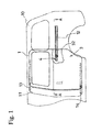
- a driving apparatus 4 is installed in the slide door 1 and a cable 31 comprises wires 31a and 31b that is wound on and/or out the driving apparatus 4.
- a pair of pulleys 32 (32a and 32b) is installed so that the slide door 1 slides along the center guide rail 12.
- Each of the wires 31a and 31b is fixed to an output dram 8 (Fig. 3) of the driving apparatus 4 at one end and wound on the dram while each of the wires 31a and 31b is fixed near of front end of the center guide rail to the side body 10 at the other end.
- the wires 31a and 31b are guided by the pulleys 31a and 32b so as to be passed through the center guide rail 12.
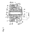
- the driving apparatus 4 comprises a housing 5, a reduction mechanism 6, a clutch 7 and an output dram 8.
- the housing 5 comprises a cover 5a and a base 5b and the cover 5a is fixed to the base by a connecting member (not shown).
- the reduction mechanism 6, the clutch 7 and the output dram 8 are accommodated in a space of the housing 5.
- Bearings 5c and 5d are fixed to the cover 5a and the base 5b, respectively, so that a rotational shaft S is supported on the housing 5 therethrough.
- the well-known reduction mechanism 6 comprises a worm gear 6a fixed to an output shaft of a motor and a disk-shaped worm wheel gear (input member) 6b that is geared with the worm gear 6a.
- the worm wheel gear 6b is rotatably supported on the shaft S through a cylindrical spacer sp.
- the spacer sp is fixed to the gear 6b so that the gear 6b and the spacer sp uniformly rotate.
- the clutch 7 comprises a solenoid mechanism 7a and an armature 7b.
- the solenoid mechanism 7a comprises a cylindrical-shaped core 7c for holding a coil C wound on a bobbin as well as a disk-shaped rotor 7d facing to the armature 7b and the core 7c in axial direction.
- the core 7c made of a magnetic material is fixed to the cover 5a of the housing 5.
- the rotor 7d made of a magnetic material is fixed to the shaft S so as to integrally rotate.
- the output dram 8 is fixed to an outer circumference 7e of the rotor 7d.
- the disk-shaped armature 7b made of magnetic material is located between the worm wheel gear 6b and the rotor 7d so that upper and lower planes of the armature 7b face an upper side of the worm wheel gear 6b and a lower plane of the rotor 7d, respectively.
- the armature 7b is rotatably and movably, in axial direction, supported on the spacer sp so that the armature 7b is rotatably and movably, in axial direction, supported on the shaft S through the spacer sp.
- a plurality of holes 7h are provided in the armature 7b so that a plurality of projections 6p of the worm wheel gear 6b is inserted into the holes 7h, respectively.
- the worm wheel gear 6b and the armature 7b are connected each other through the projections 6p and the holes 7h.
- the armature 7b integrally rotates with the worm wheel gear 6b so that a driving torque of the motor is transmitted to the armature 7b through the reduction mechanism 6.
- the output dram 8 made of resin is cylindrically shaped.
- the output dram 8 is fixed on an outer portion 7e of the rotor 7d so that the rotor 7d and the output dram 8 are integrally rotate.
- the armature 7b, the core 7c and the rotor 7d are located near by the output dram 8.
- most portion of the clutch 7 is accommodated in the inner space of the cylindrical-shaped output dram 8.
- a dead-volume space of the output dram 8 is occupied by the clutch 7 so that space is sufficiently used in axial direction of the shaft S.
- a ring-shaped magnet 9 is fixed on the upper face of the output dram 8 so that N- and S-poles of the magnet 9 are alternatively arranged. Revolution number and direction are detected by the magnet 9 in cooperation with a hole IC 9.
- the coil C of the solenoid mechanism 7a is energized so that the armature 7b and the rotor 7d are frictionally engaged each other.
- the driving torque of the motor is transmitted to the rotor 7d since the torque passes through the reduction mechanism 6 and the armature 7b. That is, the armature 7b and the rotor 7d integrally rotate each other so that the output dram 8 also rotates with the rotor 7d integrally.
- One of the wires 31a and 31b is wound on the output dram 8 and the other of them is wound out the output dram 8 so that the slide door 1 moves in open/close direction.
- the coil C of the solenoid mechanism 7a is not energized so that the armature 7b and the rotor 7d are not engaged each other.
- the slide door 1 is, therefore, manually operated and the output dram 8 rotates in accordance with the movement of the slide door 1 through the wires 31a and 31b.
- the rotation of the output dram 8 is not transmitted to the armature 7b and the clutch 6. Namely, smooth and/or easy manually operation of the slide door is achieved.
- a worm wheel gear 6b and a rotor 7d are fixed to a shaft S2 so that the gear 6b and the rotor 7d integrally rotate.
- a driving torque of a motor is transmitted to the rotor 7d through a reduction mechanism 6.
- An armature 7b is rotatably and movably, in axial direction, supported on the shaft S2 through the spacer sp2. The armature 7b is located between the rotor 7d and an output dram 8.
- a plurality of holes 7h is provided in the armature 7b so that a plurality of projections 8p of the output dram 8 is inserted into the holes 7h, respectively.
- the armature 7b and the output dram 8 are connected each other through the holes 7h and the projections 8p.
- the output dram 8 is formed cup-shaped in axial direction so that a clutch comprising the armature 7b, a core 7c and the rotor 7d is accommodated in the inner space of the output dram 8.
- a worm wheel gear 6b and a rotor 7d are fixed to a spacer sp3 so that the gear 6b and the rotor 7d are roratably supported on a shaft S3 through the spacer sp3.
- the gear 6b and the rotor 7d integrally rotate each other.
- a driving torque of a motor is transmitted to the rotor 7d through a reduction mechanism 6.
- An armature 7b is rotatably and movably, in axial direction, supported on the shaft S3 through the spacer sp4.
- the armature 7b is located between the rotor 7d and an output dram 8.
- a plurality of holes 7h is provided in the armature 7b so that a plurality of projections 8p of the output dram 8 is inserted into the holes 7h, respectively.
- the armature 7b and the output dram 8 are connected each other through the holes 7h and the projections 8p.
- the output dram 8 is formed cup-shaped in axial direction so that a clutch comprising the armature 7b, a core 7c and the rotor 7d is accommodated in the inner space of the output dram 8.
Landscapes
- Power-Operated Mechanisms For Wings (AREA)
- Mechanical Operated Clutches (AREA)
Applications Claiming Priority (2)
| Application Number | Priority Date | Filing Date | Title |
|---|---|---|---|
| JP2004046471A JP4479272B2 (ja) | 2004-02-23 | 2004-02-23 | 開閉体の駆動装置 |
| JP2004046471 | 2004-02-23 |
Publications (3)
| Publication Number | Publication Date |
|---|---|
| EP1566511A2 true EP1566511A2 (fr) | 2005-08-24 |
| EP1566511A3 EP1566511A3 (fr) | 2008-12-03 |
| EP1566511B1 EP1566511B1 (fr) | 2014-11-12 |
Family
ID=34709180
Family Applications (1)
| Application Number | Title | Priority Date | Filing Date |
|---|---|---|---|
| EP05003033.7A Expired - Lifetime EP1566511B1 (fr) | 2004-02-23 | 2005-02-14 | Dispositif d'entraînement pour un élément mobile de véhicule |
Country Status (3)
| Country | Link |
|---|---|
| US (1) | US7275629B2 (fr) |
| EP (1) | EP1566511B1 (fr) |
| JP (1) | JP4479272B2 (fr) |
Cited By (4)
| Publication number | Priority date | Publication date | Assignee | Title |
|---|---|---|---|---|
| EP1898514A1 (fr) * | 2006-09-05 | 2008-03-12 | Mitsui Mining and Smelting Co., Ltd | Appareil d'entraînement d'un élément fermant/ouvrant de véhicule |
| US8109041B2 (en) | 2006-08-22 | 2012-02-07 | Mitsui Kinzoku Act Corporation | Powered device for vehicle sliding member |
| EP2246210A4 (fr) * | 2008-02-28 | 2014-03-05 | Aisin Seiki | Dispositif d'ouverture/fermeture pour une portière de véhicule |
| CN108756581A (zh) * | 2018-06-17 | 2018-11-06 | 桂林京达科技有限公司 | 一种安全自锁/解锁装置及自动车辆外滑移门系统 |
Families Citing this family (18)
| Publication number | Priority date | Publication date | Assignee | Title |
|---|---|---|---|---|
| JP4789539B2 (ja) * | 2005-08-05 | 2011-10-12 | アイシン精機株式会社 | 駆動装置 |
| US8322074B2 (en) * | 2005-08-29 | 2012-12-04 | Mitsui Kinzoku Act Corporation | Power unit for power slide apparatus |
| JP2007176464A (ja) * | 2005-12-28 | 2007-07-12 | Mitsui Mining & Smelting Co Ltd | 移動体用の動力ユニット |
| JP4806319B2 (ja) | 2006-09-08 | 2011-11-02 | 三井金属アクト株式会社 | 開閉体の駆動装置 |
| JP4831416B2 (ja) * | 2006-11-07 | 2011-12-07 | アイシン精機株式会社 | 電磁クラッチ装置 |
| JP4950644B2 (ja) * | 2006-12-07 | 2012-06-13 | 三井金属アクト株式会社 | 開閉体の駆動装置 |
| JP2008151228A (ja) * | 2006-12-15 | 2008-07-03 | Minebea Co Ltd | 電磁クラッチ装置およびその製造方法 |
| JP4993357B2 (ja) * | 2007-05-07 | 2012-08-08 | 三井金属アクト株式会社 | 車両等における開閉体の駆動装置 |
| JP4971900B2 (ja) * | 2007-07-31 | 2012-07-11 | ミネベア株式会社 | 電磁クラッチ |
| US20110036678A1 (en) * | 2007-11-15 | 2011-02-17 | Aisin Seiki Kabushiki Kaisha | Electromagnetic clutch |
| JP2010014149A (ja) * | 2008-07-01 | 2010-01-21 | Denso Corp | 電磁クラッチ |
| JP5424498B2 (ja) * | 2011-01-31 | 2014-02-26 | 三井金属アクト株式会社 | 移動体用の動力ユニット |
| JP5545878B2 (ja) * | 2011-02-04 | 2014-07-09 | 三井金属アクト株式会社 | 動力スライド装置用動力ユニット |
| JP5718079B2 (ja) * | 2011-02-07 | 2015-05-13 | 三井金属アクト株式会社 | 開閉体の駆動装置 |
| JP5271370B2 (ja) * | 2011-02-08 | 2013-08-21 | 三井金属アクト株式会社 | 動力スライド装置の動力ユニット |
| JP5297474B2 (ja) * | 2011-02-09 | 2013-09-25 | 三井金属アクト株式会社 | 開閉体の駆動装置 |
| JP5297478B2 (ja) * | 2011-02-10 | 2013-09-25 | 三井金属アクト株式会社 | 開閉体の駆動装置 |
| JP5430013B2 (ja) * | 2011-02-21 | 2014-02-26 | 三井金属アクト株式会社 | 動力スライド装置用動力ユニット |
Family Cites Families (11)
| Publication number | Priority date | Publication date | Assignee | Title |
|---|---|---|---|---|
| US4566574A (en) * | 1981-10-07 | 1986-01-28 | Pt Components, Inc. | Multiple-disc electromagnetic clutch |
| JPH0211236U (fr) * | 1988-07-04 | 1990-01-24 | ||
| US5138795A (en) * | 1990-04-25 | 1992-08-18 | General Motors Corporation | Power sliding door closer |
| US5909075A (en) * | 1998-04-08 | 1999-06-01 | Heimark; Charles L. | Belt transmission and clutch for vehicle accessories |
| BR9915954B1 (pt) * | 1998-12-03 | 2012-01-10 | atuador energizado, e, tranca energizada | |
| JP3452548B2 (ja) * | 2000-12-28 | 2003-09-29 | 三井金属鉱業株式会社 | 車両スライド扉用動力スライド装置の制御方法 |
| JP3867534B2 (ja) * | 2001-03-02 | 2007-01-10 | アイシン精機株式会社 | 車両用ドア開閉駆動装置 |
| EP1401752B1 (fr) * | 2001-06-19 | 2011-08-17 | Delphi Technologies, Inc. | Ensemble entrainement par cable |
| JP3530839B2 (ja) * | 2001-09-21 | 2004-05-24 | 三井金属鉱業株式会社 | 車両スライド扉用動力スライド装置 |
| JP4254212B2 (ja) * | 2002-11-27 | 2009-04-15 | アイシン精機株式会社 | 車両用開閉体の開閉制御システム |
| US7243461B2 (en) * | 2003-03-19 | 2007-07-17 | Rogers Jr Lloyd W | Hinge mechanism for a sliding door |
-
2004
- 2004-02-23 JP JP2004046471A patent/JP4479272B2/ja not_active Expired - Fee Related
-
2005
- 2005-02-14 EP EP05003033.7A patent/EP1566511B1/fr not_active Expired - Lifetime
- 2005-02-22 US US11/061,530 patent/US7275629B2/en not_active Expired - Lifetime
Cited By (6)
| Publication number | Priority date | Publication date | Assignee | Title |
|---|---|---|---|---|
| US8109041B2 (en) | 2006-08-22 | 2012-02-07 | Mitsui Kinzoku Act Corporation | Powered device for vehicle sliding member |
| EP1898514A1 (fr) * | 2006-09-05 | 2008-03-12 | Mitsui Mining and Smelting Co., Ltd | Appareil d'entraînement d'un élément fermant/ouvrant de véhicule |
| US8910767B2 (en) | 2006-09-05 | 2014-12-16 | Mitsui Kinzoku Act Corporation | Open/close member driving apparatus |
| EP2246210A4 (fr) * | 2008-02-28 | 2014-03-05 | Aisin Seiki | Dispositif d'ouverture/fermeture pour une portière de véhicule |
| CN108756581A (zh) * | 2018-06-17 | 2018-11-06 | 桂林京达科技有限公司 | 一种安全自锁/解锁装置及自动车辆外滑移门系统 |
| CN108756581B (zh) * | 2018-06-17 | 2023-10-13 | 桂林京达科技有限公司 | 一种安全自锁/解锁装置及自动车辆外滑移门系统 |
Also Published As
| Publication number | Publication date |
|---|---|
| JP4479272B2 (ja) | 2010-06-09 |
| EP1566511A3 (fr) | 2008-12-03 |
| JP2005232918A (ja) | 2005-09-02 |
| EP1566511B1 (fr) | 2014-11-12 |
| US7275629B2 (en) | 2007-10-02 |
| US20050183924A1 (en) | 2005-08-25 |
Similar Documents
| Publication | Publication Date | Title |
|---|---|---|
| EP1566511B1 (fr) | Dispositif d'entraînement pour un élément mobile de véhicule | |
| JP5184012B2 (ja) | 車両用自動開閉装置 | |
| US8484893B2 (en) | Clutch, motor and vehicle door opening/closing device | |
| JP3913658B2 (ja) | 電磁クラッチ付モータ | |
| JP5602405B2 (ja) | スライドドア自動開閉装置 | |
| JP4939877B2 (ja) | 開閉体の駆動装置 | |
| JP4815275B2 (ja) | クラッチおよびこれを用いた減速機付きモータ並びに車両用自動開閉装置 | |
| JP5484951B2 (ja) | クラッチ、モータ及び車両用ドア開閉装置 | |
| KR102783474B1 (ko) | 차량의 슬라이딩도어용 자동개폐장치 | |
| JP3627744B2 (ja) | 開閉体の駆動装置 | |
| JP2009296698A (ja) | 減速機構付き電動モータ | |
| JP5490565B2 (ja) | クラッチ、モータ及び車両用ドア開閉装置 | |
| JP2009293643A (ja) | 減速機構付き電動モータ | |
| JP4851885B2 (ja) | 開閉体の駆動装置 | |
| JP4702195B2 (ja) | 車両用駆動装置 | |
| JP5115760B2 (ja) | 開閉体駆動装置 | |
| CN110375102B (zh) | 排水阀控制装置 | |
| JP4998604B2 (ja) | 開閉体駆動装置 | |
| JP4896635B2 (ja) | クラッチ、モータ及び車両用ドア開閉装置 | |
| JP5297478B2 (ja) | 開閉体の駆動装置 | |
| JP4950644B2 (ja) | 開閉体の駆動装置 | |
| JP2006125452A (ja) | 電磁クラッチ装置 | |
| JP5718079B2 (ja) | 開閉体の駆動装置 | |
| JP5297474B2 (ja) | 開閉体の駆動装置 | |
| JP2007303513A (ja) | 電磁クラッチおよびこれを用いた車両用自動開閉装置 |
Legal Events
| Date | Code | Title | Description |
|---|---|---|---|
| PUAI | Public reference made under article 153(3) epc to a published international application that has entered the european phase |
Free format text: ORIGINAL CODE: 0009012 |
|
| AK | Designated contracting states |
Kind code of ref document: A2 Designated state(s): AT BE BG CH CY CZ DE DK EE ES FI FR GB GR HU IE IS IT LI LT LU MC NL PL PT RO SE SI SK TR |
|
| AX | Request for extension of the european patent |
Extension state: AL BA HR LV MK YU |
|
| PUAL | Search report despatched |
Free format text: ORIGINAL CODE: 0009013 |
|
| AK | Designated contracting states |
Kind code of ref document: A3 Designated state(s): AT BE BG CH CY CZ DE DK EE ES FI FR GB GR HU IE IS IT LI LT LU MC NL PL PT RO SE SI SK TR |
|
| AX | Request for extension of the european patent |
Extension state: AL BA HR LV MK YU |
|
| 17P | Request for examination filed |
Effective date: 20090602 |
|
| AKX | Designation fees paid |
Designated state(s): DE FR GB |
|
| 17Q | First examination report despatched |
Effective date: 20090828 |
|
| GRAP | Despatch of communication of intention to grant a patent |
Free format text: ORIGINAL CODE: EPIDOSNIGR1 |
|
| INTG | Intention to grant announced |
Effective date: 20140703 |
|
| GRAP | Despatch of communication of intention to grant a patent |
Free format text: ORIGINAL CODE: EPIDOSNIGR1 |
|
| GRAS | Grant fee paid |
Free format text: ORIGINAL CODE: EPIDOSNIGR3 |
|
| INTG | Intention to grant announced |
Effective date: 20140901 |
|
| GRAA | (expected) grant |
Free format text: ORIGINAL CODE: 0009210 |
|
| AK | Designated contracting states |
Kind code of ref document: B1 Designated state(s): DE FR GB |
|
| REG | Reference to a national code |
Ref country code: GB Ref legal event code: FG4D |
|
| REG | Reference to a national code |
Ref country code: DE Ref legal event code: R096 Ref document number: 602005045126 Country of ref document: DE Effective date: 20141224 |
|
| REG | Reference to a national code |
Ref country code: DE Ref legal event code: R097 Ref document number: 602005045126 Country of ref document: DE |
|
| PLBE | No opposition filed within time limit |
Free format text: ORIGINAL CODE: 0009261 |
|
| STAA | Information on the status of an ep patent application or granted ep patent |
Free format text: STATUS: NO OPPOSITION FILED WITHIN TIME LIMIT |
|
| 26N | No opposition filed |
Effective date: 20150813 |
|
| GBPC | Gb: european patent ceased through non-payment of renewal fee |
Effective date: 20150214 |
|
| REG | Reference to a national code |
Ref country code: FR Ref legal event code: PLFP Year of fee payment: 12 |
|
| PG25 | Lapsed in a contracting state [announced via postgrant information from national office to epo] |
Ref country code: GB Free format text: LAPSE BECAUSE OF NON-PAYMENT OF DUE FEES Effective date: 20150214 |
|
| REG | Reference to a national code |
Ref country code: FR Ref legal event code: PLFP Year of fee payment: 13 |
|
| REG | Reference to a national code |
Ref country code: FR Ref legal event code: PLFP Year of fee payment: 14 |
|
| PGFP | Annual fee paid to national office [announced via postgrant information from national office to epo] |
Ref country code: DE Payment date: 20231228 Year of fee payment: 20 |
|
| PGFP | Annual fee paid to national office [announced via postgrant information from national office to epo] |
Ref country code: FR Payment date: 20240103 Year of fee payment: 20 |
|
| REG | Reference to a national code |
Ref country code: DE Ref legal event code: R071 Ref document number: 602005045126 Country of ref document: DE |