EP1566559A1 - Verfahren zur Herstellung von gesinterten mechanischen Teilen - Google Patents
Verfahren zur Herstellung von gesinterten mechanischen Teilen Download PDFInfo
- Publication number
- EP1566559A1 EP1566559A1 EP05101170A EP05101170A EP1566559A1 EP 1566559 A1 EP1566559 A1 EP 1566559A1 EP 05101170 A EP05101170 A EP 05101170A EP 05101170 A EP05101170 A EP 05101170A EP 1566559 A1 EP1566559 A1 EP 1566559A1
- Authority
- EP
- European Patent Office
- Prior art keywords
- punch
- compression
- cold deformation
- mechanical
- cold
- Prior art date
- Legal status (The legal status is an assumption and is not a legal conclusion. Google has not performed a legal analysis and makes no representation as to the accuracy of the status listed.)
- Withdrawn
Links
Images
Classifications
-
- B—PERFORMING OPERATIONS; TRANSPORTING
- B22—CASTING; POWDER METALLURGY
- B22F—WORKING METALLIC POWDER; MANUFACTURE OF ARTICLES FROM METALLIC POWDER; MAKING METALLIC POWDER; APPARATUS OR DEVICES SPECIALLY ADAPTED FOR METALLIC POWDER
- B22F5/00—Manufacture of workpieces or articles from metallic powder characterised by the special shape of the product
- B22F5/08—Manufacture of workpieces or articles from metallic powder characterised by the special shape of the product of toothed articles, e.g. gear wheels; of cam discs
-
- F—MECHANICAL ENGINEERING; LIGHTING; HEATING; WEAPONS; BLASTING
- F16—ENGINEERING ELEMENTS AND UNITS; GENERAL MEASURES FOR PRODUCING AND MAINTAINING EFFECTIVE FUNCTIONING OF MACHINES OR INSTALLATIONS; THERMAL INSULATION IN GENERAL
- F16D—COUPLINGS FOR TRANSMITTING ROTATION; CLUTCHES; BRAKES
- F16D23/00—Details of mechanically-actuated clutches not specific for one distinct type
- F16D23/02—Arrangements for synchronisation, also for power-operated clutches
- F16D23/04—Arrangements for synchronisation, also for power-operated clutches with an additional friction clutch
-
- F—MECHANICAL ENGINEERING; LIGHTING; HEATING; WEAPONS; BLASTING
- F16—ENGINEERING ELEMENTS AND UNITS; GENERAL MEASURES FOR PRODUCING AND MAINTAINING EFFECTIVE FUNCTIONING OF MACHINES OR INSTALLATIONS; THERMAL INSULATION IN GENERAL
- F16D—COUPLINGS FOR TRANSMITTING ROTATION; CLUTCHES; BRAKES
- F16D23/00—Details of mechanically-actuated clutches not specific for one distinct type
- F16D23/02—Arrangements for synchronisation, also for power-operated clutches
- F16D23/04—Arrangements for synchronisation, also for power-operated clutches with an additional friction clutch
- F16D23/06—Arrangements for synchronisation, also for power-operated clutches with an additional friction clutch and a blocking mechanism preventing the engagement of the main clutch prior to synchronisation
-
- F—MECHANICAL ENGINEERING; LIGHTING; HEATING; WEAPONS; BLASTING
- F16—ENGINEERING ELEMENTS AND UNITS; GENERAL MEASURES FOR PRODUCING AND MAINTAINING EFFECTIVE FUNCTIONING OF MACHINES OR INSTALLATIONS; THERMAL INSULATION IN GENERAL
- F16D—COUPLINGS FOR TRANSMITTING ROTATION; CLUTCHES; BRAKES
- F16D2250/00—Manufacturing; Assembly
Definitions
- the present invention relates to a method of manufacture of sintered mechanical parts, including parts sintered mechanical having a complex shape.
- the current invention finds particular application for the manufacture mechanical parts used in a gearbox, such as a player, a synchronizing ring, a hub, etc.
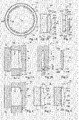
- FIG 1A is a schematic front view of a walkman 10 classic gearbox.
- the player 10 comprises an annular body 11 traversed by an opening cylindrical 12 of axis D defining an inner side wall 13 of the annular body 11 on which are distributed teeth 14 separated by splines 15.
- the annular body 11 comprises an outer side wall 16 on which is defined a groove (not shown).
- the player 10 is mounted coaxially on a solidarity hub a drive shaft D axis of the gearbox.
- the hub drives the player 10 in rotation about the axis D by cooperation of the teeth 14 of the player 11 with teeth of the hub.
- a fork cooperating with the throat of the side wall 16 of the annular body 11 can slide the player 10 relative to the hub along the axis D.
- At least one pinion is rotatably mounted on the drive shaft to side of the player 10.
- the 10 When selecting a report of speeds using the free gear adjacent to the player 10, the 10 is moved axially relative to the hub for have the teeth 14 of the player 10 cooperate with a crown pinion of the loose pinion so as to make the pinion integral with the walkman and drive the pinion in rotation.
- Figure 1B is a schematic section of the player 10 of Figure 1A along the line 1B-1B and Figure 1C is a view schematic of the player 10 of Figure 1B according to the direction F.
- the tooth 14 comprises a central body 17 substantially elongated parallelepiped extending along the axis D and having two opposite side faces 18, 19 each having a common edge with the annular body 11 and an upper face 20, opposite to the annular body 11, connecting the lateral faces 18, 19.
- the central body 17 comprises, along the axis D, two end portions 21A, 21B opposite.
- Each serving end 21A, 21B is defined by three inclined faces 22A, 23A, 24A and 22B, 23B, 24B.
- the inclined faces 22A, 24A, 22B, 24B extend the lateral faces 18, 19 of the central body 17 to meet and the inclined faces 23A, 23B extend the upper face 20 of the central body 17.
- the inclined faces 22A 24A and 22B to 24B in particular make it possible to optimize the cooperation of the teeth 14 with the claws of the crown to pinion of the free gear when a report of speeds.
- the upper face 20 further comprises, in the central part, a projecting portion 25 delimited, along the axis D, by two faces inclined 26A, 26B.
- the protruding portion 25 is generally missing from the teeth 14 of the player 10 which do not cooperate with the arming system.
- the player 10 is generally made from a one-piece piece made of steel obtained by forging and machining. he It would be advantageous to make the sintered steel walkman.
- the sintering process which corresponds to the heating of a blank piece obtained by cold pressing a mixture of powders usually makes it possible to obtain a coin directly from desired dimensions, which reduces the number of steps machining to predict and therefore reduces the cost of manufacturing the room.
- Figure 2A is a partial and schematic sectional view an example of a tool 30 that can be used for manufacturing of the player 10 previously described by sintering during the step cold compression.
- the tool 30 corresponds to a tool classic for the manufacture of sintered parts. Only one part of the tool 30 is shown, the tool 30 having a symmetry of revolution around the D axis (not shown and which would be vertical and located to the right of Figure 2A).
- the realization of the blank part consists in filling the cavity 37 of a mixture of powders and to compress the mixture of powders by a displacement of the punch-pin 34 in a compression direction indicated by an arrow in Figure 2A.
- the punch-pin 34 is moved in a direction opposite to the direction compression.
- the outer side wall 16 of the player 10 is defined by the matrix 32 while the teeth 14 are defined by the spindle punch 34 and the lower punch 36. More specifically, the spindle punch 34 comprises impressions 38, each impression 38 having a shape complementary to a portion of a tooth 14. Given the direction of movement of the punch-pin 34, it is only possible to define by means of each impression 38 of the spindle punch 34, the walls side walls 18, 19, the inclined faces 22A, 23A, 24A of the end portion 21A, and the inclined face 26A of the face upper 20, to allow the release of the punch-pin 34.
- the inclined faces 22B, 23B, 24B of the end portion 21B and the inclined face 26B of the upper face 20 are surfaces that can not be obtained by means of footprint 38.
- Figure 2B shows a partial section of the Figure 2A according to line 2B-2B.
- the lower punch 36 comprises, for each imprint 38, a protuberance 39 corresponding, on which can slide the footprint 38 of punch-pin 34.
- Each protuberance 39 includes a fingerprint 40 which defines the inclined faces 22B and 24B of the tooth 14 when cold compression. It is not possible to provide protrusion 39 which extends sufficiently in the footprint 38 corresponding to form the inclined faces 23B and 26B.
- the inclined faces 23B and 26B are therefore generally obtained by subsequent machining steps of the sintered part. Such Machining steps increase the cost of manufacturing the part. It can also be difficult to obtain by machining classic complex surfaces.
- Figure 3 schematically represents a section of a tooth 14 obtained by the tool 30.
- the end portions of the protuberance 39 can not correspond to sharp angles but necessarily include flats 41. This leads to the formation of flats. corresponding at the junction between the faces 22B, 24B and the side walls 18, 19 on the tooth 14 obtained.
- the lateral faces 18, 19 being defined by the impression 38 of the punch-pin 34 and the inclined faces 22B, 24B being defined by the imprint 40 of the lower punch 36, it is not possible to precisely control the shape of the joining surface between the inclined faces 22B, 24B and the side walls 18, 19 on the tooth 14 obtained. We obtain usually burrs or unwanted surface defects at the junction surfaces.
- a step deburring for example by brushing, to improve the surface geometry at the junction surfaces between the inclined faces 22B, 24B and the side walls 18, 19. It however, it is difficult to precisely control the radius of curvature of the joining surfaces by the deburring method.
- the deburring process can undesirably the shape of the junction surface between the inclined faces 22B and 24B which is correctly defined, for each tooth 14, by the associated footprint 40 of the lower punch 36.
- Document FR 2 730 775 describes a method of manufacturing a sliding sleeve comprising a step of sintering of a blank from a sintering powder and a step of modifying the sintered part, by stamping, to form undercut surfaces, the step of modification resulting only in plastic deformations small amplitudes of the sintered part.
- the present invention aims to obtain a method of manufacture by sintering of a mechanical part allowing reduce the number of machining steps required for training of surfaces of the mechanical part.
- the present invention also aims at obtaining a manufacturing process by sintering a mechanical part to eliminate the appearance of flats, burrs or other surface defects in the mechanical part formed by compression of a mixture of powders.
- the present invention provides a method of manufacturing a steel mechanical part sintered, comprising the steps of: compressing a powder mixture; sintering; and cold deformation of the sintered part, the plastic deformation obtained according to perpendicular to the surface of the sintered part, being, at less at a part of the sintered part, greater than 10%.
- the step of cold deformation is achieved by means of a monobloc punch comprising a fingerprint having a shape complementary to a surface to be formed on the mechanical part.
- the step of compression is achieved by means of a monobloc punch comprising a fingerprint having a shape complementary to a surface to be formed on the mechanical part.
- first surfaces located at a first region of the room mechanics, are formed during the compression step and second surfaces, located at a second region of the separate mechanical part of the first region, are formed during the cold deformation step.
- the first surfaces and the second surfaces are symmetrical with respect to a plane of symmetry of the mechanical part and the stage of compression is achieved by means of a punch comprising imprints having a shape complementary to the first surfaces, the cold deformation step being carried out by means of of the same punch, the second surfaces being formed by means of stamp imprints.
- the piece Mechanical is a walkman gearbox.
- the cold deformation step entails, in some locations of the blank part, plastic deformation, along the perpendicular to the surface of the blank part, less than 10% locally, and able to reach and exceed 20% to 30%.
- the applicant has shown that, for mixtures of powders corresponding to certain sintered steels, even with such deformations, the sintered part is not weakened and retains the mechanical strength properties sought.
- stages of cold compression and deformation to cold make it possible to obtain a sintered part practically directly to the desired dimensions. It is not then necessary to provide for subsequent machining steps for correct the surfaces obtained during the compression steps to cold and cold deformation.
- formed surfaces the cold compression or cold deformation steps are obtained by fingerprints provided in a single piece of compression tool or forming tool, and not by the cooperation of several pieces of the compression tool or the forming tool moving relative to each other. Such surfaces therefore have no defects such as flats or burrs that require correction steps additional.
- the present method can be followed by a step classic calibration, in which the piece is introduced after the cold deformation step in a caliber for correct minor defects, and / or to increase overall the density of the room.
- a calibration step entails only minor deformations corresponding to a plastic deformation of the material generally less than 6%.
- the calibration and cold deformation steps can be performed simultaneously.
- FIG. 4 represents an exemplary embodiment of a tool 50 used for the cold pressing step of the method according to the invention for the manufacture of a player.
- the tool 50 is in fact similar to the tool 30 shown in FIG. 2A and the common elements are indicated by the same references.
- the main difference is that in the present invention the lower punch 36 does not include fingerprints 40 at the level protuberances 39 by means of which were formed, for each tooth 14, the inclined faces 22B, 24B of the portion end 21B during the cold compression step as this has been described in connection with Figure 2A.
- Figure 5 is a partial and schematic section of the blank part 55 obtained after the compression step in cold.
- An intermediate tooth 56 of the blank part 55 is represented. Only the inclined faces 22A, 23A, 24A (the face inclined 24A not being visible in Figure 5) of the portion end 21A and the inclined face 26A of the projecting portion 25 are made on the intermediate tooth 56 during the step cold compression.
- the inclined faces 22A, 24A being obtained by means of the impression 38 of the spindle punch 34, the joining surfaces between the side walls 18, 19 of the intermediate tooth 56 and the inclined faces 22A, 24A are free from flats, burrs or other surface defects.
- the intermediate tooth 56 may comprise, at the level of the end portion 21B, a simple flat face 57 perpendicular to the axis D.
- a simple flat face 57 perpendicular to the axis D.
- each tooth 14 the end portions 21A, 21B and the faces inclined 26A, 26B are symmetrical.
- the piece sketch 55 is then returned and can be re-entered in the tool 50 or in a tool similar to the tool 50, the end portions 21A of intermediate teeth 56 coming into contact with the lower punch 36.
- the displacement of the punch-pin 34 causes cold deformation of the blank part 55.
- Each intermediate tooth 56 is deformed cold for forming the inclined faces 22B, 23B, 24B of the portion 21B end and the inclined face 26B of the projecting portion 25.
- the removal of the spindle punch 34 from the tool 50 with respect to the piece thus deformed is made without difficulty.
- the tool of forming used for the cold deformation step is necessarily different from the compression tool used for the cold compression step.
- Figure 6 is a schematic section of the player 10 obtained after the cold deformation step for which the tooth surfaces 14 formed in the cold deformation step are shown in thick lines.
- the faces inclined 22B, 23B, 24B of the end portion 21B being obtained by means of the impression 38 of the spindle punch 34, the joining surfaces between the side walls 18, 19 and the inclined faces 22B, 24B are free from burrs or other surface defects. It is not necessary to provide for subsequent deburring step.
- the pressures used in the compression step at cold and at the cold deformation stage, the temperature used in the sintering stage and the powder mixture used depend in particular on the part to be made.
- the mixture of powders used corresponds to a classic powder mix for obtaining sintered steels and the cold pressing step can be performed at pressures greater than 1000 Megapascals.
- the sintering step is then, for example, made in an oven at temperatures that can reach example 1150 ° C and the cold deformation step is, for example example, carried out under pressures of the order of 600 to 800 Megapascals.
- the present invention is capable of various variations and modifications that will appear to man art.
- the present invention has been described for the manufacture of a walkman, she finds a application for the manufacture of other mechanical parts, like, for example, a hub, a timing ring, a starter pinion, clutch gear, helical gear or any other part with complex surfaces that can not be be performed in a single compression operation.
Landscapes
- Engineering & Computer Science (AREA)
- General Engineering & Computer Science (AREA)
- Mechanical Engineering (AREA)
- Manufacturing & Machinery (AREA)
- Powder Metallurgy (AREA)
Applications Claiming Priority (2)
| Application Number | Priority Date | Filing Date | Title |
|---|---|---|---|
| FR0450282 | 2004-02-17 | ||
| FR0450282A FR2866254B1 (fr) | 2004-02-17 | 2004-02-17 | Procede de fabrication de pieces mecaniques frittees |
Publications (1)
| Publication Number | Publication Date |
|---|---|
| EP1566559A1 true EP1566559A1 (de) | 2005-08-24 |
Family
ID=34708045
Family Applications (1)
| Application Number | Title | Priority Date | Filing Date |
|---|---|---|---|
| EP05101170A Withdrawn EP1566559A1 (de) | 2004-02-17 | 2005-02-16 | Verfahren zur Herstellung von gesinterten mechanischen Teilen |
Country Status (2)
| Country | Link |
|---|---|
| EP (1) | EP1566559A1 (de) |
| FR (1) | FR2866254B1 (de) |
Cited By (1)
| Publication number | Priority date | Publication date | Assignee | Title |
|---|---|---|---|---|
| ES2322923A1 (es) * | 2005-12-23 | 2009-07-01 | Pmg Asturias Powder Metal, S.A. | Cubo de sincronismo modificado y procedimiento para la fabricacion del mismo. |
Citations (2)
| Publication number | Priority date | Publication date | Assignee | Title |
|---|---|---|---|---|
| FR2730775A1 (fr) * | 1995-02-16 | 1996-08-23 | Miba Sintermetall Ag | Procede de fabrication d'un manchon coulissant pour le dispositif de synchronisation d'une boite de vitesses a engrenage |
| WO2000025960A1 (de) * | 1998-11-02 | 2000-05-11 | Gkn Sinter Metals Gmbh | Verfahren zur herstellung eines gesinterten bauteils mit nachverformung des grünlings |
-
2004
- 2004-02-17 FR FR0450282A patent/FR2866254B1/fr not_active Expired - Fee Related
-
2005
- 2005-02-16 EP EP05101170A patent/EP1566559A1/de not_active Withdrawn
Patent Citations (2)
| Publication number | Priority date | Publication date | Assignee | Title |
|---|---|---|---|---|
| FR2730775A1 (fr) * | 1995-02-16 | 1996-08-23 | Miba Sintermetall Ag | Procede de fabrication d'un manchon coulissant pour le dispositif de synchronisation d'une boite de vitesses a engrenage |
| WO2000025960A1 (de) * | 1998-11-02 | 2000-05-11 | Gkn Sinter Metals Gmbh | Verfahren zur herstellung eines gesinterten bauteils mit nachverformung des grünlings |
Cited By (2)
| Publication number | Priority date | Publication date | Assignee | Title |
|---|---|---|---|---|
| ES2322923A1 (es) * | 2005-12-23 | 2009-07-01 | Pmg Asturias Powder Metal, S.A. | Cubo de sincronismo modificado y procedimiento para la fabricacion del mismo. |
| ES2322923B1 (es) * | 2005-12-23 | 2010-04-23 | Pmg Asturias Powder Metal, S.A. | Cubo de sincronismo modificado y procedimiento para la fabricacion del mismo. |
Also Published As
| Publication number | Publication date |
|---|---|
| FR2866254A1 (fr) | 2005-08-19 |
| FR2866254B1 (fr) | 2006-06-09 |
Similar Documents
| Publication | Publication Date | Title |
|---|---|---|
| FR2730775A1 (fr) | Procede de fabrication d'un manchon coulissant pour le dispositif de synchronisation d'une boite de vitesses a engrenage | |
| EP2512706B1 (de) | Verfahren zur herstellung einer gesinterten synchron-ring mit klauen | |
| JPS6245012B2 (de) | ||
| JP4350300B2 (ja) | シフトギアホイールの製造方法、その方法を実施する装置並びにその方法で製造されたシフトギアホイール | |
| FR2548933A1 (fr) | Corps en metal fritte muni d'au moins une denture | |
| FR2573700A1 (fr) | Corps de moyeu pour roue motrice de bicyclette ou similaire,et son procede de fabrication | |
| FR2866254A1 (fr) | Procede de fabrication de pieces mecaniques frittees | |
| FR2480633A1 (fr) | Matrice segmentee, notamment pour le matricage des metaux, procede de fabrication d'une telle matrice et procede de fabrication d'un chapeau de tete de bielle comportant utilisation d'une telle matrice | |
| EP1056957B1 (de) | Synchroring für synchronisiereinrichtung eines getriebes, und verfahren zur herstllung solch eines ringes aus einem stück blech | |
| JP4979086B2 (ja) | ギアポンプ用ロータの製造方法 | |
| FR2560540A1 (fr) | Procede pour la fabrication de dentures d'embrayage presentant des pentes de toit | |
| CA2945500A1 (fr) | Outillage de forgeage pour la fabrication d'une couronne laminee de forme, notamment pour la fabrication d'un disque de turbomachine | |
| FR2523010A1 (fr) | Procede de moletage coupant ou deformant, et des moyens de mise en oeuvre, destines a moleter ou rainurer des alesages ou portees cylindriques de pieces | |
| FR2777213A1 (fr) | Procede de fabrication de piece tubulaire metallique et d'arbre tubulaire composite | |
| FR2874411A1 (fr) | Boite de vitesses, en particulier pour un vehicule automobile, ainsi qu'un arbre ou des arbres pour une telle boite de vitesses et procede de fabrication de tels arbres | |
| FR2763267A1 (fr) | Procede de fabrication d'engrenages sur un arbre creux de boite de vitesses | |
| EP0250312B1 (de) | Verfahren zur Herstellung von Zahnrädern, deren Zahneingriffsflächen einen scharfkantigen Winkel bilden | |
| JP3681901B2 (ja) | 変速用クラッチのシンクロナイザコーンの製造方法 | |
| FR3133773A1 (fr) | Procédé et installation de fabrication par forgeage à chaud d’une pièce intermédiaire allongée | |
| EP1439925A1 (de) | Kaltformwerkzeug, -maschine und -verfahren | |
| FR2748677A1 (fr) | Procede de forgeage a froid pour fabriquer des moyeux d'embrayages de vehicules automobiles | |
| JP5276626B2 (ja) | マルチコーンシンクロの同期用クラッチ歯車 | |
| FR2813029A1 (fr) | Procede de fabrication d'un pignon de transmission, pignon de transmission obtenu et synchroniseur pour une transmission de vehicule automobile equipe d'un tel pignon | |
| EP1652600B1 (de) | Verfahren zum Warmwalzen und Umformen eines Werkstückes mit varierendem Querschnitt | |
| JPS5924547A (ja) | 筒状部品の外径形状加工方法 |
Legal Events
| Date | Code | Title | Description |
|---|---|---|---|
| PUAI | Public reference made under article 153(3) epc to a published international application that has entered the european phase |
Free format text: ORIGINAL CODE: 0009012 |
|
| AK | Designated contracting states |
Kind code of ref document: A1 Designated state(s): AT BE BG CH CY CZ DE DK EE ES FI FR GB GR HU IE IS IT LI LT LU MC NL PL PT RO SE SI SK TR |
|
| AX | Request for extension of the european patent |
Extension state: AL BA HR LV MK YU |
|
| 17P | Request for examination filed |
Effective date: 20060223 |
|
| AKX | Designation fees paid |
Designated state(s): AT BE BG CH CY CZ DE DK EE ES FI FR GB GR HU IE IS IT LI LT LU MC NL PL PT RO SE SI SK TR |
|
| 17Q | First examination report despatched |
Effective date: 20060919 |
|
| 17Q | First examination report despatched |
Effective date: 20060919 |
|
| STAA | Information on the status of an ep patent application or granted ep patent |
Free format text: STATUS: THE APPLICATION HAS BEEN WITHDRAWN |
|
| 18W | Application withdrawn |
Effective date: 20081212 |