EP1566627A1 - Feldverstärkter Oberfächenplasmonenresonanzbeugungssensor - Google Patents
Feldverstärkter Oberfächenplasmonenresonanzbeugungssensor Download PDFInfo
- Publication number
- EP1566627A1 EP1566627A1 EP05003435A EP05003435A EP1566627A1 EP 1566627 A1 EP1566627 A1 EP 1566627A1 EP 05003435 A EP05003435 A EP 05003435A EP 05003435 A EP05003435 A EP 05003435A EP 1566627 A1 EP1566627 A1 EP 1566627A1
- Authority
- EP
- European Patent Office
- Prior art keywords
- metal substrate
- diffraction
- receptor
- sensor according
- areas
- Prior art date
- Legal status (The legal status is an assumption and is not a legal conclusion. Google has not performed a legal analysis and makes no representation as to the accuracy of the status listed.)
- Withdrawn
Links
Images




Classifications
-
- B—PERFORMING OPERATIONS; TRANSPORTING
- B82—NANOTECHNOLOGY
- B82Y—SPECIFIC USES OR APPLICATIONS OF NANOSTRUCTURES; MEASUREMENT OR ANALYSIS OF NANOSTRUCTURES; MANUFACTURE OR TREATMENT OF NANOSTRUCTURES
- B82Y30/00—Nanotechnology for materials or surface science, e.g. nanocomposites
-
- B—PERFORMING OPERATIONS; TRANSPORTING
- B82—NANOTECHNOLOGY
- B82Y—SPECIFIC USES OR APPLICATIONS OF NANOSTRUCTURES; MEASUREMENT OR ANALYSIS OF NANOSTRUCTURES; MANUFACTURE OR TREATMENT OF NANOSTRUCTURES
- B82Y15/00—Nanotechnology for interacting, sensing or actuating, e.g. quantum dots as markers in protein assays or molecular motors
-
- G—PHYSICS
- G01—MEASURING; TESTING
- G01N—INVESTIGATING OR ANALYSING MATERIALS BY DETERMINING THEIR CHEMICAL OR PHYSICAL PROPERTIES
- G01N21/00—Investigating or analysing materials by the use of optical means, i.e. using sub-millimetre waves, infrared, visible or ultraviolet light
- G01N21/17—Systems in which incident light is modified in accordance with the properties of the material investigated
- G01N21/47—Scattering, i.e. diffuse reflection
- G01N21/4788—Diffraction
-
- G—PHYSICS
- G01—MEASURING; TESTING
- G01N—INVESTIGATING OR ANALYSING MATERIALS BY DETERMINING THEIR CHEMICAL OR PHYSICAL PROPERTIES
- G01N21/00—Investigating or analysing materials by the use of optical means, i.e. using sub-millimetre waves, infrared, visible or ultraviolet light
- G01N21/17—Systems in which incident light is modified in accordance with the properties of the material investigated
- G01N21/55—Specular reflectivity
- G01N21/552—Attenuated total reflection
- G01N21/553—Attenuated total reflection and using surface plasmons
-
- G—PHYSICS
- G01—MEASURING; TESTING
- G01N—INVESTIGATING OR ANALYSING MATERIALS BY DETERMINING THEIR CHEMICAL OR PHYSICAL PROPERTIES
- G01N21/00—Investigating or analysing materials by the use of optical means, i.e. using sub-millimetre waves, infrared, visible or ultraviolet light
- G01N21/17—Systems in which incident light is modified in accordance with the properties of the material investigated
- G01N21/55—Specular reflectivity
- G01N21/552—Attenuated total reflection
- G01N21/553—Attenuated total reflection and using surface plasmons
- G01N21/554—Attenuated total reflection and using surface plasmons detecting the surface plasmon resonance of nanostructured metals, e.g. localised surface plasmon resonance
-
- G—PHYSICS
- G01—MEASURING; TESTING
- G01N—INVESTIGATING OR ANALYSING MATERIALS BY DETERMINING THEIR CHEMICAL OR PHYSICAL PROPERTIES
- G01N21/00—Investigating or analysing materials by the use of optical means, i.e. using sub-millimetre waves, infrared, visible or ultraviolet light
- G01N21/62—Systems in which the material investigated is excited whereby it emits light or causes a change in wavelength of the incident light
- G01N21/63—Systems in which the material investigated is excited whereby it emits light or causes a change in wavelength of the incident light optically excited
- G01N21/64—Fluorescence; Phosphorescence
- G01N21/645—Specially adapted constructive features of fluorimeters
- G01N21/648—Specially adapted constructive features of fluorimeters using evanescent coupling or surface plasmon coupling for the excitation of fluorescence
Definitions
- the present application relates to a surface plasmon field-enhanced diffraction sensor, the production thereof as well as the use thereof for the detection of analytes.
- the concept of optical diffraction on periodic spatial structures has been implemented into the field of sensor development. 1-6 All of those reported strategies were based on conventional diffraction configurations in a transmission or reflection mode. The reflection mode was mostly found in biological sensing applications based on surface diffraction, whereas the transmission mode suggests absorbing materials to boost the diffraction signal, 1 which is not suitable for label-free biosensing.
- the concept of interface diffraction generally involves a periodic surface pattern fabricated, e.g., by micro-contact printing ( ⁇ CP) 7 or photolithography, possessing functional and non-functional areas. The optical contrast modulated by the analyte binding on the functional region induces dynamic change of the diffraction efficiency, which is monitored as an output signal.
- the grating structure with a periodicity A (much larger than the light wavelength) provides an additional multiple of a small momentum g with
- 2 ⁇ / ⁇ and delocalizes the surface-plasmon field, giving rise to a typical diffraction phenomenon.
- the diffraction efficiency was reported to be 6 times higher than that in the normal total internal reflection (TIR) configuration, even in the case of a poor SPR coupling (R > 0.35). 8
- the gain in diffraction efficiency represents a sensitivity enhancement for sensing applications.
- a surface plasmon field-enhanced diffraction sensor comprising:
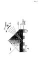
- a diffraction sensor Based on a Kretschmann configuration (cf. Fig.1), a diffraction sensor is provided which allows to monitor the dynamic interaction of biological molecules in a label-free way. According to the invention it is not necessary to provide labels such as fluorescent labels for detecting an analyte. However, mass labels such as latex or Au nanoparticles can be used to further increase the sensitivity.
- the invention is demonstrated by the binding of an anti-biotin antibody to a biotin functionalized region of a periodically patterned surface, which generated significant optical contrast to diffract the surface plasmon field and allows for qualitative detection of an analyte.
- a quadratic dependence of diffraction signal on the amount of bound analyte, e.g. antibody was found, which coincides with the theoretical expectation and allows for quantitative detection of an analyte.
- the finding that the diffraction intensity increases quadratically with the increase of the optical contrast emphasizes the role of the initial contrast in achieving higher sensitivity.
- an aspect ratio i.e. the ratio of functionalized areas containing a receptor for the analyte to non-functionalized or passivated areas preferably is 0.7:1 to 1:0.7, in particular, 0.8:1 to 1:0.8.
- the sensor according to the invention is a surface plasmon field-enhanced diffraction sensor.
- Such sensor comprises a metal substrate, preferably a planar metal substrate.
- Planar metal substrate in particular, means that the metal substrate has an even surface and does not have any surface structures of the metal material, e.g. no surface structures in the form of gratings, recesses or patterns of the metal.
- the metal substrate preferably is made of gold, silver, platinum, palladium, aluminum, nickel, copper, zinc, cadmium and/or mixtures and/or alloys of these metals, in particular, of a noble metal, preferably of gold.
- the metal substrate preferably has a thickness of at least 10 nm, more preferably at least 20 nm and, in particular, at least 40 nm and preferably up to 1 ⁇ m, more preferably up to 200 nm, in particular, up to 100, nm and especially preferably up to 60 nm.
- a metal substrate of gold which has a thickness of approximately 40 nm to 60 nm.
- the metal is arranged and preferably deposited on one side of a prism, which allows to couple light into surface plasmon modes on the metal substrate.
- the prism can be made e.g. of glass, preferably of a material having a high refractive index, such as high RI glass.
- a periodic structure is arranged on the metal substrate.
- Said periodic structure is not produced from metal but is rather formed from organic molecules and, in particular, from biomolecules.
- the metal substrate comprises at least two distinct areas, so-called functional areas or functional regions, comprising a receptor for an analyte. The receptor thereby is capable of binding to the desired analyte.
- the functionalized areas are separated by at least one non-functionalized area. Said separating area or separating region does not comprise the receptor of the functionalized area and, in particular, no receptor which is capable of binding to the desired analyte.
- said separating area is blocked or passivated so that as few as possible and, preferably, no sample constituents can bind in this area.
- the periodic structure of the invention can be of any dimension and comprise, for example, at least three, preferably at least five, more preferably at least ten distinct functionalized areas and, for example, at least two, preferably at least four, more preferably at least nine separating areas. It is essential that the areas are arranged recurrently so as to yield a periodic structure.
- a periodic structure consists of parallel lines, wherein functionalized and non-functionalized lines alternate.
- the periodic structure preferably has a periodicity which is close to or greater than the wavelength of the irradiated light, for example, from 400 nm, in particular, from 1 ⁇ m to 2,000 ⁇ m, in particular, to 1,000 ⁇ m, more preferably from 50 to 200 ⁇ m.
- the aspect ratio i.e. the ratio of functionalized areas to non-functionalized areas, preferably is in the range of from 1:100 to 100:1, more preferably from 5:100 to 2:1 and more preferably from 0.7:1 to 1:0.7. It has been found that the diffracted energy can be concentrated in the first diffraction orders by an aspect ratio which approximates 1:1, i.e., in particular, 0.8:1 to 1:0.8, more preferably 0.9:1 to 1:0.9.
- the receptor can be attached to the metal substrate according to known processes, e.g. by covalent binding, Van der Waals interactions or electrostatic interactions.
- the receptor is preferably applied in diluted form, e.g. at a ratio of 1:5 to 1:20 together with diluting molecules which contain the same binding group for attaching to the metal, however, not the receptor group capable of binding with the analyte.
- the receptor is provided depending on the analyte and comprises, for example, antibodies (e.g. for detecting antigens or proteins), antigens (e.g. for detecting antibodies), nucleic acids (e.g. for detecting nucleic acids), members of a high-affinity binding pair (e.g.
- each receptor group is suitable which binds with the desired analyte, with specific receptors being preferred. While binding to the analyte is desired in the functionalized areas, it is preferred that the non-functionalized areas are such that no sample constituents at all, however, at any rate the desired analyte, does not bind thereto. Therefore, these areas preferably are passivated or blocked.
- the functionalized areas in the periodic structure b) of one sensor contain different receptors for the same analyte
- all functionalized areas of one sensor contain the same receptor and, in particular, the same amount of the same receptor, to produce a biological pattern for enhancing diffraction.
- the same receptor is used each, it is possible according to the invention to provide sensors, by means of which several different analytes can be detected using several periodic structures b) or which contain different receptors for the same analyte in different periodic structures b).
- Sensors which have an array structure preferably comprise at least two, more preferably at least five, even more preferably at least ten periodic structures b), whereby according to the invention each of these periodic structures is designed for the detection of a single analyte, and the different periodic structures each comprise different receptors, e.g. different receptors for the same analyte, or preferably different receptors for different analytes.
- the sensor of the invention further comprises a light source.
- a light source By means of said light source light is irradiated onto the metal substrate on the opposite side of the periodic structure of b), i.e. to the reverse side of the metal substrate through a coupling prism for SPR coupling.
- the light source is a laser, e.g. an infrared laser such as an HeNe laser.
- the sensor of the invention comprises means for detecting light, preferably an optical detector such as a photodiode or a photodiode array. The light reflected from the metal substrate, which is reflected on the side of the metal substrate opposite the periodic structure, is measured by means of the detector.
- suitable devices e.g. a slit, the resolution of the detection device can be determined and improved, respectively.
- Another subject matter of the invention is a sensor having the analyte bound to the receptor in the periodic structure.
- the metal substrate preferably is applied onto a material having high refractive index.
- the metal substrate is applied onto a prism, whereby the prism is arranged on the opposite side of the periodic structure of receptors.
- the analyte is applied in a liquid sample, e.g. in an aqueous solution.
- the sensor of the invention is provided with a flow cell which enables continuous supply of analyte solution.
- the sensor of the invention is based on a concept of using functional pattern layer on a metal surface to diffract the surface plasmon electromagnetic field supported by the metal surface and thereby achieving bio-sensing with high performance.
- the sensor of the invention uses a couple-out phenomenon from the surface plasmons to normal light (free radiation).
- the arrangement of the invention allows self-referencing as well as quadratic signal amplification.
- the invention also comprises an array which comprises at least two, more preferably at least five, even more preferably at least ten sensors of the invention. While it is possible to provide complete sensors each, it is also possible to form an array, wherein several sensors, for example, share the means for emitting light and/or means for detecting light.
- the invention further provides the above-described sample holder which comprises the metal substrate applied onto a prism, and the periodic structure of receptors present thereon. Such sample holder then can be integrated into a conventional surface plasmon resonance apparatus.
- the invention further comprises a process for producing a surface plasmon field-enhanced diffraction sensor comprising the steps:
- a periodic structure on a metal substrate can be produced by micro-contact printing ( ⁇ CP). Binding of the receptor onto the metal surface can be effected by conventional binding mechanisms, e.g. by covalent binding, Van der Waals interaction or electrostatic interaction.
- the separating areas are preferably passivated, e.g. by coating them with a blocking solution.
- a suitable blocking solution for example, is a solution of the dilution molecules having the binding group for binding with the metal surface group, however, not a receptor group for binding to the analyte.
- the sensor of the invention is suitable both for qualitative and quantitative detection of analytes as well as for kinetic tests. It is not necessary thereby to provide the analyte or other sample constituents with a label or marker, e.g. a fluorescent marker or a dye marker. Binding the analyte to the receptor pattern and measuring the reflected/diffracted light enables direct measurement of the analyte. Particularly good results are obtained, if diffracted light is measured, especially diffracted light of first, second, third, fourth or fifth order, in particular, of first or second order.
- a label or marker e.g. a fluorescent marker or a dye marker.
- Another advantage of the sensor of the invention is that it can be regenerated as often as desired and without substantial efforts and, thus, can be used for new measurements over and over again.
- a regenerated sensor is obtained which then can be used again for further analyses.
- the ATR-based diffraction mode also allows for the observation of holographic information stored in the region of the interfacial evanescent optical field.
- the localized PSP wave can be diffracted by gaining (or losing) discrete momenta m.g,which is generated by the periodic surface structure of periodicity ⁇ .
- k m diff k PSP ⁇ mg
- k m / diff the wavevector of the mth diffraction order
- k PSP the wavevector the PSP wave
- m the diffraction order.
- the diffraction intensity I d can be approximated by the following expression: 12 I d ⁇ I 0 ⁇ ⁇ nd ⁇ 2 where I 0 and ⁇ are the intensity and wavelength of the source field respectively, ⁇ nd represents the grating amplitude in an optical thickness format.
- I 0 and ⁇ are the intensity and wavelength of the source field respectively
- ⁇ nd represents the grating amplitude in an optical thickness format.
- This equation conveys two important messages: 1.
- the diffraction intensity I d is proportional to the intensity of the excitation source - the evanescent field, which emphasizes the importance of the surface plasmon field enhancement.
- I d is proportional to the square of the grating amplitude ⁇ nd .
- the diffraction pattern is a Fourier transformation of the source pattern, which can assist a proper grating design.
- patterns of repeating parallel lines were applied represented by square-wave functions.
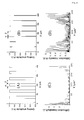
- a symmetric pattern with ⁇ closer to 1 concentrates the diffracted intensity at the first several diffraction orders (cf. Figure 2(C)), as it resembles a sinusoidal grating and contains less frequency artifacts.
- the diffraction orders are evenly distributed (cf. Figure 2(D)), with the intensity being significantly reduced. Therefore, a symmetric grating pattern renders higher diffraction intensity, which generally meets the sensing demand.
- the sensor according to the invention in particular an immuno-sensor is based on the diffraction of surface plasmon, which allows for in-situ, real-time and label-free observation of interfacial binding events.
- the inherent self-referencing mechanism of surface diffraction is found to be very effective for compensating fluctuations of the bulk, demonstrated by a temperature variation experiment.
- Possessing stable baseline signal, the diffraction sensor offers high sensitivity, e.g. pico-molar sensitivity in directly detecting the binding of human chorionic gonadotropin (hCG) hormone.
- Another important advantage of the sensor according to the invention is its self-referencing mechanism.
- the diffraction sensor For the diffraction sensor, functional patterns on the sensor surfaces are created, e.g. by using micro-patterning technique. Preferably, the remaining areas are completely passivated, e.g. by a coating that is resistant to the binding of biomolecules (e.g., a self-assembled monolayer (SAM) of oligoethylene-glycol (OEG) terminated thiols).
- SAM self-assembled monolayer
- OEG oligoethylene-glycol
- the binding occurring specifically to the functional zone modulates the optical contrast of the 'dynamic biological grating', inducing a change of the diffraction efficiency.
- bulk effects simultaneously influence both functional and non-functional areas, and, hence, are largely compensated. Therefore, in theory, the diffraction-based sensor according to the invention is inherently 'self-referencing'.
- special features in SPR-based diffraction sensor are additionally taken into account. Since the incident angle of the laser is kept constant for surface plasmon excitation, any bulk effect can influence the diffraction intensity by shifting the surface plasmon minimum angle, thus de-tuning the coupling efficiency of the light to the surface plasmon mode. Therefore, practically it is preferred to fix the incident light at an angle so that a certain shift of the SPR spectrum will have a minimum impact on the plasmon field intensity.
- the sensor according to the invention further enables the detection of nucleic acid molecules.
- the detection and analysis of genetic material has drawn unprecedented research efforts during the past decades due to the increasing interest arising from both application and fundamental research concerns.
- Many methods for the label-free detection of oligonucleotide DNA binding through base pairing have been reported based on optical 20,21 , electrochemical 22 and piezoelectric 23 , nanomechanical 24 techniques.
- the basis of operation for a DNA sensor is the coupling between a specific base sequence within a DNA target analyte and the complementary oligonucleotide sequence immobilized on the solid surface of a transducer substrate. This DNA hybridization can be detected as a physical signal and can be monitored in-situ and in real-time.
- the novel biosensor according to the invention i.e. a surface plasmon diffraction sensor (SPDS), based on surface-plasmon-enhanced diffraction phenomena at periodic spatial structures a highly sensitive and robust sensing technique is provided.
- SPDS surface plasmon diffraction sensor
- the surface grating structure produced by a biological grating, preferably by the analyte itself, can diffract the incident light by superimposing discrete momenta m ⁇ g (with
- 2 ⁇ / ⁇ being the magnitude of grating vector, m being the order of diffraction) generated by the grating constant A (cf. Figure 1).
- the high optical intensity of the surface-plasmon field greatly enhances the diffraction efficiency of the incident light and allows for a very sensitive probing of surface heterogeneities.
- the modulation of the grating amplitude upon a biological interaction event induces a quadratically amplified change of the diffraction intensity.
- the temperature fluctuations and other bulk effects are automatically compensated during the sensing process, due to the inherently 'self-referencing' property of SPDS. Therefore, SPDS is an attractive method for detecting and characterizing oligonucleotide hybridization processes.
- streptavidin monolayer is formed on a mixed self-assembled monolayer (SAM) exposing 5-10% biotin functionalities.
- SAM mixed self-assembled monolayer
- the remaining biotin-binding pockets (approx. 1-2) in the surface-attached streptavidin allow for a subsequent attachment of biotinylated DNA probes, with the size of the streptavidin providing a natural limitation of the probe surface density for the next interaction step - the target hybridization.
- biotin thiol- and oligo-ethylene-glycol (OEG) thiol- (spacer thiol) derivatives used are given in Figure 3A.
- Mouse anti-biotin monoclonal antibody 2F5 and biotinylated rabbit anti-goat antibody (abbreviated as biotin-RaG, with 5.2 biotin groups per IgG) was purchased from Molecular Probes.
- D-biotin and guanidine hydrochloride was purchased from Sigma.
- HBS-EP buffer degassed 10 mM HEPES buffer saline, pH 7.4, 150 mM NaCl, 3 mM EDTA, 0.005% (v/v) surfactant P-20, Biacore, Uppsala, Sweden
- P-20 degassed 10 mM HEPES buffer saline, pH 7.4, 150 mM NaCl, 3 mM EDTA, 0.005% (v/v) surfactant P-20, Biacore, Uppsala, Sweden
- HCG human chorionic gonadotropin
- BSA bovine serum albumin
- Glycine/HCl buffer (10 mM, pH 1.7) was obtained from Biacore.
- the biotinylated DNA probe and DNA targets were purchased from MWG-biotech, and are also listed in Table 1.
- the 75-mer targets consist of the same recognition sequences as the 15-mer targets (T15-0, T15-1), however, have two flanks of poly T (30-mer).
- the T15-0 and T75-0 are fully complementary to the DNA probe, i.e., they define a mismatch zero (MM0) situation, while one base mismatch (MM1) was designed in the sequences of T15-1 and T75-1, respectively.
- a two-base mismatch (MM2) was designed for the T15-2 target.
- Streptavidin (SA) was also kindly provided by Roche Diagnostics.
- HBS-EP buffer degassed 10 mM HEPES buffer saline, pH 7.4, 150 mM NaCl, 3 mM EDTA, 0.005% (v/v) surfactant P-20, Biacore, Uppsala, Sweden
- P-20 degassed 10 mM HEPES buffer saline, pH 7.4, 150 mM NaCl, 3 mM EDTA, 0.005% (v/v) surfactant P-20, Biacore, Uppsala, Sweden
- PDMS stamps with embossed lines were prepared using Sylgard 184 silicon elastomer (Dow Corning).
- the stamp was inked for 5 minutes in an ethanolic solution of the mixed biotin and spacer thiol (molar ratio 1:9) (cf. Example 1) with a net concentration of 0.5 mM. Excess thiol solution was removed and the stamp was dried in a flow of nitrogen.
- the stamp was then brought into contact with a freshly evaporated Au (50 nm) substrate for a period of 1-1.5 minutes.
- the patterned substrate was rinsed with ethanol and dried in a flow of nitrogen.
- An 'un-patterned' surface herein means a surface completely covered by a mixed self-assembled monolayer (SAM) composed of biotin and spacer thiol with molar ratio of 1:9 unless otherwise mentioned.
- SAM mixed self-assembled monolayer
- the diffraction experiments was based on a Kretschmann surface plasmon resonance spectroscopy (SPR or SPS) set-up which has been described in detail by Yu et al. 13
- a schematic drawing is shown in Fig.1.
- the reflected/diffracted light at an angle ⁇ was measured by a photodiode detector connected to a lock-in amplifier.
- the angular acceptance ⁇ of the detector was ⁇ 0.08°, which was limited by a 1 mm slit.
- the sample (prism, Au substrate and flow cell) and the detector were mounted to two co-axial goniometers, respectively, enabling an independent tuning of the incident angle ⁇ of the laser and/or the detection angle ⁇ .
- Both motors rotated in a ⁇ /2 ⁇ fashion for the SPR angular scan.
- the detector motor rotated ( I d -versus- ⁇ , cf. Figure 1) while the sample motor kept static at the SPR minimum angle.
- SPM Surface plasmon microscopy
- a glass flow cell was coupled to the set-up and a peristaltic pump delivered the sample liquid at a flow rate of 3 mL/min.
- a peristaltic pump delivered the sample solutions at a flow-rate of 3 mL/min, in order to alleviate the mass-transport effect for a correct assessment of the binding kinetics.
- the solutions were circulated in a sealed tubing loop after being manually exchanged, a procedure that is especially advantageous if equilibrium titration experiments are conducted.
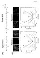
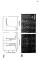
- the optical contrasts of the both patterned surfaces were originated from the 10% biotin thiol (slightly larger than the spacer thiol), which were insufficient to render measurable diffractions (cf. full triangles in Figure 4). Subsequently, significant diffractions were observed upon exposing the surfaces to the antibody solution (cf. full curves in Figure 4).
- pattern A the first two observable diffraction orders had more pronounced intensities, in agreement with the simulation for a symmetric pattern (cf. Figure 2(C)).
- pattern B the diffraction intensity was more evenly distributed, also in agreement with the simulation for an asymmetric pattern (cf. Figure 2(D)).
- the bound antibodies could be completely denatured and removed from the surface by a pulse injection ( ⁇ 5 minutes) of a 4 M aqueous guanidine hydrochloride solution. The removing of the antibody reset the diffraction pattern to the original level (cf. open triangles in Figure 4).
- Another injection of the anti-biotin antibody resulted in identical diffraction signals, which suggests the surfaces were as ⁇ 100% functional as pre-regeneration.
- the patterned surfaces were highly robust to sustain the regeneration condition for many times.
- the diffraction intensity could be monitored as a function of time, realizing a kinetic observation of biomolecular bindings.
- the incident light was set at the SPR minimum ⁇ 0 to generate strong PSP field.
- the detector arm was tuned to the angle of the first observable diffraction peak (cf. dashed line in Figure 4). Having a larger biotin area, pattern A surface could give significant SPR and diffraction signal upon the antibody binding, and then a relationship between both signals could be established.
- the working concentration of the anti-biotin solution was 5 nM, in order to realize a mass-transport limited binding.
- the antibody binding could be paused for quantitative SPR/diffraction angular scans by manipulating, e.g., the flow rate of the sample delivering.
- the following steps were performed at each point indicated in Figure 5(B) by an arrow:
- the aforementioned binding/desorbing/competitive desorbing process was performed on the pattern A and B surfaces, monitored by the diffraction kinetic mode.
- a SPR angular curve was firstly recorded.
- the incident angle of the laser was then fixed at the SPR minimum angle, in order to couple ⁇ 100% light intensity to the Au/dielectric interface and to thus obtain maximum diffraction intensity and to minimize the angular "detuning" effect.
- FIG. 7(A) shows the left panel shows the diffraction patterns before and after the antibody binding (full and dotted curve, respectively), the right curve shows the time dependent increase of the intensity of the monitored diffraction order.
- Figure 7(B) shows the SPM characterization of the patterned surface: before the binding of the anti-biotin antibody (left picture), the image was nearly featureless corresponding to the weak diffraction intensity. However, after the binding (right picture), a clear surface pattern emerged which was the replica of the pattern of the stamp.
- I d A*( ⁇ nd ) 2
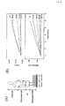
- Figure 8 (B) shows the corresponding SPR and diffraction responses, respectively, as a function of time recorded after injection of different concentrations of 2F5 (50 pM, 100 pM, 400 pM, 750 pM, 1 nM, respectively) on the same sensor surface.
- the SPR response was measured by tuning the laser incident to an angle slightly smaller than the SPR minimum angle and monitoring the reflectivity change of the reflected laser beam (i.e., the 0th diffraction order).
- the anti-biotin antibodies could be completely removed from the surface by a pulse injection of glycine buffer (10 mM, pH 1.7), without damaging the strong biotin-SA linkages underneath, as indicated by a stable baseline level.
- Typical angular diffraction scans are shown schematically in Figure 1, representing the diffraction patterns before and after the binding of, e.g., a DNA target.
- the proportional increase in the diffraction intensity (DI) for every diffraction order indicates an optical thickness increase occurring at the surface of the functional regions.
- the intensity of each diffraction order depends strongly on the laser incident angle ⁇ , which determines the surface plasmon coupling efficiency, as shown in the inset of Figure 1.
- the maximum diffraction intensity of the monitored diffraction order ( ⁇ 0 ) appears at the SPR minimum angle ⁇ 0 .
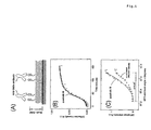
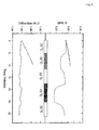
- FIG. 12(A) The schematic drawing of the employed multi-layer architecture composed of SAM/streptavidin/probe/target is shown in Figure 12(A).
- the processes were recorded as the sequential increases of the diffraction signal as shown in Figure 12(B).
- exposing the patterned surface to a 1 ⁇ M SA solution lead to a quick increase of the diffraction signal followed by a second slower increasing phase.
- the second phase is considered to be associated with a non-specific aggregation of SA molecules because a pure buffer rinse could gradually wash away the signal accumulated in that phase.
- the baseline remained at approx. 0.48 mV and was extremely stable.
- ⁇ nd is the amplitude of the biological grating represented by the optical thickness
- I o and ⁇ are the intensity and wavelength of the light source, respectively.
- I b can be obtained from a measurement on an un-patterned gold surface, and is typically found to be ⁇ 0.01 mV. Therefore, ⁇ I d - I b gives the increment of the corrected diffraction signal that is considered to be a response linear to the optical thickness of each layer, which in return is a linear function of the mass concentration of the bound biomolecules.
- ⁇ I d - I b divided by the corresponding molecular weight (Mw) provides the relative molar surface concentration, and can be used to calculate the stoichiometry between interacting molecules.
- Mw molecular weight
- the extra two poly-T flanks for the 75-mers play a major role in decreasing the HE, owing to the steric/electrostatic hindrance.
- the longer extension of the hybridized 75-mers away from the surface may slightly lower their contribution to the optical thickness change sensed by the surface plasmon evanescent field, which decays exponentially into the solution with a depth of L z ⁇ 150 nm.
- the one-base mismatch induced an apparent difference in the binding curves between T15-0 and T15-1, T75-0 and T75-1, especially in the dissociation phases.
- the obtained K A values differed by more than an order of magnitude between the 15-mers (4.98x10 8 M -1 , 2.18x10 7 M -1 for T15-0, T15-1 respectively) and the 75-mers (2.62x10 8 M -1 , 1.46x10 7 M -1 for T75-0, T75-1 respectively).
- a mismatch-two sequence T15-2 was also tested, however, yielded a negligible binding signal. This demonstrated that the obtained hybridization signals were highly specific and the sensor was sensitive to a single-base-pair mismatch.
- the affinity constants K A of the 15-mers were also determined by recording the equilibrium binding to the probe surface at different bulk target concentrations c 0 . Total span of the target concentration was from 1 nM to 3 ⁇ M. The normalized equilibrium response was plotted against the corresponding concentrations co, as shown in Figure 4.
- a non-linear steady-state fit, based on Langmuir 1:1 model, allows for the determination of K A , according to: ⁇ K A c 0 1+ K A c 0 with ⁇ being the normalized response (surface coverage), and c 0 the bulk concentration.
- the affinity constants for T15-0 and T15-1 were 4.17x10 8 M -1 and 1.92x10 7 M -1 , respectively, in good agreement with the affinity constants obtained from the single association/dissociation study. This implies that, the Langmuir model can be applied for the parametrization of the hybridization processes of the 15-mers.
- the probe density plays an important role in the target surface hybridization behaviors, i.e., for the binding kinetics and the hybridization efficiency.
- the hybridization experiments using 15-mer oligonucleotide targets at a concentration of 2 ⁇ M were performed at each level of probe density.
- the high target concentration was used to ensure the (almost) saturated occupation of the available hybridization sites (cf. Figure 4).
- the end-point hybridization signals reached at association equilibrium were corrected, considering the quadratic effect of the diffraction sensor.
- the HEs were quantified and plotted in Figure 15(B). One can see that the HE of both targets increased with the probe coverage decreasing. This can be explained by the alleviation of the static and/or electrostatic barrier on diluted probe surfaces.
- the HE value of T15-0 reached ⁇ 96%, indicating that the surface was (nearly) totally functional which can be attributed to the good orientation and moderate density built on the SAM/SA supra-architecture.
- An interesting observation is that the highest HE of the T15-1 target was only ⁇ 85% even at the lowest probe density studied, although operating at a saturation concentration. This implies a reduced availability of sites for MM1 target hybridization by a higher hybridization barrier due to the internally mismatched base.
- the difference in HE ( ⁇ HE, cf. Figure 15) between the MM0 and MM1 targets could only be slightly alleviated by lowering the probe density.
- SPDS has been successfully applied for direct and rapid detection of oligonucleotides based on an efficient SAM/SA/probe architecture. It is also a well-qualified tool to discriminate single base-pair mismatch of oligonucleotides by monitoring their kinetic behaviors in real-time. Affinity constants for the 15-mers using both kinetics measurements and equilibrium titration were obtained. The strong dependence of the HE was also studied by controlling the probe density on the sensor surface. Substantial improvements of the HE were achieved when lowering the probe density, although the absolute amount of hybridized targets decreased. A three-dimensional surface matrix may both favor the amount and the efficiency of the hybridization in practical applications.
- High quality interaction assays can be offered by SPDS, attributed to its self-referencing property.
- the binding curves are free of any artifacts from the sample exchange in Figure 15(A), which generally exists in many optical biosensors and significantly influences the precise quantification of small binding signals.
- the limit of detection was -800 pg/mm 2 from a rather preliminary assessment, which already compares favorably to many (commercially) available label-free methods.
- the concept of the diffraction detection offers a novel way to integrate reference channels in the micro-array fabrication, which improves the stability and sensitivity of large-scale label-free screening applications.
Landscapes
- Chemical & Material Sciences (AREA)
- Engineering & Computer Science (AREA)
- Nanotechnology (AREA)
- Physics & Mathematics (AREA)
- Health & Medical Sciences (AREA)
- Life Sciences & Earth Sciences (AREA)
- General Health & Medical Sciences (AREA)
- General Physics & Mathematics (AREA)
- Immunology (AREA)
- Pathology (AREA)
- Biochemistry (AREA)
- Crystallography & Structural Chemistry (AREA)
- Analytical Chemistry (AREA)
- Composite Materials (AREA)
- Condensed Matter Physics & Semiconductors (AREA)
- Materials Engineering (AREA)
- Molecular Biology (AREA)
- Investigating Or Analysing Materials By Optical Means (AREA)
Priority Applications (1)
| Application Number | Priority Date | Filing Date | Title |
|---|---|---|---|
| EP05003435A EP1566627A1 (de) | 2004-02-18 | 2005-02-17 | Feldverstärkter Oberfächenplasmonenresonanzbeugungssensor |
Applications Claiming Priority (3)
| Application Number | Priority Date | Filing Date | Title |
|---|---|---|---|
| EP04003665 | 2004-02-18 | ||
| EP04003665 | 2004-02-18 | ||
| EP05003435A EP1566627A1 (de) | 2004-02-18 | 2005-02-17 | Feldverstärkter Oberfächenplasmonenresonanzbeugungssensor |
Publications (1)
| Publication Number | Publication Date |
|---|---|
| EP1566627A1 true EP1566627A1 (de) | 2005-08-24 |
Family
ID=34712596
Family Applications (1)
| Application Number | Title | Priority Date | Filing Date |
|---|---|---|---|
| EP05003435A Withdrawn EP1566627A1 (de) | 2004-02-18 | 2005-02-17 | Feldverstärkter Oberfächenplasmonenresonanzbeugungssensor |
Country Status (1)
| Country | Link |
|---|---|
| EP (1) | EP1566627A1 (de) |
Cited By (12)
| Publication number | Priority date | Publication date | Assignee | Title |
|---|---|---|---|---|
| US7091049B2 (en) | 2002-06-26 | 2006-08-15 | Kimberly-Clark Worldwide, Inc. | Enhanced diffraction-based biosensor devices |
| US7118855B2 (en) | 2002-05-03 | 2006-10-10 | Kimberly-Clark Worldwide, Inc. | Diffraction-based diagnostic devices |
| US7169550B2 (en) | 2002-09-26 | 2007-01-30 | Kimberly-Clark Worldwide, Inc. | Diffraction-based diagnostic devices |
| US7214530B2 (en) | 2002-05-03 | 2007-05-08 | Kimberly-Clark Worldwide, Inc. | Biomolecule diagnostic devices and method for producing biomolecule diagnostic devices |
| US7223534B2 (en) | 2002-05-03 | 2007-05-29 | Kimberly-Clark Worldwide, Inc. | Diffraction-based diagnostic devices |
| US7223368B2 (en) | 2002-05-03 | 2007-05-29 | Kimberly-Clark Worldwide, Inc. | Diffraction-based diagnostic devices |
| US7485453B2 (en) | 2002-05-03 | 2009-02-03 | Kimberly-Clark Worldwide, Inc. | Diffraction-based diagnostic devices |
| US7771922B2 (en) | 2002-05-03 | 2010-08-10 | Kimberly-Clark Worldwide, Inc. | Biomolecule diagnostic device |
| US7884940B2 (en) | 2005-11-16 | 2011-02-08 | Mivitec Gmbh | Distributed measurement spots and reference spots, especially for chemosensors and biosensors |
| WO2014003529A3 (fr) * | 2012-06-28 | 2014-02-27 | Moroccan Foundation For Advanced Science, Innovation & Research (Mascir) | Design d'un capteur à haute performance à base de modes optiques guides dans une micro puce à structure periodique de milieux dielectriques |
| WO2019194166A1 (ja) * | 2018-04-04 | 2019-10-10 | 国立大学法人東京大学 | Sprセンサチップ、sprセンサ、及び試料の解析方法 |
| EP3707537A4 (de) * | 2017-11-06 | 2021-08-11 | Xfold Imaging Oy | Feldverstärkungsvorrichtung |
Citations (4)
| Publication number | Priority date | Publication date | Assignee | Title |
|---|---|---|---|---|
| US4931384A (en) * | 1982-12-21 | 1990-06-05 | Ares-Serono N.V. | Optical assay technique |
| US5442448A (en) * | 1993-03-27 | 1995-08-15 | Boehringer Mannheim Gmbh | Device for the laterally resolved investigation of a laterally heterogeneous ultrathin object layer |
| US5986762A (en) * | 1998-06-15 | 1999-11-16 | Imation Corp. | Optical sensor having optimized surface profile |
| WO2003014711A1 (en) * | 2001-08-07 | 2003-02-20 | Mitsubishi Chemical Corporation | Surface plasmon resonance sensor chip, and sample analysis method and analysis apparatus using the same |
-
2005
- 2005-02-17 EP EP05003435A patent/EP1566627A1/de not_active Withdrawn
Patent Citations (5)
| Publication number | Priority date | Publication date | Assignee | Title |
|---|---|---|---|---|
| US4931384A (en) * | 1982-12-21 | 1990-06-05 | Ares-Serono N.V. | Optical assay technique |
| US5442448A (en) * | 1993-03-27 | 1995-08-15 | Boehringer Mannheim Gmbh | Device for the laterally resolved investigation of a laterally heterogeneous ultrathin object layer |
| US5986762A (en) * | 1998-06-15 | 1999-11-16 | Imation Corp. | Optical sensor having optimized surface profile |
| WO2003014711A1 (en) * | 2001-08-07 | 2003-02-20 | Mitsubishi Chemical Corporation | Surface plasmon resonance sensor chip, and sample analysis method and analysis apparatus using the same |
| EP1424549A1 (de) * | 2001-08-07 | 2004-06-02 | Mitsubishi Chemical Corporation | Oberflächenplasmonresonanz-sensorchip sowie diesen verwendendes probenanalyseverfahren und analysegerät |
Non-Patent Citations (6)
| Title |
|---|
| ANGELEY D G: "Optical transduction technique utilizing gratings with a potential application towards biosensing", PROCEEDINGS OF THE SPIE - THE INTERNATIONAL SOCIETY FOR OPTICAL ENGINEERING SPIE-INT. SOC. OPT. ENG USA, vol. 4958, 2003, pages 1 - 12, XP002330601, ISSN: 0277-786X * |
| MORHARD F ET AL: "Immobilization of antibodies in micropatterns for cell detection by optical diffraction", SENSORS AND ACTUATORS B, ELSEVIER SEQUOIA S.A., LAUSANNE, CH, vol. 70, no. 1-3, 1 November 2000 (2000-11-01), pages 232 - 242, XP004224604, ISSN: 0925-4005 * |
| ROTHENHAUSLER B ET AL: "TOTAL INTERNAL DIFFRACTION OF PLASMON SURFACE POLARITONS", APPLIED PHYSICS LETTERS, AMERICAN INSTITUTE OF PHYSICS. NEW YORK, US, vol. 51, no. 11, 14 September 1987 (1987-09-14), pages 723 - 785, XP000021814, ISSN: 0003-6951 * |
| YU F ET AL: "IMMUNOSENSOR WITH SELF-REFERENCING BASED ON SURFACE PLASMON DIFFRACTION", ANALYTICAL CHEMISTRY, AMERICAN CHEMICAL SOCIETY. COLUMBUS, US, vol. 76, no. 7, 1 April 2004 (2004-04-01), pages 1971 - 1975, XP001196731, ISSN: 0003-2700 * |
| YU F ET AL: "SURFACE PLASMON ENHANCED DIFFRACTION FOR LABEL-FREE BIOSENSING", ANALYTICAL CHEMISTRY, AMERICAN CHEMICAL SOCIETY. COLUMBUS, US, vol. 76, no. 13, 1 July 2004 (2004-07-01), pages 3530 - 3535, XP001209786, ISSN: 0003-2700 * |
| YU FANG ET AL: "Oligonucleotide hybridization studied by a surface plasmon diffraction sensor (SPDS).", NUCLEIC ACIDS RESEARCH. 2004, vol. 32, no. 9, 20 May 2004 (2004-05-20), pages E75.1 - E75.7, XP002330600, ISSN: 1362-4962, Retrieved from the Internet <URL:http://nar.oxfordjournals.org/cgi/content/full/32/9/e75> [retrieved on 20050602] * |
Cited By (15)
| Publication number | Priority date | Publication date | Assignee | Title |
|---|---|---|---|---|
| US7485453B2 (en) | 2002-05-03 | 2009-02-03 | Kimberly-Clark Worldwide, Inc. | Diffraction-based diagnostic devices |
| US8110349B2 (en) | 2002-05-03 | 2012-02-07 | Kimberly-Clark Worldwide, Inc. | Method for producing biomolecule diagnostic devices |
| US7695979B2 (en) | 2002-05-03 | 2010-04-13 | Kimberly-Clark Worldwide, Inc. | Biomolecule diagnostic devices |
| US7214530B2 (en) | 2002-05-03 | 2007-05-08 | Kimberly-Clark Worldwide, Inc. | Biomolecule diagnostic devices and method for producing biomolecule diagnostic devices |
| US7223534B2 (en) | 2002-05-03 | 2007-05-29 | Kimberly-Clark Worldwide, Inc. | Diffraction-based diagnostic devices |
| US7223368B2 (en) | 2002-05-03 | 2007-05-29 | Kimberly-Clark Worldwide, Inc. | Diffraction-based diagnostic devices |
| US7118855B2 (en) | 2002-05-03 | 2006-10-10 | Kimberly-Clark Worldwide, Inc. | Diffraction-based diagnostic devices |
| US7771922B2 (en) | 2002-05-03 | 2010-08-10 | Kimberly-Clark Worldwide, Inc. | Biomolecule diagnostic device |
| US7091049B2 (en) | 2002-06-26 | 2006-08-15 | Kimberly-Clark Worldwide, Inc. | Enhanced diffraction-based biosensor devices |
| US7169550B2 (en) | 2002-09-26 | 2007-01-30 | Kimberly-Clark Worldwide, Inc. | Diffraction-based diagnostic devices |
| US7884940B2 (en) | 2005-11-16 | 2011-02-08 | Mivitec Gmbh | Distributed measurement spots and reference spots, especially for chemosensors and biosensors |
| WO2014003529A3 (fr) * | 2012-06-28 | 2014-02-27 | Moroccan Foundation For Advanced Science, Innovation & Research (Mascir) | Design d'un capteur à haute performance à base de modes optiques guides dans une micro puce à structure periodique de milieux dielectriques |
| EP3707537A4 (de) * | 2017-11-06 | 2021-08-11 | Xfold Imaging Oy | Feldverstärkungsvorrichtung |
| WO2019194166A1 (ja) * | 2018-04-04 | 2019-10-10 | 国立大学法人東京大学 | Sprセンサチップ、sprセンサ、及び試料の解析方法 |
| JP2019184314A (ja) * | 2018-04-04 | 2019-10-24 | 国立大学法人 東京大学 | Sprセンサチップ、sprセンサ、及び試料の解析方法 |
Similar Documents
| Publication | Publication Date | Title |
|---|---|---|
| Campbell et al. | SPR microscopy and its applications to high-throughput analyses of biomolecular binding events and their kinetics | |
| Shumaker-Parry et al. | Quantitative methods for spatially resolved adsorption/desorption measurements in real time by surface plasmon resonance microscopy | |
| Knoll et al. | Streptavidin arrays as supramolecular architectures in surface-plasmon optical sensor formats | |
| Jordan et al. | Surface plasmon resonance imaging measurements of DNA hybridization adsorption and streptavidin/DNA multilayer formation at chemically modified gold surfaces | |
| Schasfoort | Introduction to surface plasmon resonance | |
| Wijaya et al. | Surface plasmon resonance-based biosensors: From the development of different SPR structures to novel surface functionalization strategies | |
| Piliarik et al. | A new surface plasmon resonance sensor for high-throughput screening applications | |
| Busse et al. | Sensitivity studies for specific binding reactions using the biotin/streptavidin system by evanescent optical methods | |
| Dostálek et al. | Surface plasmon resonance sensor based on an array of diffraction gratings for highly parallelized observation of biomolecular interactions | |
| Piliarik et al. | Towards parallelized surface plasmon resonance sensor platform for sensitive detection of oligonucleotides | |
| Hoa et al. | Enhanced SPR response from patterned immobilization of surface bioreceptors on nano-gratings | |
| Kambhampati et al. | Surface-plasmon optical techniques | |
| US20060197952A1 (en) | Surface plasmon resonance sensor with high sensitivity | |
| Paulo et al. | Tip-specific functionalization of gold nanorods for plasmonic biosensing: effect of linker chain length | |
| JPH10307141A (ja) | プラズモン共鳴および蛍光検出を用いた生体分子相互作用の同時検出法 | |
| Yu et al. | Surface plasmon enhanced diffraction for label-free biosensing | |
| Sun | Optical biosensors for label-free detection of biomolecular interactions | |
| Hill et al. | Nanoparticle–film plasmon ruler interrogated with transmission visible spectroscopy | |
| Gao et al. | Detection of tumor markers based on extinction spectra of visible light passing through gold nanoholes | |
| Wang et al. | Poly (acrylic acid) brushes pattern as a 3D functional biosensor surface for microchips | |
| US20030219809A1 (en) | Surface plasmon resonance shifting interferometry imaging system for biomolecular interaction analysis | |
| Bae et al. | Detection of insulin–antibody binding on a solid surface using imaging ellipsometry | |
| Yu et al. | Immunosensor with self-referencing based on surface plasmon diffraction | |
| US20060194346A1 (en) | Surface plasmon-field-enhanced diffraction sensor | |
| Chen et al. | Near-infrared surface plasmon resonance sensor with a graphene-gold surface architecture for ultra-sensitive biodetection |
Legal Events
| Date | Code | Title | Description |
|---|---|---|---|
| PUAI | Public reference made under article 153(3) epc to a published international application that has entered the european phase |
Free format text: ORIGINAL CODE: 0009012 |
|
| AK | Designated contracting states |
Kind code of ref document: A1 Designated state(s): AT BE BG CH CY CZ DE DK EE ES FI FR GB GR HU IE IS IT LI LT LU MC NL PL PT RO SE SI SK TR |
|
| AX | Request for extension of the european patent |
Extension state: AL BA HR LV MK YU |
|
| 17P | Request for examination filed |
Effective date: 20060111 |
|
| AKX | Designation fees paid |
Designated state(s): AT BE BG CH CY CZ DE DK EE ES FI FR GB GR HU IE IS IT LI LT LU MC NL PL PT RO SE SI SK TR |
|
| 17Q | First examination report despatched |
Effective date: 20080204 |
|
| RAP3 | Party data changed (applicant data changed or rights of an application transferred) |
Owner name: MAX-PLANCK-GESELLSCHAFT ZUR FOERDERUNG DER WISSENS |
|
| STAA | Information on the status of an ep patent application or granted ep patent |
Free format text: STATUS: THE APPLICATION IS DEEMED TO BE WITHDRAWN |
|
| 18D | Application deemed to be withdrawn |
Effective date: 20080815 |