EP1566902A1 - Procédé de transmission d'énergie utilisant des rayons électromagnétiques cohérents - Google Patents
Procédé de transmission d'énergie utilisant des rayons électromagnétiques cohérents Download PDFInfo
- Publication number
- EP1566902A1 EP1566902A1 EP05000093A EP05000093A EP1566902A1 EP 1566902 A1 EP1566902 A1 EP 1566902A1 EP 05000093 A EP05000093 A EP 05000093A EP 05000093 A EP05000093 A EP 05000093A EP 1566902 A1 EP1566902 A1 EP 1566902A1
- Authority
- EP
- European Patent Office
- Prior art keywords
- laser beam
- unit
- receiver
- transmitting unit
- alignment
- Prior art date
- Legal status (The legal status is an assumption and is not a legal conclusion. Google has not performed a legal analysis and makes no representation as to the accuracy of the status listed.)
- Granted
Links
Images




Classifications
-
- H—ELECTRICITY
- H04—ELECTRIC COMMUNICATION TECHNIQUE
- H04B—TRANSMISSION
- H04B10/00—Transmission systems employing electromagnetic waves other than radio-waves, e.g. infrared, visible or ultraviolet light, or employing corpuscular radiation, e.g. quantum communication
- H04B10/80—Optical aspects relating to the use of optical transmission for specific applications, not provided for in groups H04B10/03 - H04B10/70, e.g. optical power feeding or optical transmission through water
- H04B10/806—Arrangements for feeding power
-
- B—PERFORMING OPERATIONS; TRANSPORTING
- B64—AIRCRAFT; AVIATION; COSMONAUTICS
- B64G—COSMONAUTICS; VEHICLES OR EQUIPMENT THEREFOR
- B64G1/00—Cosmonautic vehicles
- B64G1/22—Parts of, or equipment specially adapted for fitting in or to, cosmonautic vehicles
- B64G1/42—Arrangements or adaptations of power supply systems
- B64G1/428—Power distribution and management
- B64G1/4282—Power distribution and management for transmitting power to earth or other spacecraft
-
- H—ELECTRICITY
- H01—ELECTRIC ELEMENTS
- H01S—DEVICES USING THE PROCESS OF LIGHT AMPLIFICATION BY STIMULATED EMISSION OF RADIATION [LASER] TO AMPLIFY OR GENERATE LIGHT; DEVICES USING STIMULATED EMISSION OF ELECTROMAGNETIC RADIATION IN WAVE RANGES OTHER THAN OPTICAL
- H01S3/00—Lasers, i.e. devices using stimulated emission of electromagnetic radiation in the infrared, visible or ultraviolet wave range
- H01S3/0014—Monitoring arrangements not otherwise provided for
-
- H—ELECTRICITY
- H01—ELECTRIC ELEMENTS
- H01S—DEVICES USING THE PROCESS OF LIGHT AMPLIFICATION BY STIMULATED EMISSION OF RADIATION [LASER] TO AMPLIFY OR GENERATE LIGHT; DEVICES USING STIMULATED EMISSION OF ELECTROMAGNETIC RADIATION IN WAVE RANGES OTHER THAN OPTICAL
- H01S3/00—Lasers, i.e. devices using stimulated emission of electromagnetic radiation in the infrared, visible or ultraviolet wave range
- H01S3/005—Optical devices external to the laser cavity, specially adapted for lasers, e.g. for homogenisation of the beam or for manipulating laser pulses, e.g. pulse shaping
- H01S3/0071—Beam steering, e.g. whereby a mirror outside the cavity is present to change the beam direction
-
- H—ELECTRICITY
- H02—GENERATION; CONVERSION OR DISTRIBUTION OF ELECTRIC POWER
- H02J—ELECTRIC POWER NETWORKS; CIRCUIT ARRANGEMENTS OR SYSTEMS FOR SUPPLYING OR DISTRIBUTING ELECTRIC POWER; SYSTEMS FOR STORING ELECTRIC ENERGY
- H02J50/00—Circuit arrangements or systems for wireless supply or distribution of electric power
- H02J50/30—Circuit arrangements or systems for wireless supply or distribution of electric power using light, e.g. lasers
-
- H—ELECTRICITY
- H02—GENERATION; CONVERSION OR DISTRIBUTION OF ELECTRIC POWER
- H02J—ELECTRIC POWER NETWORKS; CIRCUIT ARRANGEMENTS OR SYSTEMS FOR SUPPLYING OR DISTRIBUTING ELECTRIC POWER; SYSTEMS FOR STORING ELECTRIC ENERGY
- H02J50/00—Circuit arrangements or systems for wireless supply or distribution of electric power
- H02J50/90—Circuit arrangements or systems for wireless supply or distribution of electric power involving detection or optimisation of position, e.g. alignment
-
- H—ELECTRICITY
- H04—ELECTRIC COMMUNICATION TECHNIQUE
- H04B—TRANSMISSION
- H04B10/00—Transmission systems employing electromagnetic waves other than radio-waves, e.g. infrared, visible or ultraviolet light, or employing corpuscular radiation, e.g. quantum communication
- H04B10/11—Arrangements specific to free-space transmission, i.e. transmission through air or vacuum
- H04B10/118—Arrangements specific to free-space transmission, i.e. transmission through air or vacuum specially adapted for satellite communication
Definitions
- the invention relates to a method and a Device for energy transmission by means of coherent electromagnetic radiation using a Transmitter and a receiver
- the object of the invention is to provide a method of the aforementioned type so that it on easy way to wireless energy transfer to automatic supply of a distant mobile Unit with energy even over long distances and at the same time simple, safe and secure is flexible. Furthermore, should by the Invention an apparatus for performing a be provided such method.
- the invention solves the first task by at Such a method provides that of a Sending unit a directed, regulated laser beam sent to the recipient and from this part of the incident radiation back to the transmitting unit is reflected and that from the reflected beam Information for an orientation of the transmitting unit derived and connected to one with an alignment unit for the transmission unit connected control unit be transmitted.
- a Sending unit a directed, regulated laser beam sent to the recipient and from this part of the incident radiation back to the transmitting unit is reflected and that from the reflected beam Information for an orientation of the transmitting unit derived and connected to one with an alignment unit for the transmission unit connected control unit be transmitted.
- the transmitting unit via a control unit and adjusting devices controllable mirror for deflecting the beam on and the receiving unit has a Photocell array surrounding annular Retroreflector on.
- Receiver provided an automatic alignment unit, around the energy receiving field optimally on the Align incoming energy beam.
- intended modulation of the laser beam is the Movement of the receiver is analyzed and the beam becomes Tracked via the transmitter device.
- the According to the invention provided on a control Measurement of the intensity of the reflected radiation based, thus enabling following the beam at a movement of the recipient in both horizontal as well as in the vertical direction.
- a laser unit 1 as an energy source.
- the beam This laser is by a in the laser unit. 1 widened integrated widening optics, before moving into a Deflection unit occurs.
- This consists of three rotatable elements 9, 10a and 10b.
- the unit 9, on the units 10a and 10b and the drive unit 3 are attached, via the drive unit 2 and the drive ring 6 is rotated about the axis a.
- the axis a is identical to the optical axis of the laser emitted light beam.
- the unit 9 is under an angle of 45 ° to the axis a of the deflection mirror. 4 attached, the laser beam in the direction b deflects, which is thus perpendicular to the axis a.
- the Axis b which by turning the unit 9 and the axis a can be chosen in any direction is the optical axis of the laser beam between the mirrors 4 and the rotation axis of the units 10a and 10b, when this by the drive unit 3 and the drive rings 7 and 8 are rotated relative to the unit 9.
- the mirror 5 is in the unit 10a in the Basic position at an angle of 45 ° to the axis b arranged and directs the laser beam to the direction from where he leaves the transmitting unit.
- the mirror 5 about two electromechanical actuators 11 and 12, For example, piezo actuators, the mirror 5 to two axes tilted perpendicular to the axis b.
- These Tilting movement has a smaller adjustment range but one shorter positioning time than the rotation about the axes a and b.
- slow movements of the laser beam are reversed large deflection angles due to the rotation around the axes a and b realized; fast but smaller movements by the adjusting elements 11 and 12.
- the rotation angle to the axes a and b can be 360 ° or larger.
- the unit 10th b is also the unit 10th b turned around the axis b.
- the Detector unit consisting for example of a Parabolic mirror 28 and a radiation detector 29, the Recording of the reflected back from the receiver Light installed.
- the synchronous rotation of the units 10a and 10b guarantees that the detector unit always oriented towards the direction under which the Laser beam leaves the transmitter unit.
- Fig. 2 The structure of such a fine actuator on the base a piezocrystal drive is schematically in detail shown in Fig. 2. As you can see, everyone is Mirrors 4 and 5 are pivotally supported about a point A. In this illustration, for the sake of simplicity, only a piezoelectric crystal 9 is shown.
- the piezocrystal is arranged between two lever arms 13,14, wherein the a lever arm 13 deflects the mirror directly while with the other lever 14 via an adjusting device 15 adjusted and biased the entire piezoelectric element can be.
- the entire suspension for both Piezocrystals for a mirror is in its own low distortion housing 16 housed.
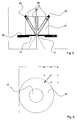
- the mobile receiver for example, a one Spacecraft or, as in the case of the one described here Embodiment on a reconnaissance vehicle 17 is located in any Distance from the transmitter, but in the direct Field of view.
- This receiver has, as from the Figures 3 and 4 can be seen, a rotary and adjustable attachment 18, the reception of the laser beam serves.
- the beam receiver 18 is made of a Solar cell surface 19 and a surrounding, the Laser beam to the transmitter back reflecting surface 20 built up.
- the solar cells convert that impinging light of the laser beam into current, the used to power the receiver. Due to the beam profile always a part of the meets Laser beam on the surrounding reflector ring 20, see that of this does not affect the solar cells 19 returning part of the light back to the transmitting unit is reflected.
- the size of the laser beam is like that chosen to be smaller than the diameter of the Solar cell 19 is to ensure that the Main part of the available light energy used for conversion into electrical energy and only a very small proportion is reflected.
- a Aligning unit that ensures that the Beam receiver with its two transverse axes always is normal to the incident beam.
- the heart of this Alignment unit is one behind a small hole 21 in the Center of the solar cells 19 arranged direction sensitive sensor 22, which is shown in detail in FIG. 5 and the off at the ends of jet pipes There are 23 arranged photodiodes 24.
- This Sensor 22 can be measured at any time, whether the Essay 18 still with its two axes perpendicular to Beam is located.
- a deviation is detected is integrated by one in this Control electronics via motors 26 and Drive elements 27 of the attachment 18 in his Orientation readjusted.
- the portion of the reflected back from the receiver Light is in the transmitter unit via a Parabolic mirror 28 collected and over about one central sensor 29 and specific filters in one Information signal regarding the position of the beam converted to the solar surface of the receiver.
- This Signal is in a control unit 30 of the transmitter used to the optimal alignment of the mirror 4 and 5 to adjust and adjust.
- the control computer 30 controls on the basis of collected reflection signal in a cascaded Control both the motors 2 and 3 for the Coarse movement and the piezoelectric crystals 9,10 and 11,12 for the fine motor movements of both mirrors 4 and 5 about their respective pivot point A and governs this way the overall system after.
- a control program that covers the entire procedural Expiration of the automatic energy transfer from one Sending unit to a mobile receiving unit includes, to the device.
- This control program consists essentially of two parts: one Search algorithm that searches and locates the Allows receiver unit in a large area, and a tracking that ensures that a found receiver unit even over long periods precisely tracked and thus constant with energy can be supplied.
- the motor-gear units of the transmitting unit are used to scan the target area over a large area line by line with a weakened laser beam after a return reflex. If such a reflection is detected, the nearer surroundings of the last reflection position are scanned more accurately in a sub-mode and the center circle R m of the reflector ring 20 is independently determined.
- the beam is positioned via the fine control by means of the piezocrystals 9, 10 and 11, 12. This is done in a two-step approach, characterized in that in a first step, a search grid in the form of a 3 by 3 matrix is measured and determines the brightest position and is selected as a new starting point, as shown in Fig. 6. This process is repeated several times.
- a subsequent second step the shape of the ring and thus the central position of the solar surfaces 19 is then detected.
- This algorithm will be illustrated with reference to FIG. From the starting point, several search steps, shown here by way of example at 3 steps, are carried out in a similar direction, in which the reflection signal strength is measured for each individual step. The step direction with the strongest signal value is adopted as the new main analysis direction, and the process is repeated until the contour of the ring reflector is completely detected. On the basis of the individual positions, the center of this surface can now be determined with a center of gravity calculation of the spanned surface, and the transmission beam can thus be guided precisely onto the solar cells 19 in the middle of the ring 20.
- This method is so oriented that, for searching and detecting the solar cells, the receiving unit does not necessarily have to be aligned already normal to the beam direction, but skews are also reliably detected and measured.
- a deterioration is on the Jumped back start position; in an improvement will the new position as a new starting position maintained.
- the procedure will start with a new one Continue step in any direction.
- the Decision whether a change of position to a Improvement or deterioration may have for example, the overall intensity of the backward reflected light, the closer the Position of the laser beam at the center of the solar cell 21 is, the less light hits the reflector ring 20 and is reflected or she may, for example by the "modulation method" i. through the Detection of the double frequency can be determined, so as described below as a separate method is.
- the designated procedure becomes the current position set the laser beam as the center.
- the beam is positioned in each vector direction and the Signal strength determined at each endpoint.
- a new vector that is strongest in the direction Intensity shows and its amount a measure of the Distance of offset is. On the basis of this vector will the new center determines.
- the procedure can be still optimize by after every single measurement already a correction step from new and old Vectors is determined. Increased by this optimization
- the responsiveness of the system to others make directional changes smoother because it is already slightly corrected after each measurement and not only after a full cycle.
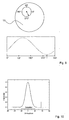
- the so-called “circle process” is in the beam direction in the second mirror 5 in horizontal direction a modulation of the frequency f and a modulation thereof in the vertical direction Frequency but out of phase by 90 degrees.
- the mirror 5 performs circular movements and the laser beam becomes the center in this way modulated.
- the reflection signal then describes over the direction a sinusoidal contour, as in FIG. 9 illustrated. The bigger the amplitude, the better Further, the beam is away from the center on the reflection foil.
- the individual phases Assign directions and it will be in the direction weakest intensity regulates to the center of To be solar surfaces.
- FIG. 11 shows the reflected light intensity as a function of the position of the laser beam on the receiver. If x M is exactly the one in the center of the photocell 19 and x 0 smaller than the radius of the photocell, then portions of the laser beam hit the reflector ring 20 both right and left in one oscillation pass.
- the back-reflected light is modulated at twice the frequency 2 f.
- a lock-in amplifier or a Fourier analysis can be used for a control loop.
- the modulation method is not limited to one dimension.
- the mirror 5 can be modulated, for example, in the horizontal as well as in the vertical direction with two different frequencies f 1 and f 2 .
- both frequencies are chosen clearly different and in a non-rational relationship to one another in order to be able to accurately recognize in the frequency analysis of the reflected-back light in which way the position of the laser beam deviates from the center of the solar cell.
Landscapes
- Engineering & Computer Science (AREA)
- Physics & Mathematics (AREA)
- Electromagnetism (AREA)
- Computer Networks & Wireless Communication (AREA)
- Power Engineering (AREA)
- Signal Processing (AREA)
- Optics & Photonics (AREA)
- Remote Sensing (AREA)
- General Physics & Mathematics (AREA)
- Astronomy & Astrophysics (AREA)
- Aviation & Aerospace Engineering (AREA)
- Plasma & Fusion (AREA)
- Optical Communication System (AREA)
- Optical Radar Systems And Details Thereof (AREA)
- Mechanical Light Control Or Optical Switches (AREA)
- Analysing Materials By The Use Of Radiation (AREA)
- Radiation-Therapy Devices (AREA)
Applications Claiming Priority (2)
| Application Number | Priority Date | Filing Date | Title |
|---|---|---|---|
| DE102004008681 | 2004-02-21 | ||
| DE102004008681A DE102004008681A1 (de) | 2004-02-21 | 2004-02-21 | Verfahren zur Energieübertragung mittels kohärenter elektromagnetischer Strahlung |
Publications (2)
| Publication Number | Publication Date |
|---|---|
| EP1566902A1 true EP1566902A1 (fr) | 2005-08-24 |
| EP1566902B1 EP1566902B1 (fr) | 2006-12-27 |
Family
ID=34706889
Family Applications (1)
| Application Number | Title | Priority Date | Filing Date |
|---|---|---|---|
| EP05000093A Expired - Lifetime EP1566902B1 (fr) | 2004-02-21 | 2005-01-05 | Procédé de transmission d'énergie utilisant des rayons électromagnétiques cohérents |
Country Status (5)
| Country | Link |
|---|---|
| US (1) | US7423767B2 (fr) |
| EP (1) | EP1566902B1 (fr) |
| JP (1) | JP4538339B2 (fr) |
| AT (1) | ATE349819T1 (fr) |
| DE (2) | DE102004008681A1 (fr) |
Cited By (4)
| Publication number | Priority date | Publication date | Assignee | Title |
|---|---|---|---|---|
| WO2007038023A1 (fr) * | 2005-09-28 | 2007-04-05 | Motorola Inc. | Chargeur par plages lumineuses pour dispositifs électroniques |
| WO2014086330A3 (fr) * | 2012-12-05 | 2014-11-27 | Eads Deutschland Gmbh | Téléalimentation sans fil en énergie pour des engins volants sans pilote |
| EP4084285A4 (fr) * | 2020-02-27 | 2023-04-05 | Minebea Mitsumi Inc. | Système d'alimentation électrique, dispositif d'alimentation électrique et procédé d'alimentation électrique |
| EP4228122A4 (fr) * | 2020-11-02 | 2024-04-10 | Huawei Technologies Co., Ltd. | Appareil d'émission laser, procédé d'émission laser et système de charge sans fil laser |
Families Citing this family (43)
| Publication number | Priority date | Publication date | Assignee | Title |
|---|---|---|---|---|
| US8182473B2 (en) | 1999-01-08 | 2012-05-22 | Palomar Medical Technologies | Cooling system for a photocosmetic device |
| US6517532B1 (en) | 1997-05-15 | 2003-02-11 | Palomar Medical Technologies, Inc. | Light energy delivery head |
| EP0991372B1 (fr) * | 1997-05-15 | 2004-08-04 | Palomar Medical Technologies, Inc. | Appareil de traitement dermatologique |
| KR20050026404A (ko) | 2002-06-19 | 2005-03-15 | 팔로마 메디칼 테크놀로지스, 인코포레이티드 | 깊이로 조직을 광열 치료하기 위한 방법 및 장치 |
| US20070019693A1 (en) * | 2005-03-07 | 2007-01-25 | Graham David S | Wireless power beaming to common electronic devices |
| US7856985B2 (en) | 2005-04-22 | 2010-12-28 | Cynosure, Inc. | Method of treatment body tissue using a non-uniform laser beam |
| WO2007035444A2 (fr) | 2005-09-15 | 2007-03-29 | Palomar Medical Technologies, Inc. | Dispositif de caractérisation optique de la peau |
| FR2899692B1 (fr) | 2006-04-06 | 2008-10-17 | Hitpool Systems Entpr Uniperso | Systeme de localisation et positionnement pour le guidage d'une entite mobile par rapport a un ou plusieurs autres objets |
| US7586957B2 (en) | 2006-08-02 | 2009-09-08 | Cynosure, Inc | Picosecond laser apparatus and methods for its operation and use |
| US20080084596A1 (en) * | 2006-10-06 | 2008-04-10 | Powerbeam, Inc. | Active Mirror for Power Beaming |
| JP2010510766A (ja) * | 2006-11-21 | 2010-04-02 | パワービーム インコーポレイテッド | 電気的にパワー供給される装置への光学的パワービーミング |
| US7711441B2 (en) * | 2007-05-03 | 2010-05-04 | The Boeing Company | Aiming feedback control for multiple energy beams |
| US8525097B2 (en) * | 2008-01-03 | 2013-09-03 | Wi-Charge Ltd. | Wireless laser system for power transmission utilizing a gain medium between retroreflectors |
| US9919168B2 (en) | 2009-07-23 | 2018-03-20 | Palomar Medical Technologies, Inc. | Method for improvement of cellulite appearance |
| IL200904A (en) * | 2009-09-13 | 2015-07-30 | Yefim Kereth | A device for detecting and locating objects |
| US20120299540A1 (en) | 2011-05-27 | 2012-11-29 | uBeam Inc. | Sender communications for wireless power transfer |
| US9819399B2 (en) | 2011-05-27 | 2017-11-14 | uBeam Inc. | Beam interaction control for wireless power transfer |
| US10148131B2 (en) * | 2011-05-27 | 2018-12-04 | uBeam Inc. | Power density control for wireless power transfer |
| US9831920B2 (en) | 2011-05-27 | 2017-11-28 | uBeam Inc. | Motion prediction for wireless power transfer |
| US9800091B2 (en) * | 2011-06-09 | 2017-10-24 | Lasermotive, Inc. | Aerial platform powered via an optical transmission element |
| KR102342629B1 (ko) | 2012-04-18 | 2021-12-22 | 싸이노슈어, 엘엘씨 | 피코초 레이저 장치 및 그를 사용한 표적 조직의 치료 방법 |
| JP5929563B2 (ja) * | 2012-07-03 | 2016-06-08 | 三菱電機株式会社 | 無線給電システム、送電装置及び受電装置 |
| WO2014145707A2 (fr) | 2013-03-15 | 2014-09-18 | Cynosure, Inc. | Systèmes de rayonnement optique picoseconde et procédés d'utilisation |
| WO2015200436A1 (fr) * | 2014-06-24 | 2015-12-30 | Board Of Trustees Of The University Of Alabama | Systèmes et procédés de transmission d'énergie sans fil |
| US10734943B2 (en) * | 2014-09-12 | 2020-08-04 | The Government Of The United States Of America, As Represented By The Secretary Of The Navy | Photovoltaics optimized for laser remote power applications at eye-safer wavelengths |
| JPWO2017056469A1 (ja) * | 2015-09-29 | 2018-07-12 | パナソニックIpマネジメント株式会社 | 光源装置および投光装置 |
| US10587152B2 (en) * | 2016-05-24 | 2020-03-10 | California Institute Of Technology | Laser wireless power transfer system with active and passive safety measures |
| CN106451666B (zh) * | 2016-11-21 | 2019-05-14 | 宇龙计算机通信科技(深圳)有限公司 | 毫米电波无线充电的装置及方法 |
| TW201823673A (zh) * | 2016-12-28 | 2018-07-01 | 鴻海精密工業股份有限公司 | 鐳射測距裝置 |
| CN111699639A (zh) | 2017-10-23 | 2020-09-22 | A·费利切利 | 能量传输设备、能量收集设备和功率定向传送系统 |
| WO2019165295A1 (fr) | 2018-02-23 | 2019-08-29 | Phion Technologies Llc | Ensemble pour conversion de puissance optique en énergie électrique |
| CN112042066A (zh) | 2018-02-26 | 2020-12-04 | 赛诺秀股份有限公司 | 调q倾腔亚纳秒激光器 |
| EP3847736A4 (fr) * | 2018-12-12 | 2022-04-06 | Hewlett-Packard Development Company, L.P. | Récepteurs et émetteurs pour la charge sans fil de dispositifs en mouvement |
| US12266947B2 (en) | 2019-04-19 | 2025-04-01 | GuRu Wireless, Inc. | Adaptive roaming and articulating generating unit for wireless power transfer |
| GB201914045D0 (en) | 2019-09-30 | 2019-11-13 | Sintef Tto As | Wireless charging of devices |
| KR102933141B1 (ko) * | 2019-10-04 | 2026-03-03 | 위-차지 리미티드. | 광학 무선 전력 시스템용 양방향 보안 인터페이스 |
| CN111123250B (zh) * | 2019-12-30 | 2021-09-28 | 成都汇蓉国科微系统技术有限公司 | 基于模式搜索算法的脉冲多普勒雷达和波束形成方法 |
| US12092581B2 (en) * | 2020-12-17 | 2024-09-17 | The Boeing Company | Laser bond inspection system and method |
| FR3122861A1 (fr) * | 2021-05-12 | 2022-11-18 | Centre National d'Études Spatiales | Engin spatial de distribution électrique, et procédé associé |
| IL286842A (en) | 2021-09-30 | 2023-04-01 | Wi Charge Ltd | A system for locating and charging wireless power receivers |
| IL287976A (en) * | 2021-11-09 | 2023-06-01 | Wi Charge Ltd | Scanning mirror for laser power transmission system |
| IT202200018984A1 (it) * | 2022-09-16 | 2024-03-16 | Torino Politecnico | Metodo e sistema di trasmissione wireless di energia nello spazio |
| US11831401B1 (en) * | 2023-03-24 | 2023-11-28 | Wireless Photonics Llc | Communication system and method for ultra-flexible and ultra-reliable laser beam based wireless communication |
Citations (6)
| Publication number | Priority date | Publication date | Assignee | Title |
|---|---|---|---|---|
| US3942894A (en) * | 1974-11-20 | 1976-03-09 | The United States Of America As Represented By The Secretary Of The Air Force | Self referencing retransmitting alignment sensor for a collimated light beam |
| US5142400A (en) * | 1989-12-26 | 1992-08-25 | Cubic Corporation | Method and apparatus for automatic acquisition and alignment of an optical beam communication link |
| US5260639A (en) * | 1992-01-06 | 1993-11-09 | The United States Of America As Represented By The Administrator Of The National Aeronautics And Space Administration | Method for remotely powering a device such as a lunar rover |
| EP1191715A2 (fr) * | 2000-09-20 | 2002-03-27 | Texas Instruments Inc. | Reseau optique sans fil avec alignement direct du faisceau optique |
| US6407535B1 (en) * | 2000-09-08 | 2002-06-18 | The Regents Of The University Of California | System for beaming power from earth to a high altitude platform |
| US6534705B2 (en) * | 2000-10-23 | 2003-03-18 | Power Beaming Corporation | Methods and apparatus for beaming power |
Family Cites Families (13)
| Publication number | Priority date | Publication date | Assignee | Title |
|---|---|---|---|---|
| AT301331B (de) * | 1968-11-25 | 1972-08-25 | Eumig | Einrichtung zur Entfernungsmessung |
| GB1269892A (en) * | 1969-03-20 | 1972-04-06 | Messerschmitt Boelkow Blohm | Weapon system for the detection of and use against stationary or moving objects |
| US4836672A (en) * | 1980-05-02 | 1989-06-06 | Riverside Research Institute | Covert optical system for probing and inhibiting remote targets |
| DE3342403C2 (de) * | 1983-11-24 | 1987-05-07 | Fraunhofer-Gesellschaft zur Förderung der angewandten Forschung e.V., 8000 München | Anordnung zum Erfassen der Lage und/oder der Abmessungen und/oder der Dreh- oder Winkellage von um eine Achse drehbaren Gegenständen bzw. deren Teilen oder Kanten von Zeigerinstrumenten |
| US4836673A (en) * | 1986-12-24 | 1989-06-06 | The Dow Chemical Company | Wavelength accuracy test solution and method |
| FR2677516B1 (fr) * | 1991-06-04 | 1994-12-09 | Europ Agence Spatiale | Terminal de communications optiques. |
| US5200606A (en) * | 1991-07-02 | 1993-04-06 | Ltv Missiles And Electronics Group | Laser radar scanning system |
| US5627669A (en) * | 1991-11-13 | 1997-05-06 | Canon Kabushiki Kaisha | Optical transmitter-receiver |
| JPH05133716A (ja) * | 1991-11-13 | 1993-05-28 | Canon Inc | 双方向空間光通信装置 |
| US5199304A (en) * | 1992-02-20 | 1993-04-06 | Duffers Scientific, Inc. | Apparatus for optically measuring specimen deformation during material testing |
| JPH07129217A (ja) * | 1993-10-29 | 1995-05-19 | Fanuc Ltd | レーザセンサを用いたロボット制御方法 |
| US6249591B1 (en) * | 1997-08-25 | 2001-06-19 | Hewlett-Packard Company | Method and apparatus for control of robotic grip or for activating contrast-based navigation |
| DE19746430A1 (de) * | 1997-10-21 | 1999-04-22 | Ferdinand Christ | Anordnung zur Nutzung von Energie aus dem oder über das Weltall, insbesondere Sonnenenergie |
-
2004
- 2004-02-21 DE DE102004008681A patent/DE102004008681A1/de not_active Withdrawn
-
2005
- 2005-01-05 DE DE502005000251T patent/DE502005000251D1/de not_active Expired - Lifetime
- 2005-01-05 AT AT05000093T patent/ATE349819T1/de not_active IP Right Cessation
- 2005-01-05 EP EP05000093A patent/EP1566902B1/fr not_active Expired - Lifetime
- 2005-01-20 US US11/040,827 patent/US7423767B2/en not_active Expired - Fee Related
- 2005-02-21 JP JP2005043884A patent/JP4538339B2/ja not_active Expired - Fee Related
Patent Citations (6)
| Publication number | Priority date | Publication date | Assignee | Title |
|---|---|---|---|---|
| US3942894A (en) * | 1974-11-20 | 1976-03-09 | The United States Of America As Represented By The Secretary Of The Air Force | Self referencing retransmitting alignment sensor for a collimated light beam |
| US5142400A (en) * | 1989-12-26 | 1992-08-25 | Cubic Corporation | Method and apparatus for automatic acquisition and alignment of an optical beam communication link |
| US5260639A (en) * | 1992-01-06 | 1993-11-09 | The United States Of America As Represented By The Administrator Of The National Aeronautics And Space Administration | Method for remotely powering a device such as a lunar rover |
| US6407535B1 (en) * | 2000-09-08 | 2002-06-18 | The Regents Of The University Of California | System for beaming power from earth to a high altitude platform |
| EP1191715A2 (fr) * | 2000-09-20 | 2002-03-27 | Texas Instruments Inc. | Reseau optique sans fil avec alignement direct du faisceau optique |
| US6534705B2 (en) * | 2000-10-23 | 2003-03-18 | Power Beaming Corporation | Methods and apparatus for beaming power |
Cited By (5)
| Publication number | Priority date | Publication date | Assignee | Title |
|---|---|---|---|---|
| WO2007038023A1 (fr) * | 2005-09-28 | 2007-04-05 | Motorola Inc. | Chargeur par plages lumineuses pour dispositifs électroniques |
| WO2014086330A3 (fr) * | 2012-12-05 | 2014-11-27 | Eads Deutschland Gmbh | Téléalimentation sans fil en énergie pour des engins volants sans pilote |
| US9837859B2 (en) | 2012-12-05 | 2017-12-05 | Airbus Defence and Space GmbH | Wireless remote energy supply for unmanned aerial vehicles |
| EP4084285A4 (fr) * | 2020-02-27 | 2023-04-05 | Minebea Mitsumi Inc. | Système d'alimentation électrique, dispositif d'alimentation électrique et procédé d'alimentation électrique |
| EP4228122A4 (fr) * | 2020-11-02 | 2024-04-10 | Huawei Technologies Co., Ltd. | Appareil d'émission laser, procédé d'émission laser et système de charge sans fil laser |
Also Published As
| Publication number | Publication date |
|---|---|
| US7423767B2 (en) | 2008-09-09 |
| EP1566902B1 (fr) | 2006-12-27 |
| ATE349819T1 (de) | 2007-01-15 |
| JP4538339B2 (ja) | 2010-09-08 |
| JP2005237012A (ja) | 2005-09-02 |
| DE102004008681A1 (de) | 2005-09-08 |
| US20050190427A1 (en) | 2005-09-01 |
| DE502005000251D1 (de) | 2007-02-08 |
Similar Documents
| Publication | Publication Date | Title |
|---|---|---|
| EP1566902B1 (fr) | Procédé de transmission d'énergie utilisant des rayons électromagnétiques cohérents | |
| DE112017000127B4 (de) | 2D Lidar-Scannen mit hoher Präzision mit einem drehbaren konkaven Spiegel und einer Strahllenkvorrichtung | |
| EP2145154B1 (fr) | Procédé de commande destiné à la production de marquages au sol et générateur de rayon de référence | |
| DE102008013066B3 (de) | Vorrichtung zur zweidimensionalen Abbildung von Szenen durch Mikrowellen-Abtastung und Verwendung der Vorrichtung | |
| DE102012102244B4 (de) | Laserradar für dreidimensionales Scannen | |
| EP1569158B1 (fr) | Méthode et appareil de balayage optique d'un objet | |
| DE102017205685B4 (de) | LIDAR-Vorrichtung mit einem dynamischen Filter und Verfahren | |
| EP2983030B1 (fr) | Scanner multiniveaux et procede destine a la saisie d'objets | |
| EP3350615A1 (fr) | Capteur lidar | |
| EP0578129A2 (fr) | Capteur formateur d'images | |
| CH623147A5 (fr) | ||
| EP3199913A1 (fr) | Dispositif de recherche automatique d'un objet cible geodesique mobile | |
| EP1914564A1 (fr) | Dispositif de détection optique | |
| DE102017223673A1 (de) | LIDAR-System zur Erfassung eines Objekts | |
| DE2224217A1 (de) | Vorrichtung zum optischen Abtasten eines Bildfeldes | |
| DE2064242A1 (de) | Abtastkamera | |
| EP3622316A1 (fr) | Système lidar et procédé permettant une détection simplifiée | |
| DE102010061726A1 (de) | Rotationslasergerät und Verfahren zur Steuerung eines Laserstrahls | |
| EP2361391B1 (fr) | Dispositif et procédé d'imagerie d'un objet par rayonnement électromagnétique haute fréquence | |
| EP3775978A1 (fr) | Dispositif lidar macroscopique | |
| DE2305679A1 (de) | Antenne zur erzeugung von abtastenden radiorichtstrahlen | |
| EP3260829A1 (fr) | Dispositif de mesure d'une aberration, système d'imagerie et procédé de mesure d'une aberration | |
| EP3914926A1 (fr) | Système optique, en particulier système lidar, ainsi que véhicule | |
| DE102004054513A1 (de) | Verfahren und Vorrichtung zum Ausrichten eines Senders | |
| DE19713336C1 (de) | Ortsempfindlicher fotoelektrischer Sensor |
Legal Events
| Date | Code | Title | Description |
|---|---|---|---|
| PUAI | Public reference made under article 153(3) epc to a published international application that has entered the european phase |
Free format text: ORIGINAL CODE: 0009012 |
|
| AK | Designated contracting states |
Kind code of ref document: A1 Designated state(s): AT BE BG CH CY CZ DE DK EE ES FI FR GB GR HU IE IS IT LI LT LU MC NL PL PT RO SE SI SK TR |
|
| AX | Request for extension of the european patent |
Extension state: AL BA HR LV MK YU |
|
| 17P | Request for examination filed |
Effective date: 20050826 |
|
| AKX | Designation fees paid |
Designated state(s): AT BE BG CH CY CZ DE DK EE ES FI FR GB GR HU IE IS IT LI LT LU MC NL PL PT RO SE SI SK TR |
|
| GRAP | Despatch of communication of intention to grant a patent |
Free format text: ORIGINAL CODE: EPIDOSNIGR1 |
|
| GRAS | Grant fee paid |
Free format text: ORIGINAL CODE: EPIDOSNIGR3 |
|
| GRAA | (expected) grant |
Free format text: ORIGINAL CODE: 0009210 |
|
| AK | Designated contracting states |
Kind code of ref document: B1 Designated state(s): AT BE BG CH CY CZ DE DK EE ES FI FR GB GR HU IE IS IT LI LT LU MC NL PL PT RO SE SI SK TR |
|
| PG25 | Lapsed in a contracting state [announced via postgrant information from national office to epo] |
Ref country code: PL Free format text: LAPSE BECAUSE OF FAILURE TO SUBMIT A TRANSLATION OF THE DESCRIPTION OR TO PAY THE FEE WITHIN THE PRESCRIBED TIME-LIMIT Effective date: 20061227 Ref country code: RO Free format text: LAPSE BECAUSE OF FAILURE TO SUBMIT A TRANSLATION OF THE DESCRIPTION OR TO PAY THE FEE WITHIN THE PRESCRIBED TIME-LIMIT Effective date: 20061227 Ref country code: LT Free format text: LAPSE BECAUSE OF FAILURE TO SUBMIT A TRANSLATION OF THE DESCRIPTION OR TO PAY THE FEE WITHIN THE PRESCRIBED TIME-LIMIT Effective date: 20061227 Ref country code: IE Free format text: LAPSE BECAUSE OF FAILURE TO SUBMIT A TRANSLATION OF THE DESCRIPTION OR TO PAY THE FEE WITHIN THE PRESCRIBED TIME-LIMIT Effective date: 20061227 Ref country code: SK Free format text: LAPSE BECAUSE OF FAILURE TO SUBMIT A TRANSLATION OF THE DESCRIPTION OR TO PAY THE FEE WITHIN THE PRESCRIBED TIME-LIMIT Effective date: 20061227 Ref country code: FI Free format text: LAPSE BECAUSE OF FAILURE TO SUBMIT A TRANSLATION OF THE DESCRIPTION OR TO PAY THE FEE WITHIN THE PRESCRIBED TIME-LIMIT Effective date: 20061227 Ref country code: DK Free format text: LAPSE BECAUSE OF FAILURE TO SUBMIT A TRANSLATION OF THE DESCRIPTION OR TO PAY THE FEE WITHIN THE PRESCRIBED TIME-LIMIT Effective date: 20061227 Ref country code: CZ Free format text: LAPSE BECAUSE OF FAILURE TO SUBMIT A TRANSLATION OF THE DESCRIPTION OR TO PAY THE FEE WITHIN THE PRESCRIBED TIME-LIMIT Effective date: 20061227 Ref country code: SI Free format text: LAPSE BECAUSE OF FAILURE TO SUBMIT A TRANSLATION OF THE DESCRIPTION OR TO PAY THE FEE WITHIN THE PRESCRIBED TIME-LIMIT Effective date: 20061227 |
|
| REG | Reference to a national code |
Ref country code: GB Ref legal event code: FG4D Free format text: NOT ENGLISH |
|
| RAP2 | Party data changed (patent owner data changed or rights of a patent transferred) |
Owner name: ASTRIUM GMBH |
|
| PG25 | Lapsed in a contracting state [announced via postgrant information from national office to epo] |
Ref country code: MC Free format text: LAPSE BECAUSE OF NON-PAYMENT OF DUE FEES Effective date: 20070131 |
|
| REG | Reference to a national code |
Ref country code: IE Ref legal event code: FG4D Free format text: LANGUAGE OF EP DOCUMENT: GERMAN |
|
| REF | Corresponds to: |
Ref document number: 502005000251 Country of ref document: DE Date of ref document: 20070208 Kind code of ref document: P |
|
| PG25 | Lapsed in a contracting state [announced via postgrant information from national office to epo] |
Ref country code: BG Free format text: LAPSE BECAUSE OF FAILURE TO SUBMIT A TRANSLATION OF THE DESCRIPTION OR TO PAY THE FEE WITHIN THE PRESCRIBED TIME-LIMIT Effective date: 20070327 Ref country code: SE Free format text: LAPSE BECAUSE OF FAILURE TO SUBMIT A TRANSLATION OF THE DESCRIPTION OR TO PAY THE FEE WITHIN THE PRESCRIBED TIME-LIMIT Effective date: 20070327 |
|
| NLT2 | Nl: modifications (of names), taken from the european patent patent bulletin |
Owner name: ASTRIUM GMBH Effective date: 20070124 |
|
| PG25 | Lapsed in a contracting state [announced via postgrant information from national office to epo] |
Ref country code: ES Free format text: LAPSE BECAUSE OF FAILURE TO SUBMIT A TRANSLATION OF THE DESCRIPTION OR TO PAY THE FEE WITHIN THE PRESCRIBED TIME-LIMIT Effective date: 20070407 |
|
| GBT | Gb: translation of ep patent filed (gb section 77(6)(a)/1977) |
Effective date: 20070320 |
|
| PG25 | Lapsed in a contracting state [announced via postgrant information from national office to epo] |
Ref country code: IS Free format text: LAPSE BECAUSE OF FAILURE TO SUBMIT A TRANSLATION OF THE DESCRIPTION OR TO PAY THE FEE WITHIN THE PRESCRIBED TIME-LIMIT Effective date: 20070427 |
|
| PG25 | Lapsed in a contracting state [announced via postgrant information from national office to epo] |
Ref country code: PT Free format text: LAPSE BECAUSE OF FAILURE TO SUBMIT A TRANSLATION OF THE DESCRIPTION OR TO PAY THE FEE WITHIN THE PRESCRIBED TIME-LIMIT Effective date: 20070528 |
|
| ET | Fr: translation filed | ||
| PLBE | No opposition filed within time limit |
Free format text: ORIGINAL CODE: 0009261 |
|
| STAA | Information on the status of an ep patent application or granted ep patent |
Free format text: STATUS: NO OPPOSITION FILED WITHIN TIME LIMIT |
|
| 26N | No opposition filed |
Effective date: 20070928 |
|
| BERE | Be: lapsed |
Owner name: EADS SPACE TRANSPORTATION G.M.B.H. Effective date: 20070131 |
|
| PG25 | Lapsed in a contracting state [announced via postgrant information from national office to epo] |
Ref country code: BE Free format text: LAPSE BECAUSE OF NON-PAYMENT OF DUE FEES Effective date: 20070131 |
|
| PG25 | Lapsed in a contracting state [announced via postgrant information from national office to epo] |
Ref country code: GR Free format text: LAPSE BECAUSE OF FAILURE TO SUBMIT A TRANSLATION OF THE DESCRIPTION OR TO PAY THE FEE WITHIN THE PRESCRIBED TIME-LIMIT Effective date: 20070328 |
|
| PG25 | Lapsed in a contracting state [announced via postgrant information from national office to epo] |
Ref country code: AT Free format text: LAPSE BECAUSE OF NON-PAYMENT OF DUE FEES Effective date: 20070105 |
|
| PG25 | Lapsed in a contracting state [announced via postgrant information from national office to epo] |
Ref country code: EE Free format text: LAPSE BECAUSE OF FAILURE TO SUBMIT A TRANSLATION OF THE DESCRIPTION OR TO PAY THE FEE WITHIN THE PRESCRIBED TIME-LIMIT Effective date: 20061227 |
|
| PG25 | Lapsed in a contracting state [announced via postgrant information from national office to epo] |
Ref country code: LU Free format text: LAPSE BECAUSE OF NON-PAYMENT OF DUE FEES Effective date: 20070105 Ref country code: CY Free format text: LAPSE BECAUSE OF FAILURE TO SUBMIT A TRANSLATION OF THE DESCRIPTION OR TO PAY THE FEE WITHIN THE PRESCRIBED TIME-LIMIT Effective date: 20061227 |
|
| REG | Reference to a national code |
Ref country code: CH Ref legal event code: PL |
|
| PG25 | Lapsed in a contracting state [announced via postgrant information from national office to epo] |
Ref country code: HU Free format text: LAPSE BECAUSE OF FAILURE TO SUBMIT A TRANSLATION OF THE DESCRIPTION OR TO PAY THE FEE WITHIN THE PRESCRIBED TIME-LIMIT Effective date: 20070628 Ref country code: TR Free format text: LAPSE BECAUSE OF FAILURE TO SUBMIT A TRANSLATION OF THE DESCRIPTION OR TO PAY THE FEE WITHIN THE PRESCRIBED TIME-LIMIT Effective date: 20061227 |
|
| PG25 | Lapsed in a contracting state [announced via postgrant information from national office to epo] |
Ref country code: LI Free format text: LAPSE BECAUSE OF NON-PAYMENT OF DUE FEES Effective date: 20090131 Ref country code: CH Free format text: LAPSE BECAUSE OF NON-PAYMENT OF DUE FEES Effective date: 20090131 |
|
| REG | Reference to a national code |
Ref country code: DE Ref legal event code: R082 Ref document number: 502005000251 Country of ref document: DE Representative=s name: ELBPATENT - MARSCHALL & PARTNER PARTGMBB, DE |
|
| REG | Reference to a national code |
Ref country code: FR Ref legal event code: PLFP Year of fee payment: 12 |
|
| REG | Reference to a national code |
Ref country code: FR Ref legal event code: PLFP Year of fee payment: 13 |
|
| PGFP | Annual fee paid to national office [announced via postgrant information from national office to epo] |
Ref country code: NL Payment date: 20170124 Year of fee payment: 13 |
|
| PGFP | Annual fee paid to national office [announced via postgrant information from national office to epo] |
Ref country code: FR Payment date: 20170124 Year of fee payment: 13 Ref country code: DE Payment date: 20161129 Year of fee payment: 13 |
|
| PGFP | Annual fee paid to national office [announced via postgrant information from national office to epo] |
Ref country code: GB Payment date: 20170125 Year of fee payment: 13 |
|
| PGFP | Annual fee paid to national office [announced via postgrant information from national office to epo] |
Ref country code: IT Payment date: 20170125 Year of fee payment: 13 |
|
| REG | Reference to a national code |
Ref country code: DE Ref legal event code: R082 Ref document number: 502005000251 Country of ref document: DE Representative=s name: ELBPATENT - MARSCHALL & PARTNER PARTGMBB, DE Ref country code: DE Ref legal event code: R081 Ref document number: 502005000251 Country of ref document: DE Owner name: AIRBUS DEFENCE AND SPACE GMBH, DE Free format text: FORMER OWNER: EADS SPACE TRANSPORTATION GMBH, 28199 BREMEN, DE |
|
| REG | Reference to a national code |
Ref country code: NL Ref legal event code: HC Owner name: AIRBUS DS GMBH; DE Free format text: DETAILS ASSIGNMENT: CHANGE OF OWNER(S), CHANGE OF OWNER(S) NAME; FORMER OWNER NAME: ASTRIUM GMBH Effective date: 20180220 Ref country code: NL Ref legal event code: PD Owner name: AIRBUS DEFENCE AND SPACE GMBH; DE Free format text: DETAILS ASSIGNMENT: CHANGE OF OWNER(S), MERGE; FORMER OWNER NAME: EADS SPACE TRANSPORTATION GMBH Effective date: 20180220 |
|
| REG | Reference to a national code |
Ref country code: GB Ref legal event code: 732E Free format text: REGISTERED BETWEEN 20180405 AND 20180411 |
|
| REG | Reference to a national code |
Ref country code: DE Ref legal event code: R119 Ref document number: 502005000251 Country of ref document: DE |
|
| REG | Reference to a national code |
Ref country code: FR Ref legal event code: TP Owner name: AIRBUS DS GMBH, DE Effective date: 20180717 |
|
| REG | Reference to a national code |
Ref country code: FR Ref legal event code: CD Owner name: AIRBUS DS GMBH, DE Effective date: 20180718 |
|
| REG | Reference to a national code |
Ref country code: NL Ref legal event code: MM Effective date: 20180201 |
|
| GBPC | Gb: european patent ceased through non-payment of renewal fee |
Effective date: 20180105 |
|
| PG25 | Lapsed in a contracting state [announced via postgrant information from national office to epo] |
Ref country code: FR Free format text: LAPSE BECAUSE OF NON-PAYMENT OF DUE FEES Effective date: 20180131 Ref country code: DE Free format text: LAPSE BECAUSE OF NON-PAYMENT OF DUE FEES Effective date: 20180801 |
|
| REG | Reference to a national code |
Ref country code: FR Ref legal event code: ST Effective date: 20180928 |
|
| PG25 | Lapsed in a contracting state [announced via postgrant information from national office to epo] |
Ref country code: GB Free format text: LAPSE BECAUSE OF NON-PAYMENT OF DUE FEES Effective date: 20180105 Ref country code: NL Free format text: LAPSE BECAUSE OF NON-PAYMENT OF DUE FEES Effective date: 20180201 |
|
| PG25 | Lapsed in a contracting state [announced via postgrant information from national office to epo] |
Ref country code: IT Free format text: LAPSE BECAUSE OF NON-PAYMENT OF DUE FEES Effective date: 20180105 |