EP1567215B1 - Vorrichtung zum verschrauben mediumfuehrender gewindeverbindungen, insbesondere luer-lock-verbindungen - Google Patents
Vorrichtung zum verschrauben mediumfuehrender gewindeverbindungen, insbesondere luer-lock-verbindungen Download PDFInfo
- Publication number
- EP1567215B1 EP1567215B1 EP03811708A EP03811708A EP1567215B1 EP 1567215 B1 EP1567215 B1 EP 1567215B1 EP 03811708 A EP03811708 A EP 03811708A EP 03811708 A EP03811708 A EP 03811708A EP 1567215 B1 EP1567215 B1 EP 1567215B1
- Authority
- EP
- European Patent Office
- Prior art keywords
- inside part
- outside
- essentially
- axially
- aligned
- Prior art date
- Legal status (The legal status is an assumption and is not a legal conclusion. Google has not performed a legal analysis and makes no representation as to the accuracy of the status listed.)
- Expired - Lifetime
Links
Images

Classifications
-
- A—HUMAN NECESSITIES
- A61—MEDICAL OR VETERINARY SCIENCE; HYGIENE
- A61M—DEVICES FOR INTRODUCING MEDIA INTO, OR ONTO, THE BODY; DEVICES FOR TRANSDUCING BODY MEDIA OR FOR TAKING MEDIA FROM THE BODY; DEVICES FOR PRODUCING OR ENDING SLEEP OR STUPOR
- A61M5/00—Devices for bringing media into the body in a subcutaneous, intra-vascular or intramuscular way; Accessories therefor, e.g. filling or cleaning devices, arm-rests
- A61M5/178—Syringes
- A61M5/31—Details
- A61M5/32—Needles; Details of needles pertaining to their connection with syringe or hub; Accessories for bringing the needle into, or holding the needle on, the body; Devices for protection of needles
- A61M5/3205—Apparatus for removing or disposing of used needles or syringes, e.g. containers; Means for protection against accidental injuries from used needles
- A61M5/321—Means for protection against accidental injuries by used needles
- A61M5/3213—Caps placed axially onto the needle, e.g. equipped with finger protection guards
-
- A—HUMAN NECESSITIES
- A61—MEDICAL OR VETERINARY SCIENCE; HYGIENE
- A61M—DEVICES FOR INTRODUCING MEDIA INTO, OR ONTO, THE BODY; DEVICES FOR TRANSDUCING BODY MEDIA OR FOR TAKING MEDIA FROM THE BODY; DEVICES FOR PRODUCING OR ENDING SLEEP OR STUPOR
- A61M5/00—Devices for bringing media into the body in a subcutaneous, intra-vascular or intramuscular way; Accessories therefor, e.g. filling or cleaning devices, arm-rests
- A61M5/002—Packages specially adapted therefor, e.g. for syringes or needles, kits for diabetics
- A61M5/003—Kits for diabetics
-
- B—PERFORMING OPERATIONS; TRANSPORTING
- B25—HAND TOOLS; PORTABLE POWER-DRIVEN TOOLS; MANIPULATORS
- B25B—TOOLS OR BENCH DEVICES NOT OTHERWISE PROVIDED FOR, FOR FASTENING, CONNECTING, DISENGAGING, OR HOLDING
- B25B13/00—Spanners; Wrenches
- B25B13/46—Spanners; Wrenches of the ratchet type, for providing a free return stroke of the handle
- B25B13/461—Spanners; Wrenches of the ratchet type, for providing a free return stroke of the handle with concentric driving and driven member
- B25B13/462—Spanners; Wrenches of the ratchet type, for providing a free return stroke of the handle with concentric driving and driven member the ratchet parts engaging in a direction radial to the tool operating axis
-
- B—PERFORMING OPERATIONS; TRANSPORTING
- B25—HAND TOOLS; PORTABLE POWER-DRIVEN TOOLS; MANIPULATORS
- B25B—TOOLS OR BENCH DEVICES NOT OTHERWISE PROVIDED FOR, FOR FASTENING, CONNECTING, DISENGAGING, OR HOLDING
- B25B13/00—Spanners; Wrenches
- B25B13/46—Spanners; Wrenches of the ratchet type, for providing a free return stroke of the handle
- B25B13/461—Spanners; Wrenches of the ratchet type, for providing a free return stroke of the handle with concentric driving and driven member
- B25B13/466—Spanners; Wrenches of the ratchet type, for providing a free return stroke of the handle with concentric driving and driven member the ratchet parts engaging in an axial direction
-
- B—PERFORMING OPERATIONS; TRANSPORTING
- B25—HAND TOOLS; PORTABLE POWER-DRIVEN TOOLS; MANIPULATORS
- B25B—TOOLS OR BENCH DEVICES NOT OTHERWISE PROVIDED FOR, FOR FASTENING, CONNECTING, DISENGAGING, OR HOLDING
- B25B23/00—Details of, or accessories for, spanners, wrenches, screwdrivers
- B25B23/14—Arrangement of torque limiters or torque indicators in wrenches or screwdrivers
- B25B23/141—Mechanical overload release couplings
-
- A—HUMAN NECESSITIES
- A61—MEDICAL OR VETERINARY SCIENCE; HYGIENE
- A61M—DEVICES FOR INTRODUCING MEDIA INTO, OR ONTO, THE BODY; DEVICES FOR TRANSDUCING BODY MEDIA OR FOR TAKING MEDIA FROM THE BODY; DEVICES FOR PRODUCING OR ENDING SLEEP OR STUPOR
- A61M2205/00—General characteristics of the apparatus
- A61M2205/58—Means for facilitating use, e.g. by people with impaired vision
- A61M2205/581—Means for facilitating use, e.g. by people with impaired vision by audible feedback
-
- A—HUMAN NECESSITIES
- A61—MEDICAL OR VETERINARY SCIENCE; HYGIENE
- A61M—DEVICES FOR INTRODUCING MEDIA INTO, OR ONTO, THE BODY; DEVICES FOR TRANSDUCING BODY MEDIA OR FOR TAKING MEDIA FROM THE BODY; DEVICES FOR PRODUCING OR ENDING SLEEP OR STUPOR
- A61M5/00—Devices for bringing media into the body in a subcutaneous, intra-vascular or intramuscular way; Accessories therefor, e.g. filling or cleaning devices, arm-rests
- A61M5/178—Syringes
- A61M5/31—Details
- A61M5/32—Needles; Details of needles pertaining to their connection with syringe or hub; Accessories for bringing the needle into, or holding the needle on, the body; Devices for protection of needles
- A61M5/34—Constructions for connecting the needle, e.g. to syringe nozzle or needle hub
- A61M5/347—Constructions for connecting the needle, e.g. to syringe nozzle or needle hub rotatable, e.g. bayonet or screw
Definitions
- the invention relates to a device for screwing medium-carrying threaded connections, in particular Luer-lock connections, with an outer part and an inner part rotatably received therein, which has means for receiving the one, threaded connecting part or a rotationally secured with this additional part, wherein inhibiting means are present which allow a rotation of the inner part relative to the outer part only in one direction of rotation and oppose this rotation a resistance.
- Luer-lock fasteners are used in particular in the field of medical technology to connect parts together, inside which flows a medium, in particular a liquid.
- These parts include, for example, infusion containers and associated leads or syringes and associated needles. To ensure that such connections are tight and do not come loose, they must be tightened with a certain amount of torque. On the other hand, the mostly made of plastic threaded parts must not be tightened too much, because they can break otherwise.
- the invention has for its object to provide a device for tightening fluid-carrying threaded connections, in particular Luer-lock connections, which is simple and inexpensive to manufacture, easy to use and the torque when tightening threaded connections both downwards and upwards safely limited.
- the invention solves this problem by the resistance increases when turning up to a maximum load and then drops sharply.
- the resistance is thus preferably a sawtooth, wherein the strong decrease of the torque can be tactually and / or acoustically perceived by the user of the device, whereby it signals to us that the desired torque for tightening the threaded connection is reached.
- the means for receiving consist of an existing inside bore with axially disposed therein longitudinal grooves. These longitudinal grooves accommodate the existing on a conventional needle carrier of the Luer-lock type or on an additional part longitudinal ribs and thus ensure safe transmission of the tightening torque.
- the additional part is preferably a plugged onto the connecting part needle cap.
- the inhibiting means arranged in the outer part, substantially axially aligned projections which cooperate with arranged on the inner part, substantially axially aligned recesses and there are spring means, soft the outer part and the inner part in the axial direction against each other tighten.
- These projections and depressions can advantageously cause a perceptible and visible periodic axial displacement of the inner part relative to the outer part.
- a kinematic reversal of this principle is possible, in which the recesses in the outer part and the projections are arranged on the inner part.
- Another embodiment of the invention provides that the inhibiting means arranged in the outer part, having substantially radially aligned projections which cooperate with arranged on the inner part, substantially tangentially aligned lamellae, wherein the lamellae are resiliently formed in a substantially radial direction.
- the inhibiting means arranged in the outer part, having substantially radially aligned projections which cooperate with arranged on the inner part, substantially tangentially aligned lamellae, wherein the lamellae are resiliently formed in a substantially radial direction.
- Another aspect of the invention relates to a charging station for the preparation of an injection device, which contains a device according to the invention.
- the charging stations may contain other functional elements that serve to prepare an injection device, in particular an autoinjector.
- the inventive device is preferably removed removably received in the charging station.
- a special embodiment of the charging station is at the same time as a container for the storage of Parts of an injection device formed. This allows the user of an injection device, easy to carry the necessary items with him and keep clear.
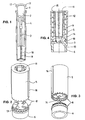
- FIG. 1 shows a known example of an injection needle 1 with a needle carrier 2 made of plastic, in which a cannula 3 is cast from metal.
- the needle carrier 2 has at its upper edge in the figure two tabs 17, which assume the function of an external thread, which can be screwed into a corresponding internal thread to the injection needle to connect with a syringe.
- ribs 4 are formed, which are received in corresponding longitudinal grooves in a needle cap 18 and thus form a rotationally fixed connection with this.
- the needle cap 18 in turn has outer ribs 19, which also serve to transmit a torque.
- the in the FIGS. 2 to 4 illustrated first embodiment of the device has an outer sleeve 5, which is connected via a snap connection 7 with a bottom 6.
- the sleeve 5 can not rotate relative to the bottom 6, both parts are provided with a toothing 8.
- a rotary member 9 is mounted, which has an axial opening, in the longitudinal grooves 11 for receiving the ribs 19 of the needle cap 18 are present.
- a compression spring spring 12 is formed between the sleeve 5 and the rotary member 9 as a compression spring spring 12, which is axially supported on an upper edge 15 of the sleeve 5 and a lower flange 10 of the rotary member 9 and the rotary member 9 urges against the bottom 6.
- this floor 6 there are arranged a number, in the present example, four projections 13, each having a vertical and a sloping flank.
- recesses 14 are incorporated, which correspond to the projections 13 in number and shape. If, for example, an injection needle 1 is introduced into the rotary part 9, the ribs 4 on the needle carrier 2 engage in the longitudinal grooves 11 of the rotary part 9, so that the needle carrier 2 can not rotate in the rotary part 9.
- the syringe is rotated clockwise, there is first a relative rotation between the syringe and the needle carrier 2, wherein the thread is tightened. If a predetermined minimum torque is reached, the rotary member 9 begins to rotate relative to the sleeve 5.
- FIGS. 5 and 6 show a second advantageous embodiment of the inventive device, which consists of only two parts, namely a sleeve 25 and disposed in the sleeve rotary member 29, both of which can be made of plastic by injection molding.
- the rotary member 29 has tangentially formed fins 33 in its lower part. These lamellae 33 act as bending springs and are guided, when the rotary part 29 is rotated, past longitudinal ribs 28 which are formed on the inside in the sleeve 25, the lamellae 33 yielding radially in a springy manner. After passing the longitudinal ribs 28, the fins 33 snap back outward, producing a clicking sound that indicates to the user that the desired torque has been achieved.
- This device is very easy to assemble by the rotary member 29 is pushed from above into the sleeve 25, wherein the fins 33 in the upper, slightly conical part of the sleeve 25 deform symmetrically inward and after passing the paragraph 27 of the sleeve 25 after grab outside. As a result, the rotary member is held up. Down the rotary member 29 is held in the sleeve 25 by an integrally formed on the rotary member 29 upper edge 30 which abuts a further shoulder 26 of the sleeve 25. Also in this embodiment, 25 longitudinal ribs 36 are provided on the outer circumference of the sleeve, which serve for better grip when the device is held by hand, or serve as anti-rotation, when the device is placed in a charging station, as described below.
- the inner part 9 or 29 can only be rotated in one direction and locked in the opposite direction.
- the device according to the invention can therefore also be used for loosening threaded connections.
- FIG. 7 shows a charging station 40 for the preparation of an auto-injector.
- Autoinjectors are used in particular for the administration of medicaments which the affected patient himself injects. They usually work with spring force, automatically inserted first a hypodermic needle and then an active ingredient is distributed. When the autoinjector is equipped for use with filled syringes, tensioning of the springs, placement of the injection needle on the syringe, and insertion of the syringe into the autoinjector are among these preparations.
- Elements which facilitate or facilitate these preparations may comprise, for example, a chuck 43 which serves to tension the springs, and a receptacle 44 may be provided for an assembly aid (not shown) with the aid of which the auto-injector is assembled after insertion of the syringe becomes.
- the charging station 40 may be equipped with receiving troughs 41 and 42, which serve for the storage of the auto-injector or parts thereof and / or the aforementioned assembly aid.
- the present charging station further includes a device 45, as described above with reference to two embodiments, which serves to tighten the threaded connection between the injection needle and the syringe. This device 45 is preferably removably received in a cylindrical recess of the charging station, which recess has longitudinal grooves into which the longitudinal ribs 16 and 36 of the device fit.
Landscapes
- Health & Medical Sciences (AREA)
- Engineering & Computer Science (AREA)
- Mechanical Engineering (AREA)
- Life Sciences & Earth Sciences (AREA)
- General Health & Medical Sciences (AREA)
- Biomedical Technology (AREA)
- Heart & Thoracic Surgery (AREA)
- Hematology (AREA)
- Vascular Medicine (AREA)
- Animal Behavior & Ethology (AREA)
- Anesthesiology (AREA)
- Public Health (AREA)
- Veterinary Medicine (AREA)
- Diabetes (AREA)
- Environmental & Geological Engineering (AREA)
- Infusion, Injection, And Reservoir Apparatuses (AREA)
- External Artificial Organs (AREA)
- Mutual Connection Of Rods And Tubes (AREA)
- Sanitary Device For Flush Toilet (AREA)
Description
- Die Erfindung betrifft eine Vorrichtung zum Verschrauben mediumführender Gewindeverbindungen, insbesondere Luer-Lock-Verbindungen, mit einem Aussenteil und einem darin drehbar aufgenommenen Innenteil, welcher über Mittel zur Aufnahme des einen, gewindetragenden Verbindungsteils oder eines mit diesem verdrehgesicherten Zusatzteils verfügt, wobei Hemmmittel vorhanden sind, welche eine Drehung des Innenteils gegenüber dem Aussenteil nur in eine Drehrichtung zulassen und dieser Drehung einen Widerstand entgegensetzen.
- Luer-Lock Befestigungen werden insbesondere im Bereich der Medizintechnik eingesetzt, um Teile miteinander zu verbinden, in deren Innerem ein Medium, insbesondere eine Flüssigkeit fliesst. Zu diesen Teilen gehören beispielsweise Infusionsbehälter und zugehörige Leitungen oder Injektionsspritzen und zugehörige Nadeln. Damit solche Verbindungen dicht sind und sich nicht lösen, müssen sie mit einem gewissen Drehmoment angezogen werden. Andererseits dürfen die meistens aus Kunststoff bestehenden Gewindeteile auch nicht zu stark angezogen werden, weil sie sonst brechen können.
- In der Druckschrift
WO 00/51667 - Der Erfindung liegt die Aufgabe zugrunde, eine Vorrichtung zum Anziehen flüssigkeitsführender Gewindeverbindungen, insbesondere Luer-Lock-Verbindungen vorzuschlagen, die einfach und kostengünstig herzustellen, einfach zu bedienen ist und das Drehmoment beim Anziehen von Gewindeverbindungen sowohl nach unten als auch nach oben sicher begrenzt.
- Die Erfindung löst diese Aufgabe, indem der Widerstand beim Drehen bis zu einer Maximallast zunimmt und anschliessend stark abfällt. Der Widerstand verläuft also vorzugsweise sägezahnförmig, wobei die starke Abnahme des Drehmoments vom Benutzer der Vorrichtung taktil und/oder akustisch wahrgenommen werden kann, wodurch ihm signalisiert wir, dass das zum Anziehen der Gewindeverbindung gewünschte Drehmoment erreicht ist.
- Nach einer bevorzugten Ausführungsart der Erfindung bestehen die Mittel zur Aufnahme aus einer im Innenteil vorhandenen Bohrung mit axial darin angeordneten Längsnuten. Diese Längsnuten nehmen die an einem üblichen Nadelträger des Luer-Lock-Typs oder an einem Zusatzteil vorhandenen Längsrippen auf und sorgen so für eine sichere Übertragung des Anzugs-Drehmoments. Der Zusatzteil ist bevorzugt eine auf den Verbindungsteil aufgesteckte Nadelschutzkappe.
- Nach einer weiteren Ausführungsart der Erfindung weisen die Hemm-Mittel im Aussenteil angeordnete, im Wesentlichen axial ausgerichtete Vorsprünge auf, die mit am Innenteil angeordneten, im Wesentlichen axial ausgerichteten Vertiefungen zusammenwirken und es sind Federmittel vorhanden, weiche den Aussenteil und den Innenteil in axialer Richtung gegeneinander spannen. Diese Vorsprünge und Vertiefungen können in vorteilhafter Weise eine fühl- und sichtbare periodische axiale Verschiebung des Innenteils gegenüber dem Aussenteil bewirken. Selbstverständlich ist auch eine kinematische Umkehr dieses Prinzips möglich, bei der die Vertiefungen im Aussenteil und die Vorsprünge am Innenteil angeordnet sind.
- Eine andere Ausführungsart der Erfindung sieht vor, dass die Hemm-Mittel im Aussenteil angeordnete, im Wesentlichen radial ausgerichtete Vorsprünge aufweisen, die mit am Innenteil angeordneten, im Wesentlichen tangential ausgerichteten Lamellen zusammenwirken, wobei die Lamellen in im Wesentlichen radialer Richtung federnd ausgebildet sind. Dies erlaubt eine besonders einfache Realisation der Vorrichtung mit nur zwei Teilen. Natürlich ist auch hier die kinematische Umkehr möglich, indem die Vorsprünge am Innenteil und die Lamellen im Aussenteil angeordnet werden.
- Ein anderer Aspekt der Erfindung betrifft eine Ladestation für die Vorbereitung einer Injektionsvorrichtung, welche eine erfindungsgemässe Vorrichtung enthält. Dabei kann die Ladestationen noch andere funktionelle Elemente enthalten, die der Vorbereitung einer Injektionsvorrichtung, insbesondere eines Autoinjektors, dienen. Die erfindungsgemässe Vorrichtung ist vorzugsweise herausnehmbar in der Ladestation aufgenommen. Eine besondere Ausführungsart der Ladestation ist gleichzeitig als Behältnis zur Aufbewahrung von Teilen einer Injektionsvorrichtung ausgebildet. Dies ermöglicht dem Benutzer einer Injektionsvorrichtung, die benötigten Einzelteile einfach mit sich zu tragen und übersichtlich aufzubewahren.
- Besondere Ausführungsarten der Erfindung werden nachfolgend unter Bezugnahme auf die beiliegenden Zeichnungen beispielsweise näher erläutert. Es zeigt:
- Figur 1
- eine perspektivische Ansicht einer Injektionsnadel mit Luer-Lock- Verbindung,
- Figur 2
- eine teilweise auseinander gezogene Ansicht von schräg oben auf eine erste Ausführungsart der erfindungsgemässen Vorrichtung,
- Figur 3
- eine teilweise auseinander gezogene Ansicht von schräg unten auf die erste Ausführungsart gemäss
Figur 2 , - Figur 4
- einen Längsschnitt durch die erste Ausführungsart gemäss den
Figu- ren 2 und 3 , - Figur 5
- eine Ansicht von schräg unten auf eine zweite Ausführungsart der erfindungsgemässen Vorrichtung,
- Figur 6
- einen Längsschnitt durch die zweite Ausführungsart gemäss
Figur 5 und - Figur 7
- eine perspektivische Ansicht einer Ladestation für eine Injektionsvor- richtung, mit einer Vorrichtung zum Anziehen einer Gewindeverbin- dung.
- Die
Figur 1 zeigt ein bekanntes Beispiel einer Injektionsnadel 1 mit einem Nadelträger 2 aus Kunststoff, in welchem eine Kanüle 3 aus Metall eingegossen ist. Der Nadelträger 2 weist an seinem in der Figur oberen Rand zwei Lappen 17 auf, welche die Funktion eines Aussengewindes übernehmen, das in ein entsprechendes Innengewinde eingeschraubt werden kann, um die injektionsnadel mit einer Spritze zu verbinden. Aussen am Nadelträger 2 sind Rippen 4 angeformt, die in entsprechenden Längsnuten in einer Nadelschutzkappe 18 aufgenommen sind und so mit dieser eine drehfeste Verbindung bilden. Die Nadelschutzkappe 18 weist ihrerseits äussere Rippen 19 auf, die ebenfalls der Übertragung eines Drehmoments dienen. Die im folgenden beschriebenen Ausführungsarten einer erfindungsgemässen Vorrichtung zum Anziehen flüssigkeitsführender Gewindeverbindungen sind speziell für Injektionsnadeln dieser Art bestimmt. - Die in den
Figuren 2 bis 4 dargestellte erste Ausführungsart der Vorrichtung weist eine äussere Hülse 5 auf, die über eine Schnapp-Verbindung 7 mit einem Boden 6 verbunden ist. Damit sich die Hülse 5 gegenüber dem Boden 6 nicht drehen kann, sind beide Teile mit einer Verzahnung 8 versehen. In der Hülse 5 ist ein Drehteil 9 gelagert, der eine axiale Öffnung aufweist, in der Längsnuten 11 zur Aufnahme der Rippen 19 der Nadelschutzkappe 18 vorhanden sind. Zwischen der Hülse 5 und dem Drehteil 9 befindet sich eine als Druckfeder ausgebildete Feder 12, die sich axial an einem oberen Rand 15 der Hülse 5 und einem unteren Flansch 10 des Drehteils 9 abstützt und den Drehteil 9 gegen den Boden 6 drängt. Auf diesem Boden 6 sind eine Anzahl, im vorliegenden Beispiel vier Vorsprünge 13 angeordnet, von denen jeder eine vertikale und eine geneigte Flanke hat. In der unteren Stirnseite des Drehteils 9 sind Vertiefungen 14 eingearbeitet, die bezüglich Anzahl und Form den Vorsprüngen 13 entsprechen. Wenn nun beispielsweise eine Injektionsnadel 1 in den Drehteil 9 eingeführt wird, greifen die Rippen 4 am Nadelträger 2 in die Längsnuten 11 des Drehteils 9, so dass sich der Nadelträger 2 nicht im Drehteil 9 drehen kann. Wird nun die Spritze im Uhrzeigersinn gedreht, erfolgt zuerst eine relative Drehung zwischen der Spritze und dem Nadelträger 2, wobei das Gewinde angezogen wird. Wird ein vorbestimmtes minimales Drehmoment erreicht, beginnt sich der Drehteil 9 gegenüber der Hülse 5 zu drehen. Dabei gleiten die Vertiefungen 14 des Drehteils über die Vorsprünge 13 des Bodens 6, wobei der Drehteil entgegen der Kraft der Feder 12 so weit angehoben wird, bis - im vorliegenden Beispiel nach einem Drehwinkel von 90° - die Vertiefungen 14 wiederum mit den Vorsprüngen 13 fluchten. In diesem Moment wird der Drehteil 9 durch die Feder 12 nach unten gestossen und schlägt auf dem Boden 6 auf, wodurch dem Benutzer sowohl über das Gefühl als auch das Gehör signalisiert wird, dass das gewünschte Drehmoment erreicht ist. Am Aussenumfang der Hülse 5 vorgesehene Längsrippen 16 dienen einerseits dem besseren Halt, wenn die Vorrichtung mit der Hand gehalten wird und andererseits als Verdrehschutz, wenn die Vorrichtung in einer Ladestation angeordnet wird, wie dies weiter unten noch beschrieben wird. - Die
Figuren 5 und 6 zeigen eine zweite, vorteilhafte Ausführungsart der erfindungsgemässen Vorrichtung, welche aus nur zwei Teilen besteht, nämlich aus einer Hülse 25 und einem in der Hülse angeordneten Drehteil 29, die beide aus Kunststoff im Spritzgiessverfahren hergestellt werden können. Der Drehteil 29 weist in seinem unteren Teil tangential angeformte Lamellen 33 auf. Diese Lamellen 33 wirken als Biegefedern und werden beim Drehen des Drehteils 29 an Längsrippen 28 vorbei geführt, die innen in der Hülse 25 angeformt sind, wobei die Lamellen 33 radial federnd nachgeben. Nach dem Passieren der Längsrippen 28 schnappen die Lamellen 33 wieder nach aussen, wobei ein klickendes Geräusch entsteht, das dem Benutzer anzeigt, dass das gewünschte Drehmoment erreicht ist. Diese Vorrichtung ist sehr einfach zu montieren, indem der Drehteil 29 von oben in die Hülse 25 geschoben wird, wobei sich die Lamellen 33 im oberen, leicht konischen Teil der Hülse 25 symmetrisch nach innen verformen und nach dem Passieren des Absatzes 27 der Hülse 25 nach aussen schnappen. Dadurch ist der Drehteil nach oben gehalten. Nach unten ist der Drehteil 29 in der Hülse 25 durch einen am Drehteil 29 angeformten oberen Rand 30 gehalten, der an einem weiteren Absatz 26 der Hülse 25 ansteht. Auch bei diesem Ausführungsbeispiel sind am Aussenumfang der Hülse 25 Längsrippen 36 vorgesehen, die dem besseren Halt dienen, wenn die Vorrichtung mit der Hand gehalten wird, oder als Verdrehschutz dienen, wenn die Vorrichtung in einer Ladestation angeordnet wird, wie dies nachstehend beschrieben wird. - Aus der vorangehenden Beschreibung der beiden Ausführungsarten der Erfindung geht hervor, dass der Innenteil 9 beziehungsweise 29 nur in einer Richtung gedreht werden kann und in der Gegenrichtung gesperrt wird. Die erfindungsgemässe Vorrichtung kann daher auch zum Lösen von Gewindeverbindungen verwendet werden.
-
Figur 7 zeigt eine Ladestation 40 für die Vorbereitung eines Autoinjektors. Autoinjektoren dienen insbesondere zur Verabreichung von Medikamenten, die sich der betroffene Patient selbst injiziert. Sie arbeiten üblicherweise mit Federkraft, wobei automatisch zuerst eine Injektionsnadel eingestochen und danach ein Wirkstoff ausgeschüttet wird. Wenn der Autoinjektor zur Verwendung von gefüllten Spritzen ausgestattet ist, gehören das Spannen der Federn, das Aufsetzen der Injektionsnadel auf die Spritze und das Einsetzen der Spritze in den Autoinjektor zu diesen Vorbereitungen. Elemente, welche diese Vorbereitungen ermöglichen oder erleichtern, können beispielsweise einen Spannzapfen 43 umfassen, der zum Spannen der Federn dient, und es kann eine Aufnahme 44 für eine (nicht dargestellte) Montagehilfe vorgesehen sein, mit deren Hilfe der Autoinjektor nach dem Einsetzen der Spritze zusammengesetzt wird. Weiter kann die Ladestation 40 mit Aufnahmemulden 41 und 42 ausgestattet sein, die zur Aufbewahrung des Autoinjektors oder Teilen davon und/oder der erwähnten Montagehilfe dienen. Die vorliegende Ladestation enthält ferner eine Vorrichtung 45, wie sie vorangehend anhand zweier Ausführungsbeispiele beschrieben wurde und die zum Anziehen der Gewindeverbindung zwischen der Injektionsnadel und der Spritze dient. Diese Vorrichtung 45 ist vorzugsweise herausnehmbar in einer zylindrischen Ausnehmung der Ladestation aufgenommen, welche Ausnehmung Längsnuten aufweist, in welche die Längsrippen 16 beziehungsweise 36 der Vorrichtung passen.
Claims (10)
- Vorrichtung zum Verschrauben einer flüssigkeitsführenden Gewindeverbindung zwischen einer Injektionsvorrichtung und einer Injektionsnadel (1), insbesondere Luer-Lock-Verbindung, mit einem Aussenteil (5; 25) und einem darin drehbar aufgenommenen Innenteil (9; 29), welcher über Mittel (11) zur Aufnahme eines gewindetragenden Verbindungsteils (2) der Injektionsnadel (1) oder eines mit dem gewindetragenden Verbindungsteil (2) der Injektionsnadel (1) verdrehgesicherten Zusatzteils (18) verfügt, dadurch gekennzeichnet, dass Hemmmittel (13, 14; 28, 33) vorhanden sind, welche eine Drehung des Innenteils (9; 29) gegenüber dem Aussenteil (5; 25) nur in eine Drehrichtung zulassen und dieser Drehung einen Widerstand entgegensetzen, der beim Drehen bis zu einer Maximallast zunimmt und anschliessend stark abfällt.
- Vorrichtung nach Anspruch 1, dadurch gekennzeichnet, dass die Mittel zur Aufnahme auf einer im Innenteil (9; 29) vorhandenen Bohrung mit axial darin angeordneten Längsnuten (11) bestehen.
- Vorrichtung nach Anspruch 1 oder 2, dadurch gekennzeichnet, dass die Hemmmittel (13, 14) im Aussenteil (5) angeordnete, im Wesentlichen axial ausgerichtete Vorsprünge (13) aufweisen, die mit am Innenteil (9) angeordneten, im Wesentlichen axial ausgerichteten Vertiefungen (14) zusammenwirken, wobei der Aussenteil (5) und der Innenteil (9) axial verschieblich zueinander angeordnet sind und Federmittel (12) vorhanden sind, welche den Aussenteil (5) und den Innenteil (9) in axialer Richtung gegeneinander spannen.
- Vorrichtung nach Anspruch 1 oder 2, dadurch gekennzeichnet, dass die Hemmmittel (13, 14) im Aussenteil (5) angeordnete, im Wesentlichen axial ausgerichtete Vertiefungen aufweisen, die mit am Innenteil (9) angeordneten, im Wesentlichen axial ausgerichteten Vorsprünge zusammenwirken, wobei der Aussenteil (5) und der Innenteil (9) axial verschieblich zueinander angeordnet sind und Federmittel (12) vorhanden sind, welche den Aussenteil (5) und den Innenteil (9) in axialer Richtung gegeneinander spannen.
- Vorrichtung nach Anspruch 1 oder 2, dadurch gekennzeichnet, dass die Hemmmittel (28, 33) im Aussenteil (25) angeordnete, im Wesentlichen radial ausgerichtete Vorsprünge (28) aufweisen die mit am Innenteil (29) angeordneten, im Wesentlichen tangential ausgerichteten Lamellen (33) zusammenwirken, wobei die Lamellen (33) in im Wesentlichen radialer Richtung federnd ausgebildet sind.
- Vorrichtung nach Anspruch 1 oder 2, dadurch gekennzeichnet, dass die Hemmmittel (28, 33) am Innenteil (29) angeordnete, im Wesentlichen radial ausgerichtete Vorsprünge aufweisen, die mit am Aussenteil (25) angeordneten, im Wesentlichen tangential ausgerichteten Lamellen zusammenwirken, wobei die Lamellen in im Wesentlichen radialer Richtung federnd ausgebildet sind.
- Vorrichtung nach einem der vorangehenden Ansprüche, dadurch gekennzeichnet, dass der Zusatzteil eine auf den Verbindungsteil (2) aufgesteckte Nadelschutzkappe (18) ist.
- Ladestation für die Vorbereitung einer Injektionsvorrichtung, dadurch gekennzeichnet, dass sie eine Vorrichtung (45) nach einem der Ansprüche 1 bis 7 enthält.
- Ladestation nach Anspruch 8, dadurch gekennzeichnet, dass die Vorrichtung (45) herausnehmbar in der Ladestation aufgenommen ist.
- Ladestation nach Anspruch 8 oder 9, dadurch gekennzeichnet, dass sie als Behältnis zur Aufbewahrung von Teilen einer Injektionsvorrichtung ausgebildet ist.
Applications Claiming Priority (3)
| Application Number | Priority Date | Filing Date | Title |
|---|---|---|---|
| CH198802 | 2002-11-25 | ||
| CH19882002 | 2002-11-25 | ||
| PCT/CH2003/000759 WO2004047883A2 (de) | 2002-11-25 | 2003-11-17 | Vorrichtung zum verschrauben mediumfuehrender gewindeverbindungen, insbesondere luer-lock-verbindungen |
Publications (2)
| Publication Number | Publication Date |
|---|---|
| EP1567215A2 EP1567215A2 (de) | 2005-08-31 |
| EP1567215B1 true EP1567215B1 (de) | 2010-01-06 |
Family
ID=32331830
Family Applications (1)
| Application Number | Title | Priority Date | Filing Date |
|---|---|---|---|
| EP03811708A Expired - Lifetime EP1567215B1 (de) | 2002-11-25 | 2003-11-17 | Vorrichtung zum verschrauben mediumfuehrender gewindeverbindungen, insbesondere luer-lock-verbindungen |
Country Status (8)
| Country | Link |
|---|---|
| US (1) | US20050271465A1 (de) |
| EP (1) | EP1567215B1 (de) |
| JP (1) | JP4455999B2 (de) |
| CN (1) | CN100558419C (de) |
| AT (1) | ATE454178T1 (de) |
| AU (1) | AU2003275897B2 (de) |
| DE (1) | DE50312328D1 (de) |
| WO (1) | WO2004047883A2 (de) |
Cited By (2)
| Publication number | Priority date | Publication date | Assignee | Title |
|---|---|---|---|---|
| EP2500053A1 (de) | 2011-03-15 | 2012-09-19 | Sanofi-Aventis Deutschland GmbH | Nadelanordnungsspeichervorrichtung |
| WO2020239791A1 (de) | 2019-05-29 | 2020-12-03 | Vetter Pharma-Fertigung GmbH & Co. KG | Medizinischer hohlkörper, medizinischer hohlkörper mit einer verschlusskappe, verfahren zum herstellen eines medizinischen hohlkörpers, und kit |
Families Citing this family (15)
| Publication number | Priority date | Publication date | Assignee | Title |
|---|---|---|---|---|
| DE10351598A1 (de) * | 2003-11-05 | 2005-06-16 | Tecpharma Licensing Ag | Autoinjektionsvorrichtung |
| CA2639320C (en) * | 2007-09-07 | 2016-10-25 | Becton, Dickinson And Company | Pen-needle assembly for preventing under-torquing and over-torquing of pen-needle |
| US20090099552A1 (en) * | 2007-10-12 | 2009-04-16 | Maureen Levy | Drug delivery route-based connector system and method |
| GB0902069D0 (en) * | 2009-02-06 | 2009-03-25 | Neoventa Medical Ab | Fetal electrode assembly and fetal electrode |
| CA2800366C (en) * | 2010-05-06 | 2018-04-17 | Eca Medical Instruments | Cannulated ultra high torque device |
| EP2603254A4 (de) | 2010-08-12 | 2016-08-24 | Boston Scient Ltd | Infusionsflusssystem und flüssigkeitskupplung |
| EP2540329A1 (de) | 2011-06-28 | 2013-01-02 | Sanofi-Aventis Deutschland GmbH | Vorrichtung zum Befestigen und Entfernen eines Nadelhalters |
| WO2014138413A2 (en) * | 2013-03-08 | 2014-09-12 | Becton, Dickinson And Company | Syringe-iv access locking device |
| US10512732B2 (en) * | 2013-11-22 | 2019-12-24 | Sanofi-Aventis Deutschland Gmbh | Drug delivery device with dose knob clutch |
| DE102015010418B4 (de) * | 2015-08-11 | 2024-06-06 | Fresenius Medical Care Deutschland Gmbh | Peritonealdialysegerät |
| US10821053B2 (en) * | 2016-10-07 | 2020-11-03 | Becton, Dickinson And Company | Syringe with connector |
| DE102017201447A1 (de) | 2017-01-30 | 2018-08-02 | Fresenius Medical Care Deutschland Gmbh | Vorrichtung und Verfahren zum Herstellen und/oder Lösen einer mit einem Fluid durchströmbaren, medizinischen Gewindeverbindung |
| US11083847B2 (en) | 2018-01-26 | 2021-08-10 | Becton, Dickinson And Company | Flush syringe with flip cap |
| EP3653244B1 (de) * | 2018-11-14 | 2021-12-29 | Galderma S.A. | Vorrichtung zum anbringen einer spritzennadel an einem spritzenzylinder |
| US11857753B2 (en) | 2019-12-23 | 2024-01-02 | Becton, Dickinson And Company | Disinfecting syringe tip |
Family Cites Families (10)
| Publication number | Priority date | Publication date | Assignee | Title |
|---|---|---|---|---|
| GB2114689A (en) * | 1982-02-04 | 1983-08-24 | Polstar Engineering Limited | Ratchet |
| US4832021A (en) * | 1985-08-01 | 1989-05-23 | Cooper Lasersonics, Inc. | Apparatus and method for assembly and disassembly of interchangeable surgical acoustic members |
| DE8712926U1 (de) * | 1987-09-25 | 1987-11-05 | B. Braun Melsungen Ag, 3508 Melsungen | Schutzkappe |
| US5360404A (en) * | 1988-12-14 | 1994-11-01 | Inviro Medical Devices Ltd. | Needle guard and needle assembly for syringe |
| US4927019A (en) * | 1989-06-12 | 1990-05-22 | Habley Medical Technology Corporation | Combination needle sheath and sterility package |
| DE69121119T2 (de) * | 1990-02-09 | 1997-03-06 | Damal Ltd | Hypodermatische Nadel/Spritzenverbindung und Einrichtung zur Entfernung der Nadeln von dieser |
| TW406569U (en) * | 1993-09-30 | 2000-09-21 | Inviro Medical Devices Ltd | Syringe and apparatus for releasably securing a needle to an end portion of a syringe |
| US6095020A (en) * | 1999-01-11 | 2000-08-01 | Beere Precision Medical Instruments, Inc. | Hand tool having a variable torque-limiting in-line drive |
| JP3002198B1 (ja) * | 1999-03-02 | 2000-01-24 | 日本イーライリリー株式会社 | 注射器収納ケ―ス |
| US6331176B1 (en) * | 1999-03-11 | 2001-12-18 | Advanced Cardiovascular Systems, Inc. | Bleed back control assembly and method |
-
2003
- 2003-11-17 JP JP2004554141A patent/JP4455999B2/ja not_active Expired - Fee Related
- 2003-11-17 CN CN200380103984.6A patent/CN100558419C/zh not_active Expired - Fee Related
- 2003-11-17 AU AU2003275897A patent/AU2003275897B2/en not_active Ceased
- 2003-11-17 EP EP03811708A patent/EP1567215B1/de not_active Expired - Lifetime
- 2003-11-17 DE DE50312328T patent/DE50312328D1/de not_active Expired - Lifetime
- 2003-11-17 WO PCT/CH2003/000759 patent/WO2004047883A2/de not_active Ceased
- 2003-11-17 AT AT03811708T patent/ATE454178T1/de not_active IP Right Cessation
-
2005
- 2005-05-18 US US11/132,146 patent/US20050271465A1/en not_active Abandoned
Cited By (4)
| Publication number | Priority date | Publication date | Assignee | Title |
|---|---|---|---|---|
| EP2500053A1 (de) | 2011-03-15 | 2012-09-19 | Sanofi-Aventis Deutschland GmbH | Nadelanordnungsspeichervorrichtung |
| WO2012123354A1 (en) | 2011-03-15 | 2012-09-20 | Sanofi-Aventis Deutschland Gmbh | Needle assembly storage device |
| US9393360B2 (en) | 2011-03-15 | 2016-07-19 | Sanofi-Aventis Deutschland Gmbh | Needle assembly storage device |
| WO2020239791A1 (de) | 2019-05-29 | 2020-12-03 | Vetter Pharma-Fertigung GmbH & Co. KG | Medizinischer hohlkörper, medizinischer hohlkörper mit einer verschlusskappe, verfahren zum herstellen eines medizinischen hohlkörpers, und kit |
Also Published As
| Publication number | Publication date |
|---|---|
| US20050271465A1 (en) | 2005-12-08 |
| AU2003275897A1 (en) | 2004-06-18 |
| CN100558419C (zh) | 2009-11-11 |
| EP1567215A2 (de) | 2005-08-31 |
| CN1713931A (zh) | 2005-12-28 |
| JP2006507062A (ja) | 2006-03-02 |
| WO2004047883A3 (de) | 2004-08-26 |
| AU2003275897B2 (en) | 2008-09-11 |
| WO2004047883A2 (de) | 2004-06-10 |
| ATE454178T1 (de) | 2010-01-15 |
| JP4455999B2 (ja) | 2010-04-21 |
| DE50312328D1 (de) | 2010-02-25 |
Similar Documents
| Publication | Publication Date | Title |
|---|---|---|
| DE69827328T2 (de) | Vormontierte Spritze | |
| DE102006041809B4 (de) | Nadelschutzvorrichtung mit Blockiereinrichtung | |
| DE69424607T2 (de) | Luer-Nadeleinheit und Injektor | |
| EP1557189B1 (de) | Injektionsgerät | |
| DE60023511T2 (de) | Kolben für spritze | |
| EP1567215A2 (de) | Vorrichtung zum verschrauben mediumfuehrender gewindeverbindungen, insbesondere luer-lock-verbindungen | |
| WO1998011927A1 (de) | Abtriebsglied für den vorschub eines stopfens einer spritzampulle und stopfen hierzu | |
| EP1833535B1 (de) | Vorrichtung zur dosierten verabreichung eines fluiden produkts mit drehfederantrieb | |
| DE60131847T2 (de) | Aufbewahrungsbehälter für mindestens eine subkutaninjektionsnadel | |
| EP1432469B1 (de) | Vorrichtung zur katheterkonnektion | |
| DE2744439C2 (de) | Einweg-Injektionsspritze | |
| EP0633037B1 (de) | Konnektorsystem zum Verbinden von Flüssigkeitsbehältern | |
| DE2926352A1 (de) | Verbindungsvorrichtung bei leitungen | |
| DE4112259A1 (de) | Injektionsgeraet | |
| WO1995001812A1 (de) | Befestigungsmechanismus für nadelsysteme | |
| WO2013117332A1 (de) | Injektionsgerät | |
| WO2002064198A1 (de) | Ablesehilfe für eine vorrichtung zur verabreichung einer einstellbaren dosis eines injizierbaren produkts | |
| CH680904A5 (de) | ||
| EP3938014B1 (de) | Dosiereinrichtung für eine injektionsvorrichtung | |
| DE10254441A1 (de) | Sicherheitskanüle | |
| EP0452792B1 (de) | Knochenchirurgischer Halter | |
| DE102007009340A1 (de) | Nadelschutzvorrichtung mit integrierter Nadelträgerentfernungsvorrichtung zum Entfernen eines Nadelträgers von einem Injektionsgerät | |
| DE1230530B (de) | Lippenstifthalter | |
| DE60311857T2 (de) | Wegwerfbare spritze mit einziehbarer nadel | |
| DE29710517U1 (de) | Medizinische Vorrichtung |
Legal Events
| Date | Code | Title | Description |
|---|---|---|---|
| PUAI | Public reference made under article 153(3) epc to a published international application that has entered the european phase |
Free format text: ORIGINAL CODE: 0009012 |
|
| 17P | Request for examination filed |
Effective date: 20050627 |
|
| AK | Designated contracting states |
Kind code of ref document: A2 Designated state(s): AT BE BG CH CY CZ DE DK EE ES FI FR GB GR HU IE IT LI LU MC NL PT RO SE SI SK TR |
|
| AX | Request for extension of the european patent |
Extension state: AL LT LV MK |
|
| DAX | Request for extension of the european patent (deleted) | ||
| 17Q | First examination report despatched |
Effective date: 20071115 |
|
| GRAP | Despatch of communication of intention to grant a patent |
Free format text: ORIGINAL CODE: EPIDOSNIGR1 |
|
| GRAS | Grant fee paid |
Free format text: ORIGINAL CODE: EPIDOSNIGR3 |
|
| GRAA | (expected) grant |
Free format text: ORIGINAL CODE: 0009210 |
|
| AK | Designated contracting states |
Kind code of ref document: B1 Designated state(s): AT BE BG CH CY CZ DE DK EE ES FI FR GB GR HU IE IT LI LU MC NL PT RO SE SI SK TR |
|
| REG | Reference to a national code |
Ref country code: GB Ref legal event code: FG4D Free format text: NOT ENGLISH |
|
| REG | Reference to a national code |
Ref country code: CH Ref legal event code: EP |
|
| REG | Reference to a national code |
Ref country code: IE Ref legal event code: FG4D |
|
| REF | Corresponds to: |
Ref document number: 50312328 Country of ref document: DE Date of ref document: 20100225 Kind code of ref document: P |
|
| REG | Reference to a national code |
Ref country code: NL Ref legal event code: VDEP Effective date: 20100106 |
|
| PG25 | Lapsed in a contracting state [announced via postgrant information from national office to epo] |
Ref country code: SI Free format text: LAPSE BECAUSE OF FAILURE TO SUBMIT A TRANSLATION OF THE DESCRIPTION OR TO PAY THE FEE WITHIN THE PRESCRIBED TIME-LIMIT Effective date: 20100106 |
|
| PG25 | Lapsed in a contracting state [announced via postgrant information from national office to epo] |
Ref country code: PT Free format text: LAPSE BECAUSE OF FAILURE TO SUBMIT A TRANSLATION OF THE DESCRIPTION OR TO PAY THE FEE WITHIN THE PRESCRIBED TIME-LIMIT Effective date: 20100506 Ref country code: NL Free format text: LAPSE BECAUSE OF FAILURE TO SUBMIT A TRANSLATION OF THE DESCRIPTION OR TO PAY THE FEE WITHIN THE PRESCRIBED TIME-LIMIT Effective date: 20100106 Ref country code: ES Free format text: LAPSE BECAUSE OF FAILURE TO SUBMIT A TRANSLATION OF THE DESCRIPTION OR TO PAY THE FEE WITHIN THE PRESCRIBED TIME-LIMIT Effective date: 20100417 |
|
| REG | Reference to a national code |
Ref country code: IE Ref legal event code: FD4D |
|
| PG25 | Lapsed in a contracting state [announced via postgrant information from national office to epo] |
Ref country code: FI Free format text: LAPSE BECAUSE OF FAILURE TO SUBMIT A TRANSLATION OF THE DESCRIPTION OR TO PAY THE FEE WITHIN THE PRESCRIBED TIME-LIMIT Effective date: 20100106 |
|
| PG25 | Lapsed in a contracting state [announced via postgrant information from national office to epo] |
Ref country code: EE Free format text: LAPSE BECAUSE OF FAILURE TO SUBMIT A TRANSLATION OF THE DESCRIPTION OR TO PAY THE FEE WITHIN THE PRESCRIBED TIME-LIMIT Effective date: 20100106 Ref country code: GR Free format text: LAPSE BECAUSE OF FAILURE TO SUBMIT A TRANSLATION OF THE DESCRIPTION OR TO PAY THE FEE WITHIN THE PRESCRIBED TIME-LIMIT Effective date: 20100407 Ref country code: CY Free format text: LAPSE BECAUSE OF FAILURE TO SUBMIT A TRANSLATION OF THE DESCRIPTION OR TO PAY THE FEE WITHIN THE PRESCRIBED TIME-LIMIT Effective date: 20100106 Ref country code: IE Free format text: LAPSE BECAUSE OF FAILURE TO SUBMIT A TRANSLATION OF THE DESCRIPTION OR TO PAY THE FEE WITHIN THE PRESCRIBED TIME-LIMIT Effective date: 20100106 Ref country code: RO Free format text: LAPSE BECAUSE OF FAILURE TO SUBMIT A TRANSLATION OF THE DESCRIPTION OR TO PAY THE FEE WITHIN THE PRESCRIBED TIME-LIMIT Effective date: 20100106 Ref country code: SE Free format text: LAPSE BECAUSE OF FAILURE TO SUBMIT A TRANSLATION OF THE DESCRIPTION OR TO PAY THE FEE WITHIN THE PRESCRIBED TIME-LIMIT Effective date: 20100106 |
|
| PLBE | No opposition filed within time limit |
Free format text: ORIGINAL CODE: 0009261 |
|
| STAA | Information on the status of an ep patent application or granted ep patent |
Free format text: STATUS: NO OPPOSITION FILED WITHIN TIME LIMIT |
|
| PG25 | Lapsed in a contracting state [announced via postgrant information from national office to epo] |
Ref country code: BG Free format text: LAPSE BECAUSE OF FAILURE TO SUBMIT A TRANSLATION OF THE DESCRIPTION OR TO PAY THE FEE WITHIN THE PRESCRIBED TIME-LIMIT Effective date: 20100406 Ref country code: SK Free format text: LAPSE BECAUSE OF FAILURE TO SUBMIT A TRANSLATION OF THE DESCRIPTION OR TO PAY THE FEE WITHIN THE PRESCRIBED TIME-LIMIT Effective date: 20100106 Ref country code: CZ Free format text: LAPSE BECAUSE OF FAILURE TO SUBMIT A TRANSLATION OF THE DESCRIPTION OR TO PAY THE FEE WITHIN THE PRESCRIBED TIME-LIMIT Effective date: 20100106 |
|
| 26N | No opposition filed |
Effective date: 20101007 |
|
| PG25 | Lapsed in a contracting state [announced via postgrant information from national office to epo] |
Ref country code: DK Free format text: LAPSE BECAUSE OF FAILURE TO SUBMIT A TRANSLATION OF THE DESCRIPTION OR TO PAY THE FEE WITHIN THE PRESCRIBED TIME-LIMIT Effective date: 20100106 |
|
| PG25 | Lapsed in a contracting state [announced via postgrant information from national office to epo] |
Ref country code: IT Free format text: LAPSE BECAUSE OF FAILURE TO SUBMIT A TRANSLATION OF THE DESCRIPTION OR TO PAY THE FEE WITHIN THE PRESCRIBED TIME-LIMIT Effective date: 20100106 |
|
| BERE | Be: lapsed |
Owner name: TECPHARMA LICENSING A.G. Effective date: 20101130 |
|
| PG25 | Lapsed in a contracting state [announced via postgrant information from national office to epo] |
Ref country code: MC Free format text: LAPSE BECAUSE OF NON-PAYMENT OF DUE FEES Effective date: 20101130 |
|
| REG | Reference to a national code |
Ref country code: CH Ref legal event code: PL |
|
| GBPC | Gb: european patent ceased through non-payment of renewal fee |
Effective date: 20101117 |
|
| PG25 | Lapsed in a contracting state [announced via postgrant information from national office to epo] |
Ref country code: LI Free format text: LAPSE BECAUSE OF NON-PAYMENT OF DUE FEES Effective date: 20101130 Ref country code: CH Free format text: LAPSE BECAUSE OF NON-PAYMENT OF DUE FEES Effective date: 20101130 |
|
| REG | Reference to a national code |
Ref country code: FR Ref legal event code: ST Effective date: 20110801 |
|
| PG25 | Lapsed in a contracting state [announced via postgrant information from national office to epo] |
Ref country code: BE Free format text: LAPSE BECAUSE OF NON-PAYMENT OF DUE FEES Effective date: 20101130 |
|
| REG | Reference to a national code |
Ref country code: DE Ref legal event code: R119 Ref document number: 50312328 Country of ref document: DE Effective date: 20110601 Ref country code: DE Ref legal event code: R119 Ref document number: 50312328 Country of ref document: DE Effective date: 20110531 |
|
| PG25 | Lapsed in a contracting state [announced via postgrant information from national office to epo] |
Ref country code: FR Free format text: LAPSE BECAUSE OF NON-PAYMENT OF DUE FEES Effective date: 20101130 |
|
| PG25 | Lapsed in a contracting state [announced via postgrant information from national office to epo] |
Ref country code: GB Free format text: LAPSE BECAUSE OF NON-PAYMENT OF DUE FEES Effective date: 20101117 |
|
| REG | Reference to a national code |
Ref country code: AT Ref legal event code: MM01 Ref document number: 454178 Country of ref document: AT Kind code of ref document: T Effective date: 20101117 |
|
| PG25 | Lapsed in a contracting state [announced via postgrant information from national office to epo] |
Ref country code: AT Free format text: LAPSE BECAUSE OF NON-PAYMENT OF DUE FEES Effective date: 20101117 |
|
| PG25 | Lapsed in a contracting state [announced via postgrant information from national office to epo] |
Ref country code: LU Free format text: LAPSE BECAUSE OF NON-PAYMENT OF DUE FEES Effective date: 20101117 Ref country code: HU Free format text: LAPSE BECAUSE OF FAILURE TO SUBMIT A TRANSLATION OF THE DESCRIPTION OR TO PAY THE FEE WITHIN THE PRESCRIBED TIME-LIMIT Effective date: 20100707 |
|
| PG25 | Lapsed in a contracting state [announced via postgrant information from national office to epo] |
Ref country code: TR Free format text: LAPSE BECAUSE OF FAILURE TO SUBMIT A TRANSLATION OF THE DESCRIPTION OR TO PAY THE FEE WITHIN THE PRESCRIBED TIME-LIMIT Effective date: 20100106 |
|
| PG25 | Lapsed in a contracting state [announced via postgrant information from national office to epo] |
Ref country code: DE Free format text: LAPSE BECAUSE OF NON-PAYMENT OF DUE FEES Effective date: 20110531 |